Detailed Description
The invention will be described in detail hereinafter with reference to the accompanying drawings in conjunction with embodiments. It should be noted that the embodiments and features of the embodiments in the present application may be combined with each other without conflict.
It should be noted that the terms "first," "second," and the like in the description and claims of the present invention and in the drawings described above are used for distinguishing between similar elements and not necessarily for describing a particular sequential or chronological order.
Example 1
The method provided by the first embodiment of the present application may be executed in a mobile terminal, a computer terminal, or a similar computing device. Taking the example of the computer terminal running on a mobile terminal, as shown in fig. 2, the computer terminal may include one or more (only one shown in the figure) processors 201 (the processors 201 may include, but are not limited to, a processing device such as a microprocessor MCU or a programmable logic device FPGA), a memory 203 for storing data, and a transmission device 205 for communication functions. It will be understood by those skilled in the art that the structure shown in fig. 2 is only an illustration and is not intended to limit the structure of the electronic device.
The memory 203 may be used to store software programs and modules of application software, such as program instructions/modules corresponding to the control method of the device in the embodiment of the present invention, and the processor 201 executes various functional applications and data processing by running the software programs and modules stored in the memory 203, so as to implement the method described above. The memory may include high speed random access memory, and may also include non-volatile memory, such as one or more magnetic storage devices, flash memory, or other non-volatile solid-state memory. In some examples, the memory may further include memory located remotely from the processor, and these remote memories may be connected to the computer terminal through a network. Examples of such networks include, but are not limited to, the internet, intranets, local area networks, mobile communication networks, and combinations thereof.
The transmission device is used for receiving or transmitting data via a network. Specific examples of the network described above may include a wireless network provided by a communication provider of the computer terminal. In one example, the transmission device includes a Network adapter (NIC) that can be connected to other Network devices through a base station so as to communicate with the internet. In one example, the transmission device may be a Radio Frequency (RF) module, which is used for communicating with the internet in a wireless manner.
For example, for a processor, the following operations may be performed: acquiring first-class data and second-class data to be transmitted, wherein the transmission delay allowed by the first-class data is smaller than the transmission delay allowed by the second-class data; the method comprises the steps of sending first-class data needing to be transmitted instantly on a first carrier frequency band of a transmission channel between a target optical network unit and an optical line unit, wherein the transmission channel allows the first-class data and second-class data to be transmitted simultaneously, and the lowest frequency in a second frequency band used for sending the second-class data on the transmission channel is higher than the highest frequency in the first carrier frequency band.
In accordance with an embodiment of the present invention, there is provided a method embodiment of a method for transmitting data, it being noted that the steps illustrated in the flowchart of the figure may be performed in a computer system such as a set of computer-executable instructions, and that while a logical order is illustrated in the flowchart, in some cases the steps illustrated or described may be performed in an order different than here.
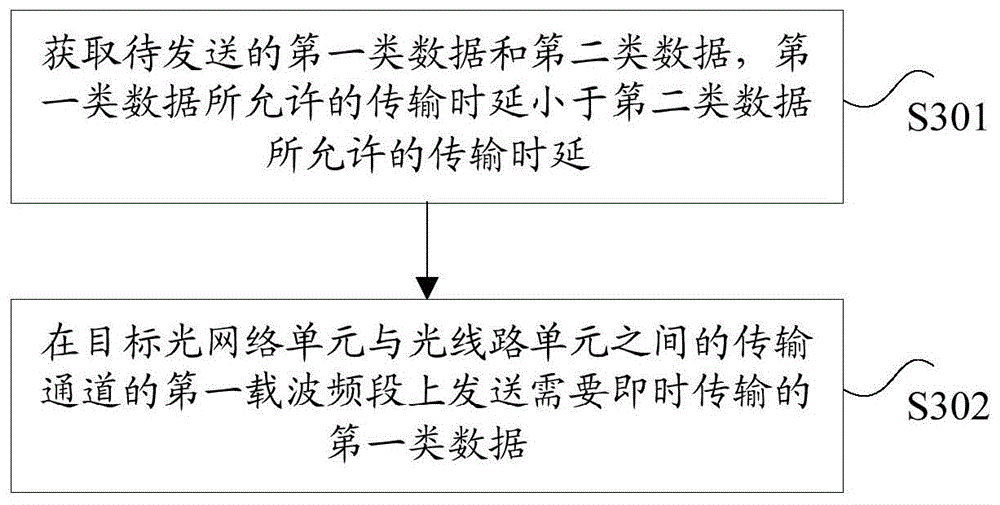
Fig. 3 is a flowchart of a data transmission method according to an embodiment of the present invention, and as shown in fig. 3, the method includes the following steps:
step S301, a first type of data and a second type of data to be transmitted are obtained, where the allowed transmission delay of the first type of data is smaller than the allowed transmission delay of the second type of data.
Step S302, a first type of data to be transmitted immediately is sent on a first carrier frequency band of a transmission channel between a target optical network unit and an optical line unit, where the transmission channel allows simultaneous transmission of the first type of data and a second type of data, and a lowest frequency in the second frequency band used for sending the second type of data on the transmission channel is higher than a highest frequency in the first carrier frequency band.
By the embodiment, the first type data and the second type data to be sent are obtained, and the transmission delay allowed by the first type data is smaller than the transmission delay allowed by the second type data; the method comprises the steps that first type data needing to be transmitted in real time are sent on a first carrier frequency band of a transmission channel between a target optical network unit and an optical line unit, the transmission channel allows the first type data and second type data to be transmitted simultaneously, the lowest frequency in the second frequency band used for sending the second type data on the transmission channel is higher than the highest frequency in the first carrier frequency band, the second type data can be sent in the existing mode, the first type data is sent in the real-time sending mode, and the two types of data are allowed to be sent simultaneously, so that the technical problem that the cost for transmitting the data with different time delays in the passive optical network is high is solved, and the technical effect of reducing the data transmission cost with different time delays in the passive optical network is achieved.
Optionally, the executing body of the above steps may be an optical network unit, an optical line unit, etc., but is not limited thereto. In this embodiment, an optical network unit is taken as an example for description.
The first type of data is data of low-latency services (i.e. low-latency data); the second type of data is data of a mobile service or a broadband service (i.e., main service data).
In the PON network system provided by the present application, the system shares an original uplink/downlink wavelength channel, a transmission mechanism of a mobile service or a broadband service (i.e., a main service) is not changed, a downlink is still in a broadcast manner, an uplink uses a DBA mechanism based on TDMA, and a low-latency service does not participate in DBA bandwidth scheduling assignment of the main service, and does not change a priority of the main service.
Different services in the PON system all use the same wavelength, in order to distinguish service signals, the system divides spectrum resources, and the traditional main service belongs to a high-speed service and corresponds to a high frequency band of a transmission channel, so that a low-delay service can be transmitted by using a low frequency band of the transmission channel. The maximum frequency of the bandwidth of the low-frequency carrier frequency band is lower than the minimum frequency of the high-speed service, and the minimum frequency of the low-frequency carrier frequency band is more than 30 KHz. The method can be realized through the following three schemes:
scheme one
The scheme is suitable for transmitting low-delay data aiming at the ONU side, each ONU is allocated with an independent low-frequency carrier frequency band with equal length, and each low-frequency carrier frequency band has a central frequency. The low-delay data sent by each ONU is based on different low-frequency carriers, so that the low-delay data can be superposed on a frequency domain and do not interfere with each other on a time domain.
In the scheme of step S302, sending the first type of data to be transmitted immediately on the first carrier frequency band of the transmission channel between the target optical network unit and the optical line unit includes: determining a first sub-frequency band allocated to a target optical network unit in a first carrier frequency band; and transmitting the first type of data on the first sub-frequency band allocated to the target optical network unit.
The first type of data is transmitted on the first sub-band allocated to the target optical network unit by the following method: carrying out carrier modulation on a first type signal for transmitting first type data by utilizing a carrier corresponding to the frequency in the first sub-frequency band; and converting the first type of signals after the carrier modulation into optical signals, and sending the optical signals on a transmission channel.
Specifically, the carrier modulation of the first type of signal for transmitting the first type of data by using the carrier corresponding to the frequency in the first sub-band includes: determining a central frequency in a first sub-frequency band allocated to a target optical network unit; the first type of signal is carrier modulated with a carrier corresponding to the center frequency.
Optionally, the low-latency data after carrier modulation may be subjected to amplitude control, and then converted into an optical signal by the ONU, and when the first type of signal after carrier modulation is converted into an optical signal and the optical signal is transmitted on a transmission channel, the signal amplitude of the first type of signal after carrier modulation may be compressed according to a preset compression ratio; and converting the compressed first-class signals into optical signals sent on a transmission channel, and finally superposing the optical signals sent by each ONU and the main service optical signals on a main optical path. Thus, the amplitude of the superimposed optical signal will not exceed the upper limit value of the main service reception by the OLT.
Optionally, in the first carrier frequency band, a sub-frequency band is allocated to each optical network unit in the passive optical network where the target optical network unit is located, where bandwidths of any two sub-frequency bands are the same, and a frequency gap is provided between two adjacent sub-frequency bands. And allocating independent equal-length carrier frequency bands allocated by each ONU in equal proportion according to the length of the total bandwidth of the low frequency band, wherein the allocated number is equal to the number of the ONUs in the network system. In addition, frequency gaps with equal length need to be inserted between every two adjacent independent carrier frequency bands.
Fig. 4 is an architecture diagram of a PON network system according to an embodiment of the present invention. The PON system mainly comprises an IP RAM router, an optical line unit OLT, an ODN network (comprising a trunk optical fiber, a branch optical fiber and an optical splitter), an optical network unit ONU (comprising an ONUp, an ONUm and an ONUn, wherein p, m and n are assumed random values), an outdoor base station and a home network. The PON system can transmit three kinds of service data. In the PON system, the main service is time-sharing forwarding based on TDMA, so that the main service can allocate independent ONU to access the PON network; each ONU can transmit low-latency traffic. As shown in fig. 4, as an embodiment of the present invention, the ONUp and the ONUn will be used to transmit mobile services; ONUm will be used to transport broadband traffic. All ONUs can transmit low-delay service without occupying the time slot and section overhead of the main service signal. The low-delay service is used as a low-amplitude signal of a channel associated to be transmitted together with the main service signal, all the low-delay services do not need to be scheduled by the DBA, are mutually overlapped in time, and can be transmitted and received simultaneously.
In the PON network system provided by the invention, in uplink transmission, when one ONU is positioned in a main service sending window, other ONUs can normally emit light at the same time, but other luminous ONUs only transmit low-delay service at the moment. Because the multiple ONUs emit light simultaneously, after all optical signals are superposed, the optical power value of the main optical path can be increased and exceeds the receiving upper limit value of the OLT receiver, so that the OLT receiver is saturated. In order to prevent other light-emitting ONUs from affecting transmission of the main service, the PON system in this patent performs amplitude attenuation control on all transmitted low-delay signals, and then superimposes these signals with the main service signal, so as to ensure that the amplitude of the superimposed signal does not exceed the upper limit of the OLT on receiving the main service.
In the downlink transmission, the main service and all the low latency services will be transmitted by the OLT at the same time. In the sending process, in order to prevent the saturation of the receiving end of the downstream ONU caused by the overlarge superimposed electrical signal, amplitude attenuation control needs to be performed on all the sent low-delay signals. And ensuring that the amplitude of the superposed signal does not exceed the receiving upper limit value of the ONU to the main service.
Fig. 5 is a schematic diagram of an alternative frequency domain based superposition according to an embodiment of the present invention. In the invention, when the low-delay data service is transmitted between the ONU and the OLT, a frequency domain superposition mechanism is adopted for uplink and downlink. In uplink and downlink transmission, low-delay data of different ONUs are modulated to different carrier frequencies, and each ONU allocates different carrier frequencies, for example, the ONUp corresponds to a carrier frequency fp, the ONUn corresponds to a carrier frequency fn, and the ONUm corresponds to a carrier frequency fm. At the transmitting end of the OLT/ONU, the low-delay data modulated by each carrier needs to control the amplitude of the signal, so as to ensure that all low-delay data after superposition does not affect the signal reception of the mobile service or the broadband service, for example, the amplitude of all optical/electrical signals after superposition may be limited to be controlled between 5% and 20% of the average amplitude of the optical/electrical signals of the main service. At the receiving end of OLT/ONU, the frequency selection is carried out on the received carrier frequency, so that the low-delay signals with carriers of different ONUs can be distinguished. Since the data transmitted by the frequency domain superposition mechanism are superposed with each other in time, all the low-latency data can be transmitted at the same time. In addition, the transmission delay of the method is not influenced by system service scheduling, and only the transmission delay of physical hardware is needed, so the delay is very low.
As shown in fig. 6, a time domain diagram of PON transmission based on frequency domain superposition is shown. The mobile service transmitted by ONUp and ONUn and the broadband service transmitted by ONUm are separated on the time domain axis, and the low-delay data transmitted by ONUP and ONUn are overlapped on the time axis. At the same time, the low-delay data transmitted by each ONU is not limited by time scheduling and can be overlapped with the main service on a time axis.
As shown in fig. 7, a frequency domain diagram of PON transmission based on frequency domain superposition is shown. The low-delay data transmitted by the ONUp and the ONUn are separated in the frequency domain, and respectively correspond to different frequencies fp and fn. Mobile services transmitted by the ONUp and the ONUn and broadband services transmitted by the ONUm are overlapped on a frequency domain.
As shown in fig. 8, the principle of PON technology based on frequency domain superposition is shown. And performing amplitude control on all the low-delay data, and superposing the low-delay data on the top end of the main service data. In an uplink channel, when the DBA authorizes one of the ONUs to open a main service window timeslot, all the ONUs can emit light, but only can transmit low-delay data, and the amplitudes of the optical signals can be controlled to a certain amplitude, so that the amplitude of the optical signal after the optical signals of all the low-delay data are superposed can be limited to be controlled to be 5% to 20% of the average amplitude of the main service optical signal. In the drawing, when the ONUp transmits the mobile service, low-delay signals with different frequencies fp and fn are superposed on the top end of the mobile service data. At an OLT/ONU receiving end, filtering a low-frequency signal through a high-pass filter, and only obtaining mobile service or broadband service; the high-frequency signal is filtered by the low-pass filter, only low-delay signals modulated by different carriers can be obtained, and carrier modulation signals with fp/fn (or fm) frequency can be respectively obtained by frequency selection through the intermediate frequency filter. And demodulating each carrier modulation signal to respectively obtain low-delay data sent by the ONUp and the ONUm.
As shown in fig. 9, the principle of the OLT transmitting front-end based on frequency domain superposition is shown. At the transmitting end of the OLT, the low-latency data transmitted downstream to each ONU is modulated by different carrier frequencies, and the modulation modes include various modulation modes such as amplitude keying, frequency shift keying, and phase shift keying. After all the modulated low-delay electrical signals are superposed, a certain amplitude attenuation is uniformly performed, for example, the amplitude of the superposed electrical signals is limited to be 5% to 20% of the average amplitude of the main service electrical signals. For example, assuming that the amplitude of the service electrical signal is 800mV, the system requires that the control amplitude is 10%, and then the sum of the amplitudes Vp-pm of all the ONU electrical signals after superposition is 800 × 10% — 80 mV. The amplitude attenuation of the signals can be realized by using an electric attenuator, and all the electric signals are superposed, converted into optical signals through a driver and electro-optical conversion and sent to the downlink main path optical fiber.
Fig. 10 shows the principle of ONU transmission front-end based on frequency domain superposition.
At the upstream ONU transmitting end, when the DBA authorizes one ONU to open the main service window time slot at the same time. All the ONUs can emit light but can only send low-delay data, each ONU carries out carrier modulation on the low-delay data by adopting allocated carrier frequency, amplitude attenuation is carried out on the modulated signals, the signals after the amplitude attenuation are converted into small current through driving, and the small current drives the photoelectric conversion unit to convert the signals into low-power optical signals. And finally, all optical signals are sent to an uplink main optical path and are multiplexed with main service light. The average power of the optical signal after the superposition of all the optical signals with low time delay data can be limited to be controlled between 5% and 20% of the average power of the main service optical signal, so that the optical power amplitude control is required to be carried out on each ONU. The average power value of the optical signal of each ONU can be allocated in equal proportion according to the number of the ONUs. For example, assuming that the average optical power of the service light is 10dBm, the control range of the system is required to be 10%, and 32 ONUs emit light in the downstream network, the sum of the average optical powers of all ONUs is required to be 10dBm to 10lg10 to 0 dBm. The average light emitting power of each ONU is 10lg (1 mW/32) ≈ 15 dBm.
Fig. 11 shows the principle of OLT/ONU reception front-end solution based on frequency domain superposition. After optical signals received by the OLT/ONU are subjected to photoelectric conversion and amplification, low-frequency and high-frequency signal separation is realized through two filters. The low-frequency signal can be filtered by a high-pass filter to obtain a mobile service or broadband service signal, the signal is a high-frequency digital signal, and the original mobile or broadband data signal can be recovered only by performing simple 0/1 level judgment. And low-delay data with carrier modulation can be obtained through a low-pass filter. The analog signal is converted into a digital signal by analog-to-digital conversion. And frequency selection is carried out through a digital band-pass filter, and low-delay digital signals with the carrier frequencies of fp and fn are separated. And demodulating the separated digital signal to remove the carrier, and finally, recovering the original low-delay data signal through 0/1 level judgment.
Through the scheme, when a certain ONU of the PON network transmits the main service signal, other ONUs of the PON network can also transmit low-delay data at the same time, and the low-delay data transmitted by each ONU is respectively modulated onto the low-frequency carrier wave of the central frequency corresponding to the ONU.
Scheme two
The scheme aims at that on the ONU side, when a certain ONU of the PON network transmits a main service signal, other multiple ONUs of the PON network can simultaneously transmit low-delay data; the low-delay data transmitted by each ONU needs to be spread by different pseudo-random sequences and then modulated onto the same low-frequency carrier. The low-delay data can be superposed on the code domain and do not interfere with each other on the time domain.
In the scheme of step S302, sending the first type of data to be transmitted immediately on the first carrier frequency band of the transmission channel between the target optical network unit and the optical line unit includes: spreading a first type signal for transmitting a first type of data; carrying out carrier modulation on the spread first-class signals by utilizing a carrier corresponding to a first frequency on a first carrier frequency band, wherein the first frequency is a frequency used when all optical network units in a passive optical network where a target optical network unit is located carry out carrier modulation; and converting the first type of signals after the carrier modulation into optical signals, and sending the optical signals on a transmission channel.
Specifically, spreading a first type of signal for transmission of a first type of data comprises: acquiring a first pseudo-random sequence distributed for a target optical network unit; spreading the first type of signals by using a first pseudorandom sequence, namely modulating all low-delay signals after spreading on the same low-frequency carrier; the low-frequency carrier frequency can be arbitrarily selected from the low-frequency band.
Optionally, the low-frequency signal after carrier modulation needs to be subjected to amplitude control, and then converted into an optical signal by the ONU, and specifically, when the first type of signal after carrier modulation is converted into an optical signal and the optical signal is sent on a transmission channel, the signal amplitude of the first type of signal after carrier modulation is compressed according to a preset compression ratio; the compressed first-class signals are converted into optical signals sent on a transmission channel, the optical signals sent by each ONU are finally superposed with main service optical signals on a main optical path, and the amplitude of the superposed optical signals does not exceed the upper limit value of the OLT for receiving the main service.
Optionally, each onu in the passive optical network is assigned a pseudorandom sequence of the same length, wherein the length of the pseudorandom sequence is related to the number of onus in the passive optical network. The length of the pseudo-random sequence code is determined by the exponent of the power of 2 corresponding to the number of ONUs.
As shown in fig. 12, the working principle of PON based on code domain superposition is shown. In the PON system of the present invention, when a low-latency data service is transmitted between the ONU and the OLT, a code domain superposition mechanism may be used for uplink and downlink. Different low-delay data are firstly coded, and then spread spectrum modulation is carried out through orthogonal sequence codes, each ONU corresponds to different orthogonal sequence codes, and different orthogonal sequence codes can identify information of different ONUs, such as the ONUp corresponding sequence code PNp and the ONUn corresponding sequence code PNn. All the low-delay data after the spread spectrum modulation are modulated by carrier waves, and the carrier frequency can select an appropriate frequency f at a low frequency band. Because the data transmitted by the code domain superposition mechanism are mutually superposed on the time domain and the code domain, the ONUp and the ONUn can transmit the low-delay data at the same time. The transmission delay of the method is not influenced by system service scheduling, and only the transmission delay of physical hardware is needed, so the delay is very low.
As shown in fig. 13, the time domain and code domain of PON transmission based on code domain superposition are shown. Mobile traffic for ONUp and ONUn transmissions and broadband traffic for ONUm transmissions are separated in the time and code domains. The low latency data transmitted by ONUP and ONUn overlap in the time and code domains. At the same time, the low-delay data transmitted by each ONU is not limited by time scheduling and can be overlapped with the main service on a time axis.
As shown in fig. 14, the frequency domain and code domain of PON transmission based on code domain superposition are shown. The low-delay data transmitted by the ONU and the main service are separated on a frequency domain, the low-delay data is in a low frequency band corresponding to a carrier frequency f, and the main service is in a high frequency band. Mobile services transmitted by the ONUp and the ONUn and broadband services transmitted by the ONUm are overlapped on a frequency domain. The low-latency data transmitted by ONUp and ONUn overlap in the code domain.
As shown in fig. 15, the principle of PON technology based on code domain superposition is shown. And carrying out amplitude control on all the low-delay data, and superposing the low-delay data on the top end of the main service data. In an uplink channel, when a DBA authorizes one of the ONUs to open a main service window timeslot, all the ONUs can emit light, but only low-delay data can be transmitted, the amplitudes of the optical signals can be controlled to a certain amplitude, and the amplitude of the optical signal after the optical signals of all the low-delay data are superposed is regulated to be controlled to be between 5% and 20% of the average amplitude of the main service optical signal. In fig. 15, when the ONUp transmits a mobile service, different sequence codes PNp and low-latency data spread by PNn are finally carrier-modulated together by a carrier f, and all data are controlled by amplitude attenuation and then superimposed on the top of the mobile service data. At a receiving end, filtering low-frequency signals through a high-pass filter to obtain mobile services; the high-frequency signals are filtered by a low-pass filter to obtain low-frequency low-delay data with carrier modulation, and then carrier frequencies are demodulated and filtered to respectively obtain the low-delay data superposed after frequency spreading. And despreading the superposed data by adopting different sequence codes to obtain low-delay data of different ONUs.
As shown in fig. 16, the principle of OLT transmission front-end solution of code domain superposition is shown. At the transmitting end of the OLT, the ONUp/ONUm low-delay data is firstly coded, and then spread by a sequence code PNp/PNm. The spread data is subjected to carrier modulation through the same carrier frequency f and is superposed on the mobile service or broadband service electric signal after amplitude attenuation. The principle of all ONU amplitude control is the same as that of the FDAM OLT transmitting end. All the electric signals are superposed and converted into optical signals through a driver and electro-optical conversion, and the optical signals are sent to the downlink main path optical fiber.
As shown in fig. 17, the principle of ONU transmission front-end based on code domain superposition is shown. In an uplink channel, low-delay data sent by each ONUp/ONUm/ONUn is firstly coded and then spread by a sequence code PNp/PNm/PNn. The spread data is subjected to carrier modulation by the same carrier frequency f, and then the modulated electric signal is subjected to amplitude attenuation, driving and photoelectric conversion into an optical signal. All the low-delay optical signals uploaded by the ONU are multiplexed with the optical signals of the mobile service or the broadband service on the main optical path. The principle of all ONU low-delay optical power control is the same as that of the FDAM ONU transmitting end.
As shown in fig. 18, the principle of OLT/ONU reception front-end solution based on code domain superposition is shown. After the received optical signals are subjected to photoelectric conversion and amplification, low-frequency and high-frequency signal separation is realized through two filters. The low-frequency signals can be filtered by a high-pass filter to obtain mobile service or broadband service signals, and the original mobile or broadband data signals can be recovered only by carrying out simple 0/1 level judgment. Low-delay data with carrier modulation can be obtained through a low-pass filter. The low-delay data of different ONU can be obtained by carrying out analog-to-digital conversion to digital signals, carrying out carrier demodulation and spread spectrum on the digital signals, then superposing the low-delay data, despreading the low-delay data by adopting corresponding sequence codes and then decoding the low-delay data.
The scheme uses a code domain superposition technology, does not need to allocate frequency bandwidth, and has small transmission rate constrained by the bandwidth. However, the longer sequence code is needed to spread the effective data, the more the number of ONUs is, the longer the bit of the required sequence code is, the longer the code after spreading is, and the less the effective data amount is transmitted in the same time.
Scheme three
And carrying out grouping classification on the ONUs in the PON network system, dividing the total quantity into M multiplied by N combinations according to the number of the ONUs, wherein M groups exist in total, and each group has N ONUs. M different groups respectively use M different and independent low-frequency carrier frequency bands; equal-length frequency gaps need to be inserted between every two adjacent independent carrier frequency bands, and N ONUs in the same group use the same low-frequency carrier frequency band; each low-frequency carrier frequency band corresponds to a central frequency, each carrier frequency band is subjected to M equal proportion distribution according to the length of the total bandwidth of the low-frequency band, and N ONUs in the same group need to use N different pseudorandom sequences for spreading.
In the scheme of step S302, when the first type of data to be transmitted immediately is sent on the first carrier frequency band of the transmission channel between the target optical network unit and the optical line unit, the low-latency data transmitted by each ONU needs to be spread by different pseudo-random sequences in the corresponding group, and then carrier modulation is performed by using the low-frequency carrier frequency of the corresponding group, which may specifically be implemented as follows: spreading a first type of signal for transmission of a first type of data; carrying out carrier modulation on the spread first-class signals by utilizing a carrier corresponding to a second frequency on the first carrier frequency band, wherein the second frequency is a frequency used when all optical network units in an optical network unit group where the target optical network unit is located carry out carrier modulation; and converting the first type of signals after the carrier modulation into optical signals, and sending the optical signals on a transmission channel.
Before performing spectrum spreading on a first type of signal used for transmitting first type of data, an optical network unit group where a target optical network unit is located may be determined, where a passive optical network where the target optical network unit is located includes a plurality of optical network unit groups, and each optical network unit group includes a plurality of optical network units.
In this way, spreading the first type of signals for transmitting the first type of data includes acquiring a plurality of pseudo-random sequences allocated to an optical network unit group in which the target optical network unit is located; acquiring a second pseudo-random sequence corresponding to the target optical network unit in the plurality of pseudo-random sequences; the first type of signal is spread with a second pseudo-random sequence.
The length of the above-mentioned pseudo-random sequence is related to the number of optical network elements in the optical network element group. The length of the pseudo-random sequence code is determined by an exponent of 2 corresponding to N.
Optionally, the carrier modulating the spread first type of signal with a carrier corresponding to a second frequency on the first carrier band includes: acquiring a second sub-frequency band allocated to an optical network unit group where a target optical network unit is located on the first carrier frequency band; and carrying out carrier modulation on the spread first-class signals by utilizing a carrier corresponding to a second frequency on the second sub-frequency band.
The second frequency may be a center frequency in the second sub-band.
Optionally, all the low-delay signals after spreading may be modulated onto the low-frequency carrier of the corresponding group, and when the first type of signal after carrier modulation is converted into an optical signal and the optical signal is sent on the transmission channel, the low-frequency signal after carrier modulation needs to be amplitude-controlled and then converted into an optical signal by the ONU, which is specifically as follows: compressing the signal amplitude of the first type of signals after carrier modulation according to a preset compression ratio; the compressed first-class signals are converted into optical signals sent on a transmission channel, the optical signals sent by each ONU are finally superposed with main service optical signals on a main optical path, and the amplitude of the superposed optical signals does not exceed the upper limit value of the OLT for receiving the main service.
In the above embodiment, on the ONU side, while a certain ONU in the PON network transmits the main service signal, other ONUs in the PON network can also transmit low-latency data at the same time.
As shown in fig. 19, the working principle of PON based on frequency domain superposition and code domain superposition is shown. In the PON system of the present invention, the low-latency data transmission in the uplink/downlink channel may also adopt a combination of frequency domain superposition and code domain superposition. As in fig. 19, assuming that ONUs are divided into groups each consisting of 16 ONUs (the combination may be arbitrarily selected), ONUm1-ONUm16, ONUp1-ONUp16, ONUn1-ONUn 16. The three different groups of ONUs use frequencies fm1, fp1, fn1 as carrier frequencies, respectively. The 16 ONUs in the same group are spread with 16 different sequence codes PN1-PN 16. Different groups of ONUs may reuse the 16 sequence codes. Different ONUs can be distinguished by a combination of carrier frequency and sequence code. As with the code domain superposition principle, it is first necessary to encode low-delay data of different ONUs, then perform spread spectrum modulation by using sequence codes, and finally perform carrier modulation by using corresponding carrier frequencies. For example, ONUm1 is spread with a PN1 sequence code and carrier modulated with fm 1. ONUm16 is spread with PN16 sequence code and carrier modulated with fm 1. Because the data transmitted by combining the frequency domain superposition and the code domain superposition mechanisms can also be superposed on the time domain and the code domain, different ONUs can transmit low-delay data at the same time. The transmission delay of the method is not influenced by system service scheduling, and only the transmission delay of physical hardware is needed, so the delay is very low.
As shown in fig. 20, the PON transmission frequency domain and code domain based on frequency domain superposition and code domain superposition are shown. The low-delay data and the main service transmitted by the ONU are respectively in a low-frequency band and a high-frequency band on a frequency domain. The ONU low-delay data of the same group correspond to the same frequency, and the different ONU low-delay data in the same group are superposed on a code domain. Different groups of ONUs correspond to different frequencies. For example: the ONUm1 and ONUm16 low latency data are both at frequency fm1 in the frequency domain, and ONUn1 and ONUn16 correspond to carrier frequency fn 1. The ONUm1/ONUn1 and ONUm16/ONUn16 low latency data are overlapped in the code domain.
As shown in fig. 21, the principle of PON technology based on frequency domain superposition and code domain superposition is shown. And carrying out amplitude control on all the low-delay data, and superposing the low-delay data on the top end of the main service data. On the uplink channel, when the DBA authorizes one of the ONUs to open the time slot of the main service window, all ONUs can emit light but only can transmit low-delay data, the amplitudes of the optical signals can be controlled to a certain amplitude, and the amplitude of the optical signal after the optical signals of all the low-delay data are superposed is regulated to be controlled to be between 5% and 20% of the average amplitude of the main service optical signal. In fig. 21, when the OLT sends a mobile service, different sequence codes PN1-PN16 spread different low-delay data in the same group, the ONUp1-ONUp16 perform carrier modulation by using a carrier fp1, the ONUn1-ONUn16 perform carrier modulation by using a carrier fn1, and all data are superimposed on the top of the mobile service data after amplitude attenuation control. At a receiving end, a low-frequency signal is filtered by a high-pass filter, so that mobile service can be obtained; the high-frequency signals are filtered by the low-pass filter, low-frequency low-delay data with carrier modulation are obtained, and different carrier frequencies can be selected by the intermediate-frequency filters with different central frequencies. For example, the frequency selected by the intermediate frequency filter is fp1, and only the fp1 carrier signal is reserved after the low-delay signal passes through the filter. The signal is demodulated to remove the carrier wave, and the low-delay data superposed on the frequency point can be obtained. And then, the data signal is despread by adopting a corresponding sequence code, and the data which cannot be despread is discarded, so that the low-delay data corresponding to the ONUp1 can be obtained finally.
As shown in fig. 22, the principle of the OLT transmission front-end based on frequency domain superposition and code domain superposition is shown. At the transmitting end of the OLT, the ONUp1/ONUm1 low-latency data is firstly coded and then spread by a sequence code PN 1. The spread data will be carrier modulated by different carrier frequencies fp1 and fm1 and superimposed on the mobile service or broadband service electrical signal after amplitude attenuation. The principle of amplitude control of all ONU low-delay electric signals is the same as that of the transmitting end of the FDAM/code domain superposition OLT. All the electric signals are superposed and converted into optical signals through a driver and electro-optical conversion, and the optical signals are sent to the downlink main path optical fiber.
As shown in fig. 23, the principle of the ONU transmission front end based on frequency domain superposition and code domain superposition is shown. In the uplink channel, each ONUp1/ONUp16/ONUm1/ONUm16 encodes the transmitted low-latency data first, and then spreads the data by the sequence codes PN1/PN 16. The spread data are respectively subjected to carrier modulation through different carrier frequencies fp1 and fm1, and then the modulated electric signals are subjected to amplitude attenuation and are subjected to driving and photoelectric conversion to be optical signals. All the low-delay optical signals uploaded by the ONU are multiplexed with the optical signals of the mobile service or the broadband service on the main optical path. The principle of all ONU low-delay optical power control is the same as that of the FDAM ONU transmitting end.
As shown in fig. 24, the principle of OLT/ONU reception front-end solution based on frequency domain superposition and code domain superposition is shown. After the received optical signals are subjected to photoelectric conversion and amplification, low-frequency and high-frequency signal separation is realized through two filters. The low-frequency signals can be filtered by a high-pass filter to obtain mobile service or broadband service signals, and the original mobile or broadband data signals can be recovered only by carrying out simple 0/1 level judgment. Low-delay data with a carrier can be obtained through a low-pass filter. The digital signals are converted into digital signals through analog-digital conversion, and the carrier frequency selection is carried out on the digital signals through different band-pass filters. For example: the modulated signals with carrier frequencies fp1 and fm1 can be selected by bandpass filters. The two paths of signals are respectively demodulated and then carrier waves are removed, and low-delay data superposed on each frequency point can be obtained. For example, the intermediate frequency filter selects fp1 as the frequency, and the low latency signal only retains the fp1 carrier signal after passing through the filter. The signal is demodulated to remove the carrier wave, and the low-delay data superposed on the frequency point can be obtained. And then, despreading the data signal by adopting a corresponding sequence code, discarding data which cannot be despread, and finally obtaining low-delay data corresponding to the ONUp 1.
The scheme combines two technologies of frequency domain superposition and code domain superposition, and can be realized by only allocating less low-frequency bands and shorter sequence codes in a combined mode of the two technologies, so that the transmission rate of the ONU is not influenced by the number of the ONU.
In the embodiment of the application, the original upper and lower wavelengths are adopted in the PON system, and the low-latency service and the main service are isolated by the high and low frequency spectrums, and in addition, all low-latency data are transmitted simultaneously in the PON network topology structure based on a method of superimposing multiple signals in a frequency domain or a code domain, so that the transmission latency of the data can be greatly reduced. The system is realized by only adding a set of transmitting and receiving electric devices in the original system without changing optical path devices, and the cost is increased very little. The PON system provided by the patent has the advantages of low cost, high bandwidth utilization rate, flexible service transmission and capability of transmitting ultra-low delay service.
In the embodiment of the present application, the execution subject of step S302 to step S304 may be an optical line unit or the like, and the optical line unit is taken as an example in the present embodiment for description.
Fig. 25 is a flowchart of a data transmission method according to an embodiment of the present invention, as shown in fig. 25, the method includes the steps of:
step S2501, receiving a first type of data and a second type of data requested to be sent to a target optical network unit on an optical line unit, wherein the allowed transmission delay of the first type of data is smaller than the allowed transmission delay of the second type of data;
step S2502, sending a first type of data to be transmitted instantly on a first carrier frequency band of a transmission channel between the transmission channel and a target optical network unit, where the transmission channel allows simultaneous transmission of the first type of data and a second type of data, and a lowest frequency in the second frequency band used for sending the second type of data on the transmission channel is higher than a highest frequency in the first carrier frequency band.
Through the steps, the second type of data can be sent according to the existing mode, the first type of data is sent in an instant sending mode, and the two types of data are allowed to be sent simultaneously, so that the technical problem that the cost for transmitting the data with different time delays in the passive optical network is high is solved, and the technical effect of reducing the data transmission cost with different time delays in the passive optical network is achieved.
The first type of data is data of low-latency services (i.e. low-latency data); the second type of data is data of a mobile service or a broadband service (i.e., main service data).
In the PON network system provided by the present application, the system shares an original uplink/downlink wavelength channel, a transmission mechanism of a mobile service or a broadband service (i.e., a main service) is not changed, a downlink is still in a broadcast manner, an uplink uses a DBA mechanism based on TDMA, and a low-latency service does not participate in DBA bandwidth scheduling assignment of the main service, and does not change a priority of the main service.
Different services in the PON system all use the same wavelength, in order to distinguish service signals, the system divides spectrum resources, and the traditional main service belongs to a high-speed service and corresponds to a high frequency band of a transmission channel, so that a low-delay service can be transmitted by using a low frequency band of the transmission channel. The maximum frequency of the bandwidth of the low-frequency carrier frequency band is lower than the minimum frequency of the high-speed service, and the minimum frequency of the low-frequency carrier frequency band is more than 30 KHz. The method can be realized through the following three schemes:
scheme one
In the technical solution of step S2502, the sending of the first type of data that needs to be instantly transmitted on the first carrier frequency band of the transmission channel with the target optical network unit includes: determining a first sub-frequency band allocated to a target optical network unit in a first carrier frequency band; and transmitting the first type of data on the first sub-frequency band allocated to the target optical network unit.
Optionally, the sending the first type of data on the first sub-band allocated to the target optical network unit includes: carrying out carrier modulation on a first type of signal for transmitting first type of data by utilizing a carrier corresponding to the frequency in the first sub-frequency band; and converting the first type of signals after the carrier modulation into optical signals, and sending the optical signals on a transmission channel.
Optionally, the carrier modulating, by using a carrier corresponding to a frequency in the first sub-band, a first type of signal for transmitting a first type of data includes: determining a central frequency in a first sub-frequency band allocated to a target optical network unit; the first type of signal is carrier modulated with a carrier corresponding to the center frequency.
Optionally, the first type of signal after carrier modulation is converted into an optical signal, and when the optical signal is sent on a transmission channel, the signal amplitude of the first type of signal after carrier modulation can be compressed according to a preset compression ratio; the compressed first type signal is converted into an optical signal transmitted over a transmission channel.
Optionally, in the first carrier frequency band, a sub-frequency band is allocated to each optical network unit in the passive optical network where the target optical network unit is located, where bandwidths of any two sub-frequency bands are the same, and a frequency gap is provided between two adjacent sub-frequency bands.
In the above embodiment, the OLT of the PON network modulates the low-delay data transmitted to the plurality of ONUs onto the low-frequency carriers of the corresponding center frequencies, respectively; all low-delay data signals subjected to carrier modulation need to be subjected to amplitude control and are superposed with the main service electric signals; the amplitude of the superimposed electrical signal cannot exceed the upper limit value of the main service reception by the ONU. Thus, instant transmission of low-latency data is realized.
Scheme two
In the technical solution of step S2502, sending the first type of data to be instantly transmitted on the first carrier frequency band of the transmission channel with the target optical network unit includes: spreading a first type of signal for transmission of a first type of data; carrying out carrier modulation on the spread first-class signals by utilizing a carrier corresponding to a first frequency on a first carrier frequency band, wherein the first frequency is a frequency used when all optical network units in a passive optical network where a target optical network unit is located carry out carrier modulation; and converting the first type of signals after the carrier modulation into optical signals, and sending the optical signals on a transmission channel.
Optionally, spreading the first type of signal for transmitting the first type of data comprises: acquiring a first pseudo-random sequence distributed for a target optical network unit; a first type of signal is spread with a first pseudo-random sequence.
Optionally, when the first type of signal after carrier modulation is converted into an optical signal and the optical signal is sent on a transmission channel, the signal amplitude of the first type of signal after carrier modulation may be compressed according to a preset compression ratio; the compressed first type signal is converted into an optical signal transmitted over a transmission channel.
Optionally, each onu in the passive optical network is assigned a pseudorandom sequence of the same length, wherein the length of the pseudorandom sequence is related to the number of onus in the passive optical network.
In this embodiment, an OLT of a PON network performs spread spectrum modulation on low-delay data transmitted to a plurality of ONUs by using corresponding pseudorandom sequence codes, respectively; the length of the pseudo-random sequence code is determined by the exponent of the power of 2 corresponding to the number of the ONUs. Then modulating all the low-delay signals after the spread spectrum on the same low-frequency carrier; the low-frequency carrier frequency can be randomly selected in a low-frequency band, and all low-delay electrical signals and main service electrical signals are superposed; the amplitude of the superimposed electric signal cannot exceed the upper limit value of the main service reception by the ONU.
Scheme three
In the technical solution of step S2502, sending the first type of data to be instantly transmitted on the first carrier frequency band of the transmission channel with the target optical network unit includes: spreading a first type of signal for transmission of a first type of data; carrying out carrier modulation on the spread first-class signals by utilizing a carrier corresponding to a second frequency on the first carrier frequency band, wherein the second frequency is a frequency used when all optical network units in an optical network unit group where the target optical network unit is located carry out carrier modulation; and converting the first type of signals after the carrier modulation into optical signals, and sending the optical signals on a transmission channel.
Optionally, before performing spectrum spreading on a first type of signal used for transmitting first type of data, an optical network unit group where a target optical network unit is located is determined, where a passive optical network where the target optical network unit is located includes a plurality of optical network unit groups, and each optical network unit group includes a plurality of optical network units.
Optionally, spreading the first type of signal for transmitting the first type of data comprises: acquiring a plurality of pseudo-random sequences distributed for an optical network unit group where a target optical network unit is located; acquiring a second pseudo-random sequence corresponding to the target optical network unit in the plurality of pseudo-random sequences; the first type of signal is spread with a second pseudo-random sequence.
Optionally, the length of the pseudo-random sequence is related to the number of optical network elements within the group of optical network elements.
Optionally, the carrier modulating the spread first type of signal with a carrier corresponding to a second frequency on the first carrier band includes: acquiring a second sub-frequency band allocated to an optical network unit group where a target optical network unit is located on the first carrier frequency band; and carrying out carrier modulation on the spread first-class signals by utilizing a carrier corresponding to a second frequency on the second sub-frequency band.
Optionally, the second frequency is a center frequency within the second sub-band.
Optionally, when the first type of signal after carrier modulation is converted into an optical signal and the optical signal is sent on a transmission channel, compressing the signal amplitude of the first type of signal after carrier modulation according to a preset compression ratio; the compressed first type of signal is converted into an optical signal that is transmitted over a transmission channel.
In this embodiment, an OLT of the PON network performs spread spectrum modulation on low-delay data transmitted to multiple ONUs by using pseudorandom sequence codes in corresponding groups, respectively; the length of the pseudo-random sequence code is determined by the exponent of the power of 2 corresponding to N. Then modulating all low-delay signals after the spread spectrum on low-frequency carriers of the corresponding group of the ONU; superposing all the low-delay electrical signals with the main service electrical signals; the amplitude of the superimposed electrical signal cannot exceed the upper limit value of the main service reception by the ONU.
It should be noted that the three schemes of the OLT side method correspond to the three schemes of the ONU side, and are not described herein again.
Through the above description of the embodiments, those skilled in the art can clearly understand that the method according to the above embodiments can be implemented by software plus a necessary general hardware platform, and certainly can also be implemented by hardware, but the former is a better implementation mode in many cases. Based on such understanding, the technical solutions of the present invention may be embodied in the form of a software product, which is stored in a storage medium (e.g., ROM/RAM, magnetic disk, optical disk) and includes instructions for enabling a terminal device (e.g., a mobile phone, a computer, a server, or a network device) to execute the method according to the embodiments of the present invention.
Example 2
The embodiment of the invention also provides a data transmission device. The device is used for implementing the above embodiments and preferred embodiments, and the description of the device is omitted. As used below, the term "module" may be a combination of software and/or hardware that implements a predetermined function. Although the means described in the embodiments below are preferably implemented in software, an implementation in hardware, or a combination of software and hardware is also possible and contemplated.
Fig. 26 is a schematic diagram of a data transmission apparatus according to an embodiment of the present invention. As shown in fig. 26, the apparatus may include: a receiving unit 261 and a transmitting unit 262.
A receiving unit 261, configured to obtain first type data and second type data to be sent, where a transmission delay allowed for the first type data is smaller than a transmission delay allowed for the second type data;
a transmission unit 262, configured to send first type data that needs to be transmitted immediately on a first carrier frequency band of a transmission channel between the target optical network unit and the optical line unit, where the transmission channel allows simultaneous transmission of the first type data and second type data, and a lowest frequency in the second frequency band used for sending the second type data on the transmission channel is higher than a highest frequency in the first carrier frequency band.
By the embodiment, the receiving unit acquires the first type of data and the second type of data to be transmitted, wherein the transmission delay allowed by the first type of data is less than the transmission delay allowed by the second type of data; the transmission unit sends first type data needing immediate transmission on a first carrier frequency band of a transmission channel between a target optical network unit and an optical line unit, wherein the transmission channel allows the first type data and second type data to be transmitted simultaneously, and the lowest frequency in the second frequency band used for sending the second type data on the transmission channel is higher than the highest frequency in the first carrier frequency band. The second type of data can be sent according to the existing mode, the first type of data is sent in an instant sending mode, and the two types of data are allowed to be sent simultaneously, so that the technical problem that the cost for transmitting the data with different time delays in the passive optical network is high is solved, and the technical effect of reducing the data transmission cost with different time delays in the passive optical network is achieved.
In the above embodiment, the transmission unit includes: the determining module is used for determining a first sub-frequency band allocated to the target optical network unit in the first carrier frequency band; and the transmission module is used for transmitting the first type of data on the first sub-frequency band allocated to the target optical network unit.
Optionally, the transmission module comprises: the modulation submodule is used for carrying out carrier modulation on a first type signal for transmitting first type data by utilizing a carrier corresponding to the frequency in the first sub-frequency band; and the transmission submodule is used for converting the first type of signals after the carrier modulation into optical signals and sending the optical signals on a transmission channel.
Optionally, the transmission sub-module is further configured to, before converting the first type of signal after the carrier modulation into an optical signal and sending the optical signal on a transmission channel, compress the signal amplitude of the first type of signal after the carrier modulation according to a preset compression ratio, and then convert the first type of signal after the compression into the optical signal sent on the transmission channel.
Optionally, in the first carrier frequency band, a sub-frequency band is allocated to each optical network unit in the passive optical network where the target optical network unit is located, where bandwidths of any two sub-frequency bands are the same, and a frequency gap is provided between two adjacent sub-frequency bands.
Optionally, the transmission unit includes: the first spread spectrum module is used for spreading a first type of signals for transmitting first type of data; the first modulation module is used for carrying out carrier modulation on the spread first-class signals by utilizing a carrier corresponding to a first frequency on a first carrier frequency band, wherein the first frequency is a frequency used when all optical network units in a passive optical network where the target optical network unit is located carry out carrier modulation; the first conversion module is used for converting the first type of signals after the carrier modulation into optical signals and sending the optical signals on a transmission channel.
Optionally, the first spreading module is further configured to obtain a first pseudorandom sequence allocated to the target optical network unit; the first type of signal is spread with a first pseudo-random sequence. The first type of signal after carrier modulation is converted into an optical signal, before the optical signal is sent on a transmission channel, the signal amplitude of the first type of signal after carrier modulation can be compressed according to a preset compression ratio, and then the first type of signal after compression is converted into the optical signal sent on the transmission channel.
Optionally, each onu in the passive optical network is assigned a pseudorandom sequence with the same length, where the length of the pseudorandom sequence is related to the number of onu in the passive optical network.
Optionally, the transmission unit includes: the second spread spectrum module is used for spreading the first type of signals used for transmitting the first type of data; the second modulation module is used for carrying out carrier modulation on the spread first-class signals by utilizing a carrier corresponding to a second frequency on the first carrier frequency band, wherein the second frequency is a frequency used when all optical network units in an optical network unit group where the target optical network unit is located carry out carrier modulation; and the second conversion module is used for converting the first type of signals after the carrier modulation into optical signals and sending the optical signals on a transmission channel.
Optionally, the second spreading module is further configured to determine an optical network unit group in which the target optical network unit is located before spreading the first type of signals for transmitting the first type of data, where the passive optical network in which the target optical network unit is located includes a plurality of optical network unit groups, and each optical network unit group includes a plurality of optical network units.
Optionally, when the second spectrum spreading module spreads the spectrum of the first type of signal used for transmitting the first type of data, a plurality of pseudo-random sequences allocated to the optical network unit group in which the target optical network unit is located are obtained first; acquiring a second pseudo-random sequence corresponding to the target optical network unit in the plurality of pseudo-random sequences; the first type of signal is spread with a second pseudo-random sequence.
The length of the above-mentioned pseudo-random sequence is related to the number of optical network elements in the optical network element group.
The second modulation module is further configured to acquire a second sub-band allocated to the optical network unit group in which the target optical network unit is located on the first carrier band; and carrying out carrier modulation on the spread first-class signals by utilizing a carrier corresponding to a second frequency on the second sub-frequency band. The second frequency is a center frequency within the second sub-band.
The second conversion module is used for converting the first type of signals after the carrier modulation into optical signals and compressing the signal amplitude of the first type of signals after the carrier modulation according to a preset compression ratio before the optical signals are sent on a transmission channel; the compressed first type of signal is then converted into an optical signal that is transmitted over a transmission channel.
It should be noted that, the above modules may be implemented by software or hardware, and for the latter, the following may be implemented, but not limited to: the modules are all positioned in the same processor; alternatively, the modules are respectively located in different processors in any combination.
Example 3
The embodiment of the invention also provides a storage medium. Alternatively, in the present embodiment, the storage medium may be configured to store program codes for performing the following steps:
s11, acquiring first-class data and second-class data to be transmitted, wherein the transmission delay allowed by the first-class data is less than the transmission delay allowed by the second-class data;
s12, sending a first type of data to be transmitted immediately on a first carrier frequency band of a transmission channel between the target optical network unit and the optical line unit, where the transmission channel allows simultaneous transmission of the first type of data and a second type of data, and a lowest frequency in the second frequency band used for sending the second type of data on the transmission channel is higher than a highest frequency in the first carrier frequency band.
Optionally, in this embodiment, the storage medium may include, but is not limited to: a U-disk, a Read-Only Memory (ROM), a Random Access Memory (RAM), a removable hard disk, a magnetic disk, or an optical disk, and various media capable of storing program codes.
Optionally, in this embodiment, the processor executes, according to the program code stored in the storage medium: acquiring first-class data and second-class data to be transmitted, wherein the transmission delay allowed by the first-class data is smaller than the transmission delay allowed by the second-class data; the method comprises the steps of sending first-class data needing to be transmitted instantly on a first carrier frequency band of a transmission channel between a target optical network unit and an optical line unit, wherein the transmission channel allows the first-class data and second-class data to be transmitted simultaneously, and the lowest frequency in a second frequency band used for sending the second-class data on the transmission channel is higher than the highest frequency in the first carrier frequency band.
Optionally, the specific examples in this embodiment may refer to the examples described in the above embodiments and optional implementation manners, and this embodiment is not described herein again.
It will be apparent to those skilled in the art that the modules or steps of the present invention described above may be implemented by a general purpose computing device, they may be centralized on a single computing device or distributed across a network of multiple computing devices, and alternatively, they may be implemented by program code executable by a computing device, such that they may be stored in a storage device and executed by a computing device, and in some cases, the steps shown or described may be performed in an order different than that described herein, or they may be separately fabricated into individual integrated circuit modules, or multiple ones of them may be fabricated into a single integrated circuit module. Thus, the present invention is not limited to any specific combination of hardware and software.
The above description is only a preferred embodiment of the present invention and is not intended to limit the present invention, and various modifications and changes may be made by those skilled in the art. Any modification, equivalent replacement, or improvement made within the spirit and principle of the present invention should be included in the protection scope of the present invention.