CN108370619B - Micro-wave oven - Google Patents
Micro-wave oven Download PDFInfo
- Publication number
- CN108370619B CN108370619B CN201780004503.8A CN201780004503A CN108370619B CN 108370619 B CN108370619 B CN 108370619B CN 201780004503 A CN201780004503 A CN 201780004503A CN 108370619 B CN108370619 B CN 108370619B
- Authority
- CN
- China
- Prior art keywords
- cooking chamber
- food
- tray
- reflection part
- microwave oven
- Prior art date
- Legal status (The legal status is an assumption and is not a legal conclusion. Google has not performed a legal analysis and makes no representation as to the accuracy of the status listed.)
- Expired - Fee Related
Links
Images




Classifications
-
- H—ELECTRICITY
- H05—ELECTRIC TECHNIQUES NOT OTHERWISE PROVIDED FOR
- H05B—ELECTRIC HEATING; ELECTRIC LIGHT SOURCES NOT OTHERWISE PROVIDED FOR; CIRCUIT ARRANGEMENTS FOR ELECTRIC LIGHT SOURCES, IN GENERAL
- H05B6/00—Heating by electric, magnetic or electromagnetic fields
- H05B6/64—Heating using microwaves
- H05B6/72—Radiators or antennas
- H05B6/725—Rotatable antennas
-
- H—ELECTRICITY
- H05—ELECTRIC TECHNIQUES NOT OTHERWISE PROVIDED FOR
- H05B—ELECTRIC HEATING; ELECTRIC LIGHT SOURCES NOT OTHERWISE PROVIDED FOR; CIRCUIT ARRANGEMENTS FOR ELECTRIC LIGHT SOURCES, IN GENERAL
- H05B6/00—Heating by electric, magnetic or electromagnetic fields
- H05B6/64—Heating using microwaves
- H05B6/6408—Supports or covers specially adapted for use in microwave heating apparatus
-
- H—ELECTRICITY
- H05—ELECTRIC TECHNIQUES NOT OTHERWISE PROVIDED FOR
- H05B—ELECTRIC HEATING; ELECTRIC LIGHT SOURCES NOT OTHERWISE PROVIDED FOR; CIRCUIT ARRANGEMENTS FOR ELECTRIC LIGHT SOURCES, IN GENERAL
- H05B6/00—Heating by electric, magnetic or electromagnetic fields
- H05B6/64—Heating using microwaves
- H05B6/6408—Supports or covers specially adapted for use in microwave heating apparatus
- H05B6/6411—Supports or covers specially adapted for use in microwave heating apparatus the supports being rotated
-
- H—ELECTRICITY
- H05—ELECTRIC TECHNIQUES NOT OTHERWISE PROVIDED FOR
- H05B—ELECTRIC HEATING; ELECTRIC LIGHT SOURCES NOT OTHERWISE PROVIDED FOR; CIRCUIT ARRANGEMENTS FOR ELECTRIC LIGHT SOURCES, IN GENERAL
- H05B6/00—Heating by electric, magnetic or electromagnetic fields
- H05B6/64—Heating using microwaves
- H05B6/6402—Aspects relating to the microwave cavity
-
- H—ELECTRICITY
- H05—ELECTRIC TECHNIQUES NOT OTHERWISE PROVIDED FOR
- H05B—ELECTRIC HEATING; ELECTRIC LIGHT SOURCES NOT OTHERWISE PROVIDED FOR; CIRCUIT ARRANGEMENTS FOR ELECTRIC LIGHT SOURCES, IN GENERAL
- H05B6/00—Heating by electric, magnetic or electromagnetic fields
- H05B6/64—Heating using microwaves
- H05B6/6447—Method of operation or details of the microwave heating apparatus related to the use of detectors or sensors
-
- H—ELECTRICITY
- H05—ELECTRIC TECHNIQUES NOT OTHERWISE PROVIDED FOR
- H05B—ELECTRIC HEATING; ELECTRIC LIGHT SOURCES NOT OTHERWISE PROVIDED FOR; CIRCUIT ARRANGEMENTS FOR ELECTRIC LIGHT SOURCES, IN GENERAL
- H05B6/00—Heating by electric, magnetic or electromagnetic fields
- H05B6/64—Heating using microwaves
- H05B6/72—Radiators or antennas
-
- H—ELECTRICITY
- H05—ELECTRIC TECHNIQUES NOT OTHERWISE PROVIDED FOR
- H05B—ELECTRIC HEATING; ELECTRIC LIGHT SOURCES NOT OTHERWISE PROVIDED FOR; CIRCUIT ARRANGEMENTS FOR ELECTRIC LIGHT SOURCES, IN GENERAL
- H05B6/00—Heating by electric, magnetic or electromagnetic fields
- H05B6/64—Heating using microwaves
- H05B6/74—Mode transformers or mode stirrers
-
- H—ELECTRICITY
- H05—ELECTRIC TECHNIQUES NOT OTHERWISE PROVIDED FOR
- H05B—ELECTRIC HEATING; ELECTRIC LIGHT SOURCES NOT OTHERWISE PROVIDED FOR; CIRCUIT ARRANGEMENTS FOR ELECTRIC LIGHT SOURCES, IN GENERAL
- H05B6/00—Heating by electric, magnetic or electromagnetic fields
- H05B6/64—Heating using microwaves
- H05B6/78—Arrangements for continuous movement of material
- H05B6/782—Arrangements for continuous movement of material wherein the material moved is food
Landscapes
- Physics & Mathematics (AREA)
- Electromagnetism (AREA)
- Engineering & Computer Science (AREA)
- Power Engineering (AREA)
- Constitution Of High-Frequency Heating (AREA)
- Electric Ovens (AREA)
Abstract
Description
技术领域technical field
本发明的实施方式大体涉及微波炉,更具体地,涉及具有利用其可有效地加热食物的改进结构的微波炉。Embodiments of the present invention relate generally to microwave ovens and, more particularly, to microwave ovens having improved structures with which food can be efficiently heated.
背景技术Background technique
微波炉是使用称为微波的电磁辐射的特性来加热食物的炊具。微波炉通过电介质加热从食物内部生成热量以加热食物。Microwave ovens are cookware that use properties of electromagnetic radiation called microwaves to heat food. Microwave ovens generate heat from inside food through dielectric heating to heat food.
当具有高频率的电磁辐射穿透到食物中时,其引起食物内部的水极性分子旋转,并且其产生热能。食物由于这种能量的消耗而在微波炉中被加热。When electromagnetic radiation with a high frequency penetrates into the food, it causes the water polar molecules inside the food to rotate, and it generates thermal energy. Food is heated in the microwave due to this consumption of energy.
通过微波炉烹饪的食物的质量根据食物内部的温度分布的均匀程度确定。为了使食物内部的温度分布均匀,微波应均匀地施加至整个食物。The quality of food cooked by a microwave oven is determined by how uniform the temperature distribution inside the food is. For an even temperature distribution inside the food, the microwaves should be applied evenly throughout the food.
因此,正在积极地进行对可通过其将微波均匀地施加至食物的方法的研究。Therefore, research on a method by which microwaves can be uniformly applied to food is being actively conducted.
发明内容SUMMARY OF THE INVENTION
技术问题technical problem
本发明的一方面提供了这样一种微波炉,该微波炉具有通过其可均匀地加热食物的改进结构。An aspect of the present invention provides a microwave oven having an improved structure through which food can be uniformly heated.
本发明的另一方面提供了这样一种微波炉,该微波炉具有通过其可减少烹饪时间的改进结构。Another aspect of the present invention provides a microwave oven having an improved structure by which cooking time can be reduced.
本发明的另外的方面将在接下来的描述中部分地阐述,并且根据所述描述将部分地变得明显,或者可通过本发明的实践而被习得。Additional aspects of the invention will be set forth in part in the description that follows, and in part will be apparent from the description, or may be learned by practice of the invention.
问题的解决方案solution to the problem
根据本发明的一方面,微波炉包括:壳体,包括具有底表面的烹饪室;至少一个第一反射部分,形成在烹饪室的底表面上;磁控管,设置成生成微波辐射;以及托盘,与烹饪室的底表面间隔开地设置并且支承待加热的食物。至少一个第一反射部分延伸到参考水平面(RL)上方的预定高度(h)。According to an aspect of the present invention, a microwave oven includes: a housing including a cooking chamber having a bottom surface; at least one first reflecting portion formed on the bottom surface of the cooking chamber; a magnetron configured to generate microwave radiation; and a tray, The food to be heated is positioned and supported spaced from the bottom surface of the cooking chamber. At least one first reflective portion extends to a predetermined height (h) above the reference level (RL).
托盘与至少一个第一反射部分的最高点之间的距离可小于λ/4,其中,λ是微波辐射的最小波长。The distance between the tray and the highest point of the at least one first reflecting portion may be less than λ/4, where λ is the minimum wavelength of microwave radiation.
至少一个第一反射部分的高度(h)可小于λ/4,至少一个第一反射部分的截面面积(S)可小于h×λ/4。The height (h) of the at least one first reflection part may be smaller than λ/4, and the cross-sectional area (S) of the at least one first reflection part may be smaller than h×λ/4.
至少一个第一反射部分可与烹饪室的底表面一体地形成。At least one first reflection part may be integrally formed with the bottom surface of the cooking chamber.
至少一个第一反射部分的高度(h)和/或宽度(w)可根据食物的重量、类型和初始状态基于操作微波炉的方法而改变。The height (h) and/or the width (w) of the at least one first reflecting portion may be changed according to the weight, type and initial state of the food based on a method of operating the microwave oven.
至少一个第一反射部分的高度(h)和/或宽度(w)可通过弹性体与食物的重量对应地自动地改变。The height (h) and/or the width (w) of the at least one first reflecting portion may be automatically changed by the elastic body corresponding to the weight of the food.
至少一个第一反射部分的高度(h)和/或宽度(w)可根据由用户进行的手动选择而机械地改变。The height (h) and/or width (w) of the at least one first reflective portion may be changed mechanically according to a manual selection made by the user.
托盘与烹饪室的底表面之间的距离可通过弹簧阻尼器与食物的重量对应地自动改变。The distance between the tray and the bottom surface of the cooking chamber can be automatically changed by the spring damper corresponding to the weight of the food.
托盘与烹饪室的底表面之间的距离可根据由用户进行的手动选择来改变。The distance between the tray and the bottom surface of the cooking chamber can be changed according to a manual selection made by the user.
至少一个第一反射部分可用作支承托盘并且绕托盘的旋转轴线旋转的轮的引导件,其中,托盘的旋转轴线穿过烹饪室的底表面的几何中心。The at least one first reflective portion may serve as a guide for a wheel that supports the tray and rotates about its axis of rotation, wherein the axis of rotation of the tray passes through the geometric center of the bottom surface of the cooking chamber.
至少一个第一反射部分可具有闭合环形状,且相对于包括托盘的旋转轴线(X)的平面可具有对称的结构,其中,托盘的旋转轴线(X)穿过烹饪室的底表面的几何中心(O)。The at least one first reflecting portion may have a closed ring shape and may have a symmetrical structure with respect to a plane including the axis of rotation (X) of the tray, which passes through the geometric center of the bottom surface of the cooking chamber (O).
至少一个第一反射部分相对于包括托盘的旋转轴线(X)的平面可具有旋转对称结构,其中,托盘的旋转轴线(X)穿过烹饪室的底表面的几何中心(O)。The at least one first reflecting portion may have a rotational symmetry with respect to a plane comprising the axis of rotation (X) of the tray, which passes through the geometric center (O) of the bottom surface of the cooking chamber.
至少一个第一反射部分相对于包括托盘的旋转轴线(X)的平面可具有镜像对称结构,其中,托盘的旋转轴线(X)穿过烹饪室的底表面的几何中心(O)。The at least one first reflecting portion may have a mirror-symmetrical structure with respect to a plane comprising the axis of rotation (X) of the tray, which passes through the geometric center (O) of the bottom surface of the cooking chamber.
至少一个第一反射部分可具有多个对称结构。At least one of the first reflection parts may have a plurality of symmetrical structures.
至少一个第一反射部分可具有不对称的结构。At least one of the first reflection portions may have an asymmetric structure.
托盘可与烹饪室的底表面间隔开地设置,并且可设置成能够旋转。The tray may be spaced apart from the bottom surface of the cooking chamber, and may be rotatable.
烹饪室的底表面的包括至少一个第一反射部分的部分可设置成能够绕穿过烹饪室的底表面的几何中心(O)的竖直轴线(Y)旋转。The portion of the bottom surface of the cooking chamber comprising the at least one first reflecting portion may be arranged to be rotatable about a vertical axis (Y) passing through the geometric center (O) of the bottom surface of the cooking chamber.
食物可通过由绝缘材料形成的非旋转托盘支承。Food may be supported by a non-rotating tray formed of insulating material.
根据本发明的另一方面,微波炉包括:壳体,包括具有底表面的烹饪室;至少一个第二反射部分,形成在烹饪室的底表面上;磁控管,设置成生成微波辐射;以及托盘,与烹饪室的底表面间隔开地设置并且支承待加热的食物。至少一个第二反射部分以给定深度(d)凹陷到参考水平面(RL)下方。According to another aspect of the present invention, a microwave oven includes: a housing including a cooking chamber having a bottom surface; at least one second reflecting portion formed on the bottom surface of the cooking chamber; a magnetron configured to generate microwave radiation; and a tray , which is spaced from the bottom surface of the cooking chamber and supports the food to be heated. At least one second reflecting portion is recessed below the reference level (RL) by a given depth (d).
托盘与烹饪室的底表面的最高点之间的距离可小于λ/4,其中,λ是微波辐射的最小波长。The distance between the tray and the highest point of the bottom surface of the cooking chamber may be less than λ/4, where λ is the minimum wavelength of microwave radiation.
至少一个第二反射部分的深度(d)可小于λ/4,至少一个第二反射部分的截面面积(S)可小于d×λ/4。The depth (d) of the at least one second reflection part may be smaller than λ/4, and the cross-sectional area (S) of the at least one second reflection part may be smaller than d×λ/4.
至少一个第二反射部分可与烹饪室的底表面一体地形成。At least one second reflection part may be integrally formed with the bottom surface of the cooking chamber.
至少一个第二反射部分的深度(d)和/或宽度(w)可根据食物的重量、类型和初始状态基于操作微波炉的方法而改变。The depth (d) and/or the width (w) of the at least one second reflecting portion may be changed based on the method of operating the microwave oven according to the weight, type and initial state of the food.
至少一个第二反射部分的深度(d)和/或宽度(w)可通过弹性体与食物的重量对应地自动改变。The depth (d) and/or the width (w) of the at least one second reflecting portion can be automatically changed by the elastic body corresponding to the weight of the food.
至少一个第二反射部分的深度(d)和/或宽度(w)可根据由用户进行的手动选择而机械地改变。The depth (d) and/or width (w) of the at least one second reflective portion may be changed mechanically according to a manual selection made by the user.
托盘与烹饪室的底表面之间的距离可通过弹簧阻尼器与食物的重量对应地自动改变。The distance between the tray and the bottom surface of the cooking chamber can be automatically changed by the spring damper corresponding to the weight of the food.
托盘与烹饪室的底表面之间的距离可根据由用户进行的手动选择来改变。The distance between the tray and the bottom surface of the cooking chamber can be changed according to a manual selection made by the user.
至少一个第二反射部分可用作支承托盘并且绕托盘的旋转轴线(X)旋转的轮的引导件,其中,托盘的旋转轴线(X)穿过烹饪室的底表面的几何中心(O)。The at least one second reflecting portion can serve as a guide for a wheel that supports the tray and rotates about its axis of rotation (X), which passes through the geometric center (O) of the bottom surface of the cooking chamber.
至少一个第二反射部分可具有闭合环形状,且相对于包括托盘的旋转轴线(X)的平面可具有对称的结构,其中,托盘的旋转轴线(X)穿过烹饪室的底表面的几何中心(O)。The at least one second reflecting portion may have a closed loop shape and may have a symmetrical structure with respect to a plane including the axis of rotation (X) of the tray, which passes through the geometric center of the bottom surface of the cooking chamber (O).
至少一个第二反射部分相对于包括托盘的旋转轴线(X)的平面可具有旋转对称结构,其中,托盘的旋转轴线(X)穿过烹饪室的底表面的几何中心(O)。The at least one second reflecting portion may have a rotational symmetry with respect to a plane comprising the axis of rotation (X) of the tray, which passes through the geometric center (O) of the bottom surface of the cooking chamber.
至少一个第二反射部分相对于包括托盘的旋转轴线(X)的平面可具有镜像对称结构,其中,托盘的旋转轴线(X)穿过烹饪室的底表面的几何中心(O)。The at least one second reflecting portion may have a mirror-symmetric structure with respect to a plane comprising the axis of rotation (X) of the tray, which passes through the geometric center (O) of the bottom surface of the cooking chamber.
至少一个第二反射部分可具有多种对称结构。The at least one second reflective portion may have various symmetrical structures.
至少一个第二反射部分可具有不对称的结构。At least one of the second reflection portions may have an asymmetric structure.
托盘可与烹饪室的底表面间隔开地设置,并且可设置成能够旋转。The tray may be spaced apart from the bottom surface of the cooking chamber, and may be rotatable.
烹饪室的底表面的包括至少一个第二反射部分的部分可设置成能够绕穿过烹饪室的底表面的几何中心(O)的竖直轴线(Y)旋转。The portion of the bottom surface of the cooking chamber comprising the at least one second reflecting portion may be arranged to be rotatable about a vertical axis (Y) passing through the geometric center (O) of the bottom surface of the cooking chamber.
食物可通过由绝缘材料形成的非旋转托盘支承。Food may be supported by a non-rotating tray formed of insulating material.
本发明的有益效果The beneficial effects of the present invention
至少一个第一反射部分形成在烹饪室的底表面上,从而使得食物通过从烹饪室的底表面反射的微波辐射被均匀地加热。At least one first reflecting portion is formed on the bottom surface of the cooking chamber so that the food is uniformly heated by microwave radiation reflected from the bottom surface of the cooking chamber.
至少一个第二反射部分形成在烹饪室的底表面中,从而使得食物通过从烹饪室的底表面反射的微波辐射被均匀地加热。At least one second reflecting portion is formed in the bottom surface of the cooking chamber so that the food is uniformly heated by microwave radiation reflected from the bottom surface of the cooking chamber.
烹饪室的底表面与托盘之间的距离根据食物的类型或重量来调节,并且因此可减少食物的烹饪时间。The distance between the bottom surface of the cooking chamber and the tray is adjusted according to the type or weight of the food, and thus the cooking time of the food can be reduced.
第一反射部分和第二反射部分中的至少之一形成在烹饪室的底表面上,从而无论磁控管的类型或烹饪算法(例如,烹饪时间)如何都允许食物被均匀地加热。At least one of the first reflection part and the second reflection part is formed on the bottom surface of the cooking chamber, thereby allowing the food to be heated uniformly regardless of the type of magnetron or the cooking algorithm (eg, cooking time).
附图说明Description of drawings
根据结合附图做出的实施方式的以下描述,本发明的这些和/或其他方面将变得明显且更容易理解,在附图中:These and/or other aspects of the present invention will become apparent and more readily understood from the following description of embodiments taken in conjunction with the accompanying drawings, in which:
图1是示出根据本发明实施方式的微波炉的外部的立体图;FIG. 1 is a perspective view showing the exterior of a microwave oven according to an embodiment of the present invention;
图2是示意性示出当根据本发明实施方式的微波炉进行操作时通过微波辐射加热食物的过程的视图;2 is a view schematically showing a process of heating food by microwave radiation when the microwave oven according to an embodiment of the present invention operates;
图3a和图3b是用于理论上描述形成在根据本发明实施方式的微波炉中的烹饪室的底部上的图案的形状的视图;3a and 3b are views for theoretically describing the shape of a pattern formed on the bottom of the cooking chamber in the microwave oven according to the embodiment of the present invention;
图4a是示出根据本发明实施方式的微波炉中的烹饪室的第一底表面的剖视图;4a is a cross-sectional view illustrating a first bottom surface of a cooking chamber in a microwave oven according to an embodiment of the present invention;
图4b是示出在应用有图4a的第一底表面的烹饪室中烹饪的食物被加热到的程度的图形;Figure 4b is a graph showing the degree to which food cooked in a cooking chamber to which the first bottom surface of Figure 4a is applied is heated;
图4c是示出根据本发明实施方式的微波炉中的烹饪室的第二底表面的剖视图;4c is a cross-sectional view illustrating a second bottom surface of a cooking chamber in a microwave oven according to an embodiment of the present invention;
图4d是示出在应用有图4c的第二底表面的烹饪室中烹饪的食物被加热到的程度的图形;Figure 4d is a graph showing the degree to which food cooked in a cooking chamber to which the second bottom surface of Figure 4c is applied is heated;
图4e是示出根据本发明实施方式的微波炉中的烹饪室的第三底表面的剖视图;4e is a cross-sectional view illustrating a third bottom surface of a cooking chamber in a microwave oven according to an embodiment of the present invention;
图4f是示出在应用有图4e的第三底表面的烹饪室中烹饪的食物被加热到的程度的图形;Figure 4f is a graph showing the degree to which food cooked in a cooking chamber to which the third bottom surface of Figure 4e is applied is heated;
图4g是示出根据本发明实施方式的微波炉中的烹饪室的第四底表面的剖视图;4g is a cross-sectional view illustrating a fourth bottom surface of a cooking chamber in a microwave oven according to an embodiment of the present invention;
图4h是示出在应用有图4g的第四底表面的烹饪室中烹饪的食物被加热到的程度的图形;Figure 4h is a graph showing the degree to which food cooked in a cooking chamber to which the fourth bottom surface of Figure 4g is applied is heated;
图5a是示出根据本发明实施方式的微波炉中的烹饪室的剖视图,在该烹饪室的底表面上形成有根据第一实施方式的图案;5a is a cross-sectional view illustrating a cooking chamber in a microwave oven according to an embodiment of the present invention, the pattern according to the first embodiment is formed on the bottom surface of the cooking chamber;
图5b是示出根据本发明实施方式的微波炉中的烹饪室的剖视图,在该烹饪室的底表面上形成有根据第二实施方式的图案;5b is a cross-sectional view illustrating a cooking chamber in a microwave oven according to an embodiment of the present invention, on a bottom surface of which the pattern according to the second embodiment is formed;
图5c是示出根据本发明实施方式的微波炉中的烹饪室的剖视图,在该烹饪室的底表面上形成有根据第三实施方式的图案;5c is a cross-sectional view illustrating a cooking chamber in a microwave oven according to an embodiment of the present invention, the pattern according to the third embodiment is formed on the bottom surface of the cooking chamber;
图6a至图6f是示出可形成在根据本发明实施方式的微波炉中的烹饪室的底表面上的多种图案;6a-6f are illustrations showing various patterns that may be formed on the bottom surface of a cooking chamber in a microwave oven according to an embodiment of the present invention;
图7a是示出根据本发明实施方式的微波炉中的烹饪室的视图,在该烹饪室的底表面上形成有根据第四实施方式的图案;7a is a view showing a cooking chamber in a microwave oven according to an embodiment of the present invention, the pattern according to the fourth embodiment is formed on the bottom surface of the cooking chamber;
图7b是示出根据本发明实施方式的微波炉中的烹饪室的视图,在该烹饪室的底表面上形成有根据第五实施方式的图案;7b is a view showing a cooking chamber in a microwave oven according to an embodiment of the present invention, the pattern according to the fifth embodiment is formed on the bottom surface of the cooking chamber;
图7c是示出根据本发明实施方式的微波炉中的烹饪室的视图,在该烹饪室的底表面上形成有根据第六实施方式的图案;FIG. 7c is a view showing a cooking chamber in a microwave oven according to an embodiment of the present invention, the pattern according to the sixth embodiment is formed on the bottom surface of the cooking chamber;
图7d是示出根据本发明实施方式的微波炉中的烹饪室的视图,在该烹饪室的底表面上形成有根据第七实施方式的图案;7d is a view showing a cooking chamber in a microwave oven according to an embodiment of the present invention, the pattern according to the seventh embodiment is formed on the bottom surface of the cooking chamber;
图8a至图8d是示出根据本发明实施方式的微波炉中的轮和其底表面上形成有多种图案的烹饪室之间的关系的视图;8a to 8d are views showing the relationship between a wheel and a cooking chamber having various patterns formed on its bottom surface in a microwave oven according to an embodiment of the present invention;
图9a是示出根据本发明实施方式的微波炉中的烹饪室的视图,在该烹饪室的底表面上形成有根据第八实施方式的可变图案;9a is a view showing a cooking chamber in a microwave oven according to an embodiment of the present invention, on a bottom surface of which a variable pattern according to the eighth embodiment is formed;
图9b是示出根据本发明实施方式的微波炉中的烹饪室的视图,在该烹饪室的底表面上形成有根据第九实施方式的可变图案;9b is a view illustrating a cooking chamber in a microwave oven according to an embodiment of the present invention, on a bottom surface of which a variable pattern according to the ninth embodiment is formed;
图10a至图10c是示出根据第十实施方式的可变图案在根据本发明实施方式的微波炉中进行操作的过程的视图;10a to 10c are views illustrating a process in which the variable pattern according to the tenth embodiment operates in the microwave oven according to the embodiment of the present invention;
图11a和图11b是示出根据第十一实施方式的可变图案在根据本发明实施方式的微波炉中进行操作的过程的视图;11a and 11b are views illustrating a process in which the variable pattern according to the eleventh embodiment operates in the microwave oven according to the embodiment of the present invention;
图12a和图12b是示出如何根据本发明实施方式的微波炉中的食物的初始温度手动调节托盘的高度的视图;12a and 12b are views showing how to manually adjust the height of the tray according to the initial temperature of the food in the microwave oven according to the embodiment of the present invention;
图13是示出如何在根据本发明实施方式的微波炉中自动调节托盘的高度的视图;13 is a view showing how the height of the tray is automatically adjusted in the microwave oven according to the embodiment of the present invention;
图14是示出根据本发明另一实施方式的微波炉的剖视图;以及14 is a cross-sectional view illustrating a microwave oven according to another embodiment of the present invention; and
图15是示出根据本发明其他实施方式的微波炉的剖视图。15 is a cross-sectional view illustrating a microwave oven according to other embodiments of the present invention.
本发明的实施方式Embodiments of the present invention
现在将详细地参照本发明的其示例在附图中示出的实施方式,在附图中,相同的附图标记通篇指示相同的元件。另一方面,在下文的描述中使用的诸如“前端”、“后端”、“上部”、“下部”、“上端”、“下端”等术语基于附图来限定,并且元件的形状和位置不受这些术语限制。Reference will now be made in detail to embodiments of the present invention, examples of which are illustrated in the accompanying drawings, wherein like reference numerals refer to like elements throughout. On the other hand, terms such as "front end", "rear end", "upper", "lower", "upper end", "lower end" used in the following description are defined based on the drawings, and the shapes and positions of elements Not limited by these terms.
通过微波炉烹饪的食物的质量可由经历烹饪过程的食物内部的温度分布的均匀程度决定。通常,在经历烹饪过程的食物内部的温度偏差较小时,用户对使用微波炉烹饪食物的结果更满意。The quality of food cooked by a microwave oven can be determined by the uniformity of the temperature distribution inside the food undergoing the cooking process. Generally, users are more satisfied with the results of cooking food using a microwave oven when the temperature deviation inside the food undergoing the cooking process is smaller.
为了使食物内部的温度分布均匀,应使食物内部的电磁场分布均匀。In order to make the temperature distribution inside the food uniform, the electromagnetic field inside the food should be evenly distributed.
微波炉的主要问题有:由于食物内部的电磁场分布不均匀,引起食物被不均匀地加热。当操作微波炉时,在微波炉的烹饪室中形成特定的电磁场分布。此时,可能在食物中形成电磁场分布程度高的区域和电磁场分布程度低的区域,这造成食物被不均匀加热。The main problem with microwave ovens is that the food is heated unevenly due to the uneven distribution of the electromagnetic field inside the food. When a microwave oven is operated, a specific electromagnetic field distribution is formed in the cooking chamber of the microwave oven. At this time, a region with a high degree of electromagnetic field distribution and a region with a low degree of electromagnetic field distribution may be formed in the food, which causes the food to be unevenly heated.
通常,可通过在整个烹饪室中形成均匀的电磁场来均匀地加热食物。Generally, food can be heated uniformly by creating a uniform electromagnetic field throughout the cooking chamber.
作为示例,当在烹饪室的内表面上形成多个凸起并且在烹饪室的内表面上不存在能够聚集微波辐射的凹陷时,微波辐射可在整个烹饪室中有效地分散。然而,当将待烹饪的食物引进到烹饪室中,引进到烹饪室中的食物在某种程度上改变均匀的电磁场分布。这可通过改变磁控管的操作频率来进行补偿。因此,简单地在烹饪室的内表面上形成多个凸起不一定足够在整个烹饪室中形成均匀的电磁场分布。As an example, when a plurality of protrusions are formed on the inner surface of the cooking chamber and there are no depressions on the inner surface of the cooking chamber capable of collecting microwave radiation, microwave radiation can be effectively dispersed throughout the cooking chamber. However, when the food to be cooked is introduced into the cooking chamber, the food introduced into the cooking chamber changes the uniform electromagnetic field distribution to some extent. This can be compensated by changing the operating frequency of the magnetron. Therefore, simply forming a plurality of protrusions on the inner surface of the cooking chamber is not necessarily sufficient to create a uniform electromagnetic field distribution throughout the cooking chamber.
在下文中,将描述在整个烹饪室中有效地形成均匀的电磁场的方法,即,均匀地加热食物的方法。Hereinafter, a method of efficiently forming a uniform electromagnetic field in the entire cooking chamber, that is, a method of uniformly heating food will be described.
图1是示出根据本发明实施方式的微波炉的外部的立体图。图2是示意性示出当根据本发明实施方式的微波炉进行操作时通过微波辐射加热食物的过程的视图。图3a和图3b是用于理论上描述形成在位于根据本发明实施方式的微波炉中的烹饪室的底部上的图案的形状的视图。在下文中,食物用符号“F”表示。FIG. 1 is a perspective view showing the exterior of a microwave oven according to an embodiment of the present invention. 2 is a view schematically showing a process of heating food by microwave radiation when the microwave oven according to an embodiment of the present invention operates. 3a and 3b are views for theoretically describing the shape of a pattern formed on the bottom of the cooking chamber in the microwave oven according to the embodiment of the present invention. In the following, foods are indicated by the symbol "F".
如图1和图2中所示,微波炉1可包括形成外部的壳体10。烹饪室20和电子组件隔室30可设置在壳体10中,其中,烹饪室20的前表面是敞开的以使食物可被放入其中,在电子组件隔室30中安装有各种电子组件。As shown in FIGS. 1 and 2 , the
烹饪室20可包括底表面21、与电子组件隔室30邻近的第一侧表面22、面对第一侧表面22的第二侧表面23、面对底表面21的顶表面24以及面对敞开的前表面的后表面(未示出)。多种类型的图案可形成在烹饪室20的底表面21上。下文将详细描述所述图案。The
在烹饪室20中可安装有托盘200,其中,待烹饪的食物放置于托盘200上。托盘200可与烹饪室20的底表面21间隔开地设置。托盘200能可旋转地安装在烹饪室20中。托盘200可通过旋转单元210旋转,使得放置在托盘200上的食物可通过微波辐射被均匀地被加热。旋转单元210可包括生成用于使托盘200旋转的旋转驱动力的托盘电机(未示出),并且托盘电机可设置在烹饪室20下方。托盘200可通过多个轮300而平衡和旋转。换言之,多个轮300用于可旋转地支承托盘200。A
在壳体10的前方可安装有门40,其中,门40的一侧被铰接使得烹饪室20可打开和关闭。此外,控制面板50可安装在壳体10的前方,其中,控制面板50定位在电子组件隔室30的前方且用于操作电子组件隔室30中的各种电子组件。A
在电子组件隔室30中可安装有生成待辐射至烹饪室20中的微波辐射的磁控管60以及构成用于驱动磁控管60的驱动电路的高压变压器70、高压电容器80、高压二极管90等。在电子组件隔室30后方可安装有用于吸收户外空气以冷却电子组件隔室30中的各种电子组件的冷却风扇100。In the
微波炉1如下进行操作。当食物放置在烹饪室20中且微波炉1通过控制面板50进行操作时,电力供应施加至高压变压器70且通过高压变压器70启动。电力供应通过高压电容器80和高压二极管90再次加倍,并且传输至磁控管60。磁控管60接收高电压,并且生成微波辐射以将其辐射至烹饪室20中。食物通过微波辐射在烹饪室20中进行烹饪。The
另一方面,当微波炉1进行操作时,用于冷却由磁控管60或高压变压器70生成的热量的冷却风扇100进行操作,并且由此生成将户外空气循环到电子组件隔室30中的空气流。On the other hand, when the
为了均匀地加热位于烹饪室20中的食物,需要微波辐射均匀传输至食物。从磁控管60辐射到烹饪室20中的微波辐射可直接传输至食物或者可通过烹饪室20的内壁传输至食物。如图2所示,由于大部分微波辐射通过烹饪室20的内壁传输至食物,所以烹饪室20的内壁的状态可对微波辐射传输至食物产生较大影响。具体地,因为烹饪室20的底表面21最靠近待烹饪的食物,所以其对微波辐射传输至食物产生最大影响。换言之,传输至食物的微波辐射的分布可取决于烹饪室20的底表面21的状态。In order to uniformly heat the food located in the
可在烹饪室20的底表面21上形成图案,使得从烹饪室20的底表面21反射的微波辐射可均匀地传输至食物。A pattern can be formed on the
图案可与烹饪室20的底表面21一体地形成。具体地,至少一个第一反射部分110和至少一个第二反射部分120中的至少一个可与烹饪室20的底表面21一体地形成。The pattern may be integrally formed with the
图案可通过冲压、模铸和铣削中的至少之一形成在烹饪室20的底表面21上。The pattern may be formed on the
图案可包括第一反射部分110和第二反射部分120中的至少一个。换言之,图案可包括至少一个第一反射部分110和至少一个第二反射部分120中的至少一个。第一反射部分110可具有从烹饪室20的底表面21凸出到参考水平面RL上方的形状。换言之,第一反射部分110可具有以给定高度h从烹饪室20的底表面21延伸到参考水平面RL上方的形状。另一方面,第一反射部分110可比第二反射部分120更靠近托盘200。因此,第一反射部分110由于其靠近托盘200上的食物而可将相对大量的加热源(即微波辐射)传输至食物。第一反射部分110可包括不平坦的形状。如以下将描述的,第一反射部分110可包括具有多个区域的不平坦形状。第二反射部分120可具有从烹饪室20的底表面21凹陷到参考水平面RL下方的形状。换言之,第二反射部分120可具有以给定深度d从烹饪室20的底表面21凹陷到参考水平面RL下方的形状。另一方面,第二反射部分120可以比第一反射部分110更远离托盘200。因此,第二反射部分120由于其远离托盘200上的食物而可将相对少量的加热源(即,微波辐射)传输至食物。第二反射部分120可包括不平坦的形状。如以下将描述的,第二反射部分120可包括具有多个区域的不平坦的形状。烹饪室20的底表面21可以是形成烹饪室20的底部的平坦表面。参考水平面RL是指包括底表面21和在水平方向上从底表面21延伸的表面的假想表面。另一方面,参考水平面RL是指包括烹饪室20的底表面21与烹饪室20的相对侧表面相交的交界的假想平坦表面。参考水平面RL可示出为其中第一交界A和第二交界B在二维侧表面中连接的平面形式,其中,烹饪室20的底表面21与烹饪室20的第一侧表面22在第一交界A处相交,烹饪室20的底表面21与烹饪室20的第二侧表面23在第二交界B处相交。第一反射部分110和第二反射部分120中的至少一个形成在烹饪室20的底表面21上,并且由此可调节从烹饪室20的底表面21传输至食物的微波辐射的分布。具体地,第一反射部分110减小食物与烹饪室20的底表面21之间的距离,从而能增大传输至食物的微波辐射的强度。此外,第二反射部分120增大食物与烹饪室20的底表面21之间的距离,从而能够减小传输至食物的微波辐射的强度。通过这种方式,形成在烹饪室20的底表面21上的图案可作为对由微波辐射引起的对食物的均匀加热产生重要影响的因素。The pattern may include at least one of the
第一反射部分110的高度h、第二反射部分120的深度d以及第一反射部分110和第二反射部分120的截面面积S可根据由磁控管60生成的微波辐射的最小波长λ限定。具体地,第一反射部分110的高度h和第二反射部分120的深度d可小于λ/4。此外,第二反射部分120的截面面积S可小于d×λ/4。此外,第一反射部分110的截面面积S可小于h×λ/4。在下文中,将详细描述第一反射部分110的高度h、第二反射部分120的深度d、第二反射部分120的宽度a以及第一反射部分110的宽度b之间的关系的理论背景。在食物的所有点处食物吸收的微波辐射的密度p可由焦耳楞次(Joule-Lenz)定律限定。焦耳楞次定律如下。The height h of the

在公式1中,

感应电表面电流Js可根据烹饪室20的底表面21的边界条件按照以下的公式2限定。The induced electric surface current J s may be defined according to the following
Js=Hy2-Hy1=ΔHy (公式2)J s =H y2 -H y1 =ΔH y (Equation 2)
在公式2中,

图3a示出了形成在烹饪室20的底表面21上的图案的示例。在图3a中,“RL”表示参考水平面。烹饪室20的底表面21与食物之间的磁场强度的切向分量可根据第一反射部分110的高度h、第二反射部分120的深度d、第二反射部分120的宽度a和第一反射部分110的宽度b按照公式4来限定。FIG. 3 a shows an example of a pattern formed on the

因此,烹饪室20的底表面21与食物之间的表面波可具有由烹饪室20的底表面21限定的切向分量。切向分量按照以下公式5限定。Therefore, the surface waves between the

在公式5中,α表示正交电力吸收衰减系数。α可按照以下公式6限定。In

因此,在食物的所有点处由食物吸收的微波辐射的密度p可通过改变在烹饪室20的底表面21的特定点处的吸收衰减系数而改变。Therefore, the density p of microwave radiation absorbed by the food at all points of the food can be changed by changing the absorption attenuation coefficient at specific points of the
如图3b所示,对电磁场具有有效影响(改变10%或更多的电力)的衰减系数α可具有“0.05<α<1”的关系。作为参考,图3b中的横轴表示第一反射部分110的高度h和第二反射部分120的深度d的总和。第一反射部分110的高度h和第二反射部分120的深度d的总和可以以“mm”为单位进行表达。图3b中的纵轴表示衰减系数α。第一反射部分110的高度h、第二反射部分120的深度d、第二反射部分120的宽度a和所述第一反射部分110的宽度b之间的最优关系可按照以下公式7限定。λ表示微波辐射的最小波长。As shown in Fig. 3b, the attenuation coefficient α, which has an effective effect on the electromagnetic field (changes the power by 10% or more), may have a relationship of "0.05<α<1". For reference, the horizontal axis in FIG. 3 b represents the sum of the height h of the
(λ/16<(h+d)<λ/8)和(0.5<b/a<2) (公式7)(λ/16<(h+d)<λ/8) and (0.5<b/a<2) (Equation 7)
由食物吸收的微波辐射的密度p的程度可根据距离食物的距离l限定。当第一反射部分110与食物之间的竖直距离1增大时,可减少烹饪室20的底表面21对食物内部的温度分布的影响。因此,最有利的关系是“(h+d+l)<λ/4”。The extent of the density p of microwave radiation absorbed by the food can be defined in terms of the distance l from the food. When the
通过这种方式,对烹饪室20的底表面21应用具有多种高度h的第一反射部分110和具有多种深度d的第二反射部分120中的至少一个。由此,能够均匀地加热食物。In this way, at least one of the
图4a是示出根据本发明实施方式的微波炉中的烹饪室的第一底表面的剖视图,以及图4b是示出在应用有图4a的第一底表面的烹饪室中烹饪的食物被加热到的程度的图形。图4b中所示的图形的横轴表示距离食物的中心的宽度(mm),并且纵轴表示由食物吸收的微波辐射的密度p(W/cm3)。4a is a cross-sectional view illustrating a first bottom surface of a cooking chamber in a microwave oven according to an embodiment of the present invention, and FIG. 4b is a view illustrating that food cooked in the cooking chamber to which the first bottom surface of FIG. 4a is applied is heated to degree graphics. The horizontal axis of the graph shown in Figure 4b represents the width (mm) from the center of the food, and the vertical axis represents the density p (W/cm 3 ) of microwave radiation absorbed by the food.
如图4a和图4b中所示,当第二反射部分120形成在烹饪室20的底表面21中时,可通过微波辐射几乎均匀地加热食物。此时,第二反射部分120的深度d可小于λ/4。此外,第二反射部分120的截面面积S可小于d×λ/4。As shown in FIGS. 4a and 4b, when the
图4b的图形是基于在微波辐射的频率是2.45GHz、微波辐射的最小波长λ是约12cm(λ/4是约3cm)、第二反射部分120的深度d是1cm且第二反射部分120的截面面积S是2cm2的条件下推导出的结果。The graph of FIG. 4b is based on the fact that the frequency of microwave radiation is 2.45 GHz, the minimum wavelength λ of microwave radiation is about 12 cm (λ/4 is about 3 cm), the depth d of the second reflecting
图4a和图4b的描述集中于仅第二反射部分120形成在烹饪室20的底表面21中的情况。然而,如图4b中所示的图形的趋势可在第一反射部分110和第二反射部分120中的至少一个形成在烹饪室20的底表面21处时获得。具体地,即使当第一反射部分110和第二反射部分120中的至少一个形成在烹饪室20的底表面21处时,也可通过微波辐射几乎均匀地加热食物。在这种情况中,第一反射部分110的高度h可小于λ/4,并且第一反射部分110的截面面积S可小于h×λ/4。此外,第二反射部分120的深度d可小于λ/4,并且第二反射部分120的截面面积S可小于d×λ/4。The descriptions of FIGS. 4 a and 4 b focus on the case where only the second reflecting
图4c是示出根据本发明实施方式的微波炉中的烹饪室的第二底表面的剖视图,以及图4d是示出在应用有图4c的第二底表面的烹饪室中烹饪的食物被加热到的程度的图形。图4d中所示的图形的横轴表示距离食物的中心的宽度(mm),并且纵轴表示由食物吸收的微波辐射的密度p(W/cm3)。4c is a cross-sectional view illustrating a second bottom surface of a cooking chamber in a microwave oven according to an embodiment of the present invention, and FIG. 4d is a view illustrating that food cooked in the cooking chamber to which the second bottom surface of FIG. 4c is applied is heated to degree graphics. The horizontal axis of the graph shown in Figure 4d represents the width (mm) from the center of the food, and the vertical axis represents the density p (W/cm 3 ) of microwave radiation absorbed by the food.
如图4c和图4d中所示,当第二反射部分120形成在烹饪室20的底表面21中时,食物可能被微波辐射不均匀地加热。此时,第二反射部分120的深度d可小于λ/4。此外,第二反射部分120的截面面积S可大于d×λ/4。As shown in FIGS. 4c and 4d, when the
图4d的图形是基于在微波辐射的频率是2.45GHz、微波辐射的最小波长λ是约12cm(λ/4是约3cm)、第二反射部分120的深度d是1cm且第二反射部分120的截面面积S是6cm2的条件下推到出的结果。The graph of FIG. 4d is based on the fact that the frequency of microwave radiation is 2.45 GHz, the minimum wavelength λ of microwave radiation is about 12 cm (λ/4 is about 3 cm), the depth d of the second reflecting
从图4d的图形可以看出,在食物的中心被吸收的微波辐射的密度仍然高于在食物的其他区域处被吸收的微波辐射的密度。因此,在第二反射部分120的深度d小于λ/4且第二反射部分120的截面面积S大于d×λ/4的条件下难以预期食物被均匀加热。As can be seen from the graph of Fig. 4d, the density of microwave radiation absorbed at the center of the food is still higher than the density of microwave radiation absorbed at other regions of the food. Therefore, it is difficult to expect the food to be uniformly heated under the condition that the depth d of the
图4c和图4d的描述集中于仅第二反射部分120形成在烹饪室20的底表面21上的情况。然而,即使当第一反射部分110和第二反射部分120中的至少一个形成在烹饪室20的底表面21处时,也难以预期食物被均匀加热。在这种情况中,第一反射部分110的高度h可小于λ/4,并且第一反射部分110的截面面积S可大于h×λ/4。此外,第二反射部分120的深度d可小于λ/4,并且第二反射部分120的截面面积S可大于d×λ/4。The descriptions of FIGS. 4 c and 4 d focus on the case where only the
图4e是示出根据本发明实施方式的微波炉中的烹饪室的第三底表面的剖视图,以及图4f是示出在应用有图4e的第三底表面的烹饪室中烹饪的食物被加热到的程度。图4f中所示的图形的横轴表示距离食物的中心的宽度(mm),且纵轴表示由食物吸收的微波辐射的密度p(W/cm3)。4e is a cross-sectional view illustrating a third bottom surface of a cooking chamber in a microwave oven according to an embodiment of the present invention, and FIG. 4f is a view illustrating that food cooked in the cooking chamber to which the third bottom surface of FIG. 4e is applied is heated to Degree. The horizontal axis of the graph shown in Figure 4f represents the width (mm) from the center of the food, and the vertical axis represents the density p (W/cm 3 ) of microwave radiation absorbed by the food.
如图4e和图4f中所示,当第二反射部分120形成在烹饪室20的底表面21中时,食物可能被微波辐射不均匀地加热。此时,第二反射部分120的深度d可大于4/λ。此外,第二反射部分120的截面面积S可小于d×λ/4。As shown in FIGS. 4e and 4f, when the
图4f的图形是基于在微波辐射的频率是2.45GHz、微波辐射的最小波长λ是约12cm(λ/4是约3cm)、第二反射部分120的深度d是3cm且第二反射部分120的截面面积S是4cm2的条件下推导出的结果。The graph of FIG. 4f is based on the fact that the frequency of the microwave radiation is 2.45 GHz, the minimum wavelength λ of the microwave radiation is about 12 cm (λ/4 is about 3 cm), the depth d of the second reflecting
从图4f的图形可以看出,在食物的中心被吸收的微波辐射的密度低于在食物的其他区域处被吸收的微波辐射的密度。因此,在第二反射部分120的深度d大于λ/4且所述第二反射部分120的截面面积S小于d×λ/4的条件下难以预期食物被均匀加热。From the graph of Figure 4f, it can be seen that the density of microwave radiation absorbed at the center of the food is lower than the density of microwave radiation absorbed at other regions of the food. Therefore, under the condition that the depth d of the
图4e和图4f的描述集中于仅第二反射部分120形成在烹饪室20的底表面21中的情况。然而,即使当第一反射部分110和第二反射部分120中的至少一个形成在烹饪室20的底表面21处时,也难以预期食物被均匀加热。在这种情况中,第一反射部分110的高度h可大于λ/4,并且第一反射部分110的截面面积S可小于h×λ/4。此外,第二反射部分120的深度d可大于λ/4,且第二反射部分120的截面面积S可小于d×λ/4。The descriptions of FIGS. 4e and 4f focus on the case where only the
图4g是示出根据本发明实施方式的微波炉中的烹饪室的第四底表面的剖视图,以及图4h是示出在应用有图4g的第四底表面的烹饪室中烹饪的食物被加热到的程度的图形。图4h中所示的图形的横轴表示距离食物的中心的宽度(mm),并且纵轴表示由食物吸收的微波辐射的密度p(W/cm3)。4g is a cross-sectional view illustrating a fourth bottom surface of a cooking chamber in a microwave oven according to an embodiment of the present invention, and FIG. 4h is a view illustrating that food cooked in the cooking chamber to which the fourth bottom surface of FIG. 4g is applied is heated to degree graphics. The horizontal axis of the graph shown in Figure 4h represents the width (mm) from the center of the food, and the vertical axis represents the density p (W/cm 3 ) of microwave radiation absorbed by the food.
如图4g和图4h中所示,当第二反射部分120形成在烹饪室20的底表面21中时,食物可能被微波辐射不均匀地加热。此时,第二反射部分120的深度d可大于λ/4。此外,第二反射部分120的截面面积S可大于d×λ/4。As shown in FIGS. 4g and 4h, when the
图4h的图形是基于在微波辐射的频率是2.45GHz、微波辐射的最小波长λ是约12cm(λ/4是约3cm)、第二反射部分120的深度d是3cm且第二反射部分120的截面面积S是15cm2的条件下推导出的结果。The graph of FIG. 4h is based on the fact that the frequency of microwave radiation is 2.45 GHz, the minimum wavelength λ of microwave radiation is about 12 cm (λ/4 is about 3 cm), the depth d of the second reflecting
从图4h的图形可以看出,在食物的中心被吸收的微波辐射的密度低于在食物的其他区域处被吸收的微波辐射的密度。图4h的图形具有与图4f的图形的趋势类似的趋势。然而,通过图4f的图形和图4h的图形之间的比较可以看出,图形的波形彼此不同。因此,在第二反射部分120的深度d大于λ/4且第二反射部分120的截面面积S大于d×λ/4的条件下难以预期食物被均匀加热。As can be seen from the graph of Fig. 4h, the density of microwave radiation absorbed at the center of the food is lower than the density of microwave radiation absorbed at other regions of the food. The graph of Figure 4h has a similar trend to that of the graph of Figure 4f. However, as can be seen from the comparison between the graph of Fig. 4f and the graph of Fig. 4h, the waveforms of the graphs are different from each other. Therefore, it is difficult to expect the food to be uniformly heated under the condition that the depth d of the
图4g和图4h的描述集中于仅第二反射部分120形成在烹饪室20的底表面21中的情况。然而,即使当第一反射部分110和第二反射部分120中的至少一个形成在烹饪室20的底表面21处时,也难以预期食物被均匀加热。在这种情况中,第一反射部分110的高度h可大于λ/4,并且第一反射部分110的截面面积S可大于h×λ/4。此外,第二反射部分120的深度d可大于λ/4,并且第二反射部分120的截面面积S可大于d×λ/4。The descriptions of FIGS. 4g and 4h focus on the case where only the
总之,如图4a和图4b中所示的那样,在第二反射部分120的深度d小于λ/4且第二反射部分120的截面面积S小于d×λ/4的条件下,能够预期食物被均匀加热。当第一反射部分110和第二反射部分120中的至少一个形成在烹饪室20的底表面21处时,也可预期这种效果。在这种情况中,第一反射部分110的高度h可小于λ/4,并且第一反射部分110的截面面积S可小于h×λ/4。此外,第二反射部分120的深度d可小于λ/4,且第二反射部分120的截面面积S可小于d×λ/4。In conclusion, as shown in FIGS. 4a and 4b, food can be expected under the condition that the depth d of the second
图5a是示出根据本发明实施方式的微波炉中的烹饪室的剖视图,其中,在该烹饪室的底表面上形成有根据第一实施方式的图案。图5b是示出根据本发明实施方式的微波炉中的烹饪室的剖视图,其中,在该烹饪室的底表面上形成有根据第二实施方式的图案。图5c是示出根据本发明实施方式的微波炉中的烹饪室的剖视图,其中,在该烹饪室的底表面上形成有根据第三实施方式的图案。图5a示出烹饪室20的、其上形成有一个同心的第二反射部分120的底表面21。图5b示出烹饪室20的、其上形成有一个同心的第一反射部分110的底表面21。图5c示出烹饪室20的、其上形成有第二反射部分120和第一反射部分110两者的底表面21。5a is a cross-sectional view illustrating a cooking chamber in a microwave oven according to an embodiment of the present invention, wherein a pattern according to the first embodiment is formed on a bottom surface of the cooking chamber. 5b is a cross-sectional view illustrating a cooking chamber in a microwave oven according to an embodiment of the present invention, wherein a pattern according to the second embodiment is formed on a bottom surface of the cooking chamber. 5c is a cross-sectional view illustrating a cooking chamber in a microwave oven according to an embodiment of the present invention, wherein a pattern according to the third embodiment is formed on a bottom surface of the cooking chamber. Figure 5a shows the
第二反射部分120的深度d表示其从参考水平面RL凹陷的程度,且第一反射部分110的高度h表示其从参考水平面RL凸起的程度。第一反射部分110和第二反射部分120的截面面积S可基于第一反射部分110和第二反射部分120的在沿着图1的线I-I'截取微波炉1时的截面来限定。沿着图1的线I-I'截取微波炉1是指沿着穿过烹饪室20的底表面21的几何中心O并且垂直于烹饪室20的底表面21的假想平面截取微波炉1。这里,烹饪室20的底表面21的几何中心O可以指烹饪室20的底表面21的重心。作为示例,在具有可旋转的托盘200的微波炉1的情况中,烹饪室20的底表面21的几何中心O可以指烹饪室20的底表面21的由托盘200的旋转轴线X穿过的部分。在图5a至图5c中,第二反射部分120的截面面积S可由第二反射部分120的宽度w1和第二反射部分120的深度d的乘积限定,并且第一反射部分110的截面面积S可由第一反射部分110的宽度w2和第一反射部分110的高度h的乘积限定。The depth d of the
如图5a中所示,第二反射部分120可凹陷到参考水平面RL下方。此外,第二反射部分120的深度d可小于λ/4。此外,第二反射部分120的截面面积S可小于d×λ/4。此外,烹饪室20的底表面21的最高点与托盘200之间的距离k1可小于λ/4。As shown in FIG. 5a, the
如图5b中所示,第一反射部分110可凸出到参考水平面RL上方。此外,第一反射部分110的高度h可小于λ/4。此外,第一反射部分110的截面面积S可小于h×λ/4。此外,形成在烹饪室20的底表面21上的第一反射部分110与托盘200之间的距离k2可小于λ/4。具体地,形成在烹饪室20的底表面21上的第一反射部分110的最高点与托盘200之间的距离k2可小于λ/4。As shown in FIG. 5b, the
如图5c中所示,第二反射部分120可凹陷到参考水平面RL下方,并且第一反射部分110可凸出到参考水平面RL上方。第二反射部分120的深度d和截面面积S以及烹饪室20的底表面21的最高点与托盘200之间的距离k1的描述与图5a中的相同,并且第一反射部分110的高度h和截面面积S以及第一反射部分110的最高点与托盘200之间的距离k2的描述与图5b的相同,且因此将省略这些描述。As shown in FIG. 5c, the
图6a至图6f是示出可形成在根据本发明实施方式的微波炉中的烹饪室的底表面上的多种图案的剖视图。图6a至图6c是示出形成在烹饪室20的底表面21上的第二反射部分120的各种形状的视图。图6d至图6f是示出形成在烹饪室20的底表面21上的第一反射部分110的各种形状的视图。在图6a至图6f中,将相同的附图标记给予具有相同名称的元件。“RL”表示参考水平面。6a to 6f are cross-sectional views illustrating various patterns that may be formed on a bottom surface of a cooking chamber in a microwave oven according to an embodiment of the present invention. FIGS. 6 a to 6 c are views illustrating various shapes of the
如图6a中所示,第二反射部分120可包括具有不同深度的第一空间121、第二空间122和第三空间123。第一空间121的深度d1、第二空间122的深度d2和第三空间123的深度d3可小于λ/4。此外,第一空间121的截面面积S1、第二空间122的截面面积S2和第三空间123的截面面积S3可小于d×λ/4。第一空间121的截面面积S1限定为第一空间121的深度d1与第一空间121的宽度a1的乘积。第二空间122的截面面积S2限定为第二空间122的深度d2与第二空间122的宽度a2的乘积。第三空间123的截面面积S3限定为第三空间123的深度d3和第三空间123的宽度a3的乘积。As shown in FIG. 6a, the
如图6b中所示,第二反射部分120可包括具有不同深度的第一空间121、第二空间122和第三空间123。与相邻的第一空间121和第三空间123相比,第二空间122可从参考水平面RL以非常小的程度凹陷。第一空间121的深度d1、第二空间122的深度d2和第三空间123的深度d3可小于λ/4。此外,第一空间121的截面面积S1、第二空间122的截面面积S2和第三空间123的截面面积S3可小于d×λ/4。第二空间122的宽度a2可大于第一空间121的宽度a1和第三空间123的宽度a3。As shown in FIG. 6b, the
如图6c中所示,第二反射部分120可包括具有不同深度的第一空间121和第二空间122。第一空间121的深度d1和第二空间122的深度d2可小于λ/4。此外,第一空间121的截面面积S1和第二空间122的截面面积S2可小于d×λ/4。假设第一空间121和第二空间122具有梯形形状,则第一空间121的截面面积S1可按照公式“第一空间121的截面面积S1={(第一宽度a1)+(第二宽度a1')}×第一空间121的深度d1×1/2”来限定。此外,第二空间122的截面面积S2可按照“第二空间122的截面面积S2={(第一宽度a2)+(第二宽度a2')}×第二空间122的深度d2×1/2”来限定。第一空间121和第二空间122可彼此间隔开给定距离。As shown in FIG. 6c, the
如图6d中所示,第一反射部分110可包括具有不同高度的第一区域111、第二区域112和第三区域113。第一区域111的高度h1、第二区域112的高度h2和第三区域113的高度h3可小于λ/4。此外,第一区域111的截面面积S1、第二区域112的截面面积S2和第三区域113的截面面积S3可小于h×λ/4。第二区域112的宽度a2可大于第一区域111的宽度a1和第三区域113的宽度a3。As shown in FIG. 6d, the
如图6e中所示,第一反射部分110可包括具有不同高度的第一区域111、第二区域112和第三区域113。第一区域111的高度h1、第二区域112的高度h2和第三区域113的高度h3可小于λ/4。具体地,第二区域112的高度h2可小于相邻的第一区域111和第三区域113的高度h1和h3。此外,第一区域111的截面面积S1、第二区域112的截面面积S2和第三区域113的截面面积S3可小于h×λ/4。As shown in FIG. 6e, the first
如图6f中所示,第一反射部分110可包括具有不同高度的第一区域111和第二区域112。第一区域111的高度h1和第二区域112的高度h2可小于λ/4。此外,第一区域111的截面面积S1和第二区域112的截面面积S2可小于h×λ/4。假设第一区域111和第二区域112具有梯形形状,则第一区域111的截面面积S1可按照公式“第一区域111的截面面积S1={(第一宽度a1)+(第二宽度a1')}×第一区域111的高度h1×1/2”来限定。第二区域112的截面面积S2可按照公式“第二区域112的截面面积S2={(第一宽度a2)+(第二宽度a2')}×第二区域112的高度h2×1/2”来限定。第一区域111和第二区域112可彼此间隔开预定距离。As shown in FIG. 6f, the
已经详细描述当第二反射部分120具有图6a中的四边形形状时以及当第一反射部分110具有图6f中的梯形形状时如何求解截面面积。第一反射部分110和第二反射部分120的形状中的至少一个不限于四边形形状和梯形形状,而是可进行各种改变。作为示例,第一反射部分110和第二反射部分120的形状中的至少一个可包括弯曲表面。求解第一反射部分110和第二反射部分120的截面面积中的至少之一的方法可取决于各自的形状。It has been described in detail how to solve the cross-sectional area when the
图7a是示出根据本发明实施方式的微波炉中的烹饪室的视图,在该烹饪室的底表面上形成有根据第四实施方式的图案。图7b是示出根据本发明实施方式的微波炉中的烹饪室的视图,在该烹饪室的底表面上形成有根据第五的实施方式的图案。图7c是示出根据本发明实施方式的微波炉中的烹饪室的视图,在该烹饪室的底表面上形成有根据第六实施方式的图案。图7d是示出根据本发明实施方式的微波炉中的烹饪室的视图,在该烹饪室的底表面上形成有根据第七实施方式的图案。7a is a view illustrating a cooking chamber in a microwave oven according to an embodiment of the present invention, on which a pattern according to the fourth embodiment is formed on a bottom surface thereof. 7b is a view showing a cooking chamber in a microwave oven according to an embodiment of the present invention, the pattern according to the fifth embodiment is formed on the bottom surface of the cooking chamber. FIG. 7c is a view showing a cooking chamber in a microwave oven according to an embodiment of the present invention, the pattern according to the sixth embodiment is formed on the bottom surface of the cooking chamber. FIG. 7d is a view showing a cooking chamber in a microwave oven according to an embodiment of the present invention, the pattern according to the seventh embodiment is formed on the bottom surface of the cooking chamber.
如图7a中所示,可在烹饪室20的底表面21上形成具有对称结构的图案。具体地,第一反射部分110和第二反射部分120中的至少一个可形成为具有对称结构的闭合环的形状。作为示例,第一反射部分110和第二反射部分120中的至少一个可形成为多个圆的形状,所述多个圆的中心与烹饪室20的底表面21的几何中心O相同且所述多个圆的直径朝向烹饪室20的底表面21的外部增大。第一反射部分110和第二反射部分120中的至少一个可具有同心圆的关系,所述同心圆的中心与烹饪室20的底表面21的几何中心O相同。另一方面,第一反射部分110和第二反射部分120中的至少一个可相对于包括托盘200的旋转轴线X的平面具有对称的结构,其中,托盘200的旋转轴线X穿过烹饪室20的底表面21的几何中心O。As shown in FIG. 7a , a pattern having a symmetrical structure may be formed on the
如图7b中所示,可在烹饪室20的底表面21上形成具有镜像对称结构的图案。具体地,第一反射部分110和第二反射部分120中的至少一个可相对于包括托盘200的旋转轴线X的平面具有镜像对称的结构,其中,托盘200的旋转轴线X穿过烹饪室20的底表面21的几何中心O。As shown in FIG. 7b , a pattern having a mirror-symmetrical structure may be formed on the
如图7c中所示,可在烹饪室20的底表面21上形成具有旋转对称结构的图案。具体地,第一反射部分110和第二反射部分120中的至少一个可相对于包括托盘200的旋转轴线X的平面具有旋转对称的结构,其中,托盘200的旋转轴线X穿过烹饪室20的底表面21的几何中心O。As shown in FIG. 7c , a pattern having a rotationally symmetric structure may be formed on the
如图7d中所示,可在烹饪室20的底表面21上形成混合多个对称结构的图案。作为示例,混合多个对称结构的图案可以是其中图7a中所示的闭合环形状的对称结构和图7b中所示的镜像对称结构进行混合的图案。然而,混合多个对称结构的图案的类型不限于上述示例。如图7d中所示,第一反射部分110和第二反射部分120中的至少一个可相对于包括托盘200的旋转轴线X的平面具有对称结构,其中,托盘200的旋转轴线X穿过烹饪室20的底表面21的几何中心O。As shown in FIG. 7d , a pattern mixing a plurality of symmetrical structures may be formed on the
除对称结构之外,形成在烹饪室20的底表面21上的图案还可具有不对称的结构。作为示例,当多个第二反射部分120和多个第一反射部分110形成在烹饪室20的底表面21上时,多个第二反射部分120中的至少一个或多个第一反射部分110中的至少一个可形成为不对称的结构。In addition to the symmetrical structure, the pattern formed on the
图8a至图8d是示出根据本发明实施方式的微波炉中的轮和其底表面上形成有多种图案的烹饪室之间的关系的视图。图8a和图8c所示的轮被称为第一轮301,图8b和图8d中所示的轮被称为第二轮302。8a to 8d are views showing a relationship between a wheel and a cooking chamber having various patterns formed on its bottom surface in a microwave oven according to an embodiment of the present invention. The wheel shown in Figures 8a and 8c is referred to as the
如图8a至图8d中所示,形成在烹饪室20的底表面21上的图案可用于引导可旋转地支承托盘200的轮300。换言之,形成在烹饪室20的底表面21上的第一反射部分110和第二反射部分120中的至少一个可用于引导绕托盘200的旋转轴线X(见图7a)旋转的、用于支承托盘200的轮300,其中,托盘200的旋转轴线X穿过烹饪室20的底表面21的几何中心O。As shown in FIGS. 8 a to 8 d , a pattern formed on the
如图8a中所示,第一轮301能够在其联接至凸出到参考水平面RL上方的第一反射部分110的状态下,可旋转地支承托盘200。As shown in FIG. 8a, the
如图8b中所示,第二轮302能够在其位于凸出到参考水平面RL上方的第一反射部分110上的状态下,可旋转地支承托盘200。除此之外,第二轮302能够在其容纳在凸出到参考水平面RL上方的多个第一反射部分110之间的状态下,可旋转地支承托盘200。As shown in FIG. 8b, the
如图8c中所示,第一轮301能够在其联接至凹陷到参考水平面RL下方的第二反射部分120的状态下,可旋转地支承托盘200。As shown in FIG. 8c, the
如图8d中所示,第二轮302能够在其位于凹陷到参考水平面RL下方的第二反射部分120上的状态下,可旋转地支承托盘200。除此之外,第二轮302能够在其容纳在凸出到参考水平面RL上方的多个第一反射部分110之间的状态下,可旋转地支承托盘200。As shown in FIG. 8d, the
图9a是示出根据本发明实施方式的微波炉中的烹饪室的视图,在该烹饪室的底表面上形成有根据第八实施方式的可变图案,图9b是示出根据本发明实施方式的微波炉中的烹饪室的视图,在该烹饪室的底表面上形成有根据第九实施方式的可变图案。图9a和图9b示出烹饪室20的、其中图案的宽度可变的底表面21。具体地,图9a示出烹饪室20的、其中第二反射部分120的宽度可变的底表面21,以及图9b示出烹饪室20的、其中第一反射部分110的宽度可变的底表面21。“RL”表示参考水平面。9a is a view showing a cooking chamber in a microwave oven according to an embodiment of the present invention on which a variable pattern according to the eighth embodiment is formed on a bottom surface, and FIG. 9b is a view showing a cooking chamber according to an embodiment of the present invention. A view of a cooking chamber in a microwave oven with a variable pattern according to the ninth embodiment formed on the bottom surface of the cooking chamber. Figures 9a and 9b show the
第二反射部分120的宽度w1和第一反射部分110的宽度w2可根据食物的类型、重量、最初状态等基于操作微波炉1的方法而改变。The width w1 of the
具体地,第二反射部分120的宽度w1或第一反射部分110的宽度w2可通过弹性体与食物的重量等对应地自动地改变。除此之外,第二反射部分120的宽度w1或第一反射部分110的宽度w2可根据由用户进行的手动选择而机械地改变。除此之外,第二反射部分120的宽度w1或第一反射部分110的宽度w2可通过液压缸或气压缸与食物的重量等对应地改变。Specifically, the width w1 of the
如图9a中所示,第二反射部分120的宽度w1是机械可变的。作为示例,多个活动单元400可安装在烹饪室20的底表面21中。多个活动单元400可安装在限定第二反射部分120的分隔部28中,从而能够在水平方向上移动。当多个活动单元400从分隔部28朝向第二反射部分120移动时,第二反射部分120的宽度w1减小。相反,当凸出到第二反射部分120的内部的多个活动单元400朝向分隔部28移动时,第二反射部分120的宽度w1增大。As shown in FIG. 9a, the width w1 of the second
如图9b中所示,第一反射部分110的宽度w2是机械可变的。作为示例,多个活动单元400可安装在烹饪室20的底表面21中。多个活动单元400可安装在第一反射部分110中,从而能够在水平方向上移动。当多个活动单元400朝向第一反射部分110的外部移动时,第一反射部分110的宽度w2增大。相反,当多个活动单元400朝向第一反射部分110的内部移动时,第一反射部分110的宽度w2减小。As shown in FIG. 9b, the width w2 of the first
由于这种可变图案形成在烹饪室20的底表面21上,所以无论食物的种类或重量如何都可均匀地加热食物。Since such a variable pattern is formed on the
图10a至图10c是示出根据第十实施方式的可变图案在根据本发明实施方式的微波炉中操作的过程的视图。图10a至图10c示出第二反射部分120的深度d变化的过程。“RL”表示参考水平面。10a to 10c are views illustrating a process in which the variable pattern according to the tenth embodiment operates in the microwave oven according to the embodiment of the present invention. FIGS. 10a to 10c illustrate the process of changing the depth d of the
第二反射部分120的深度d可根据食物的类型、重量、最初状态等基于操作微波炉1的方法而改变。The depth d of the second reflecting
具体地,第二反射部分120的深度d可通过弹性体与食物的重量等对应地自动改变。除此之外,第二反射部分120的深度d可根据由用户进行的手动选择而机械地改变。除此之外,第二反射部分120的深度d可通过液压缸或气压缸与食物的重量等对应地改变。Specifically, the depth d of the
如图10a至图10c中所示,第二反射部分120的深度d是机械可变的。作为示例,活动单元400可安装在烹饪室20的底表面21中。根据情况,活动单元400可限定第二反射部分120的底表面,并且可安装成能够在水平方向上移动。图10a和图10b示出活动单元400限定第二反射部分120的底表面的情况。作为示例,活动单元400可使用诸如弹簧的弹性体安装成能够在竖直方向上移动。由于这种可变图案形成在烹饪室20的底表面21上,所以无论食物的种类或重量如何都可均匀地加热食物。图10a示出第二反射部分120的深度d为最深的情况。图10b示出通过活动单元400向上移动来减小第二反射部分120的深度d的情况。通过比较图10a和图10b,可见,通过活动单元400向上移动,第二反射部分120的深度d在图10b中比在图10a进一步减小。图10c示出活动单元400向上移动直到其与参考水平面RL齐平并且第二反射部分120消失的情况。虽然图10a至图10c示出一个活动单元400安装在烹饪室20的底表面21中的情况,但是多个活动单元400可安装在烹饪室20的底表面21中。此时,多个活动单元400可彼此独立地上下移动。As shown in Figures 10a to 10c, the depth d of the second reflecting
第二反射部分120的宽度w1和深度d可同时改变。The width w1 and the depth d of the
图11a和图11b是示出根据第十一实施方式的可变图案在根据本发明实施方式的微波炉中进行操作的过程的视图。图11a和图11b示出改变第一反射部分110的高度h的不同实施方式。“RL”表示参考水平面。11a and 11b are views illustrating a process in which the variable pattern according to the eleventh embodiment operates in the microwave oven according to the embodiment of the present invention. FIGS. 11 a and 11 b illustrate different embodiments of changing the height h of the first
第一反射部分110的高度h可根据食物的类型、重量、最初状态等基于操作微波炉1的方法而改变。The height h of the
具体地,第一反射部分110中的每一个的高度h可通过弹性体与食物的重量等对应地自动改变。除此之外,第一反射部分110中的每一个的高度h可根据由用户进行的手动选择而机械地改变。除此之外,第一反射部分110中的每一个的高度h可通过液压缸或气压缸与食物的重量等对应地改变。Specifically, the height h of each of the first reflecting
如图11a和图11b中所示,第一反射部分110中的每一个的高度h是机械可变的。作为示例,在烹饪室20的底表面21中可形成有引导部分29,其中,第一反射部分110中的每一个在引导部分29处是可移动的。引导部分29可具有沿着竖直方向在烹饪室20的底表面21中深切的凹槽形状,使得第一反射部分110中的每一个是可移动的。第一反射部分110能够在竖直方向上沿着引导部分29移动。作为示例,第一反射部分110能够通过诸如弹簧的弹性体沿着引导部分29竖直地移动。当第一反射部分110沿着引导部分29向上移动时,第一反射部分110的高度h增大。相反,当第一反射部分110沿着引导部分29向下移动时,第一反射部分110的高度h减小。由于这种可变图案形成在烹饪室20的底表面21上,所以无论食物的种类或重量如何都可均匀地加热食物。As shown in Figures 11a and 11b, the height h of each of the first reflecting
如图11a中所示,形成在烹饪室20的底表面21上的多个第一反射部分110能够以连锁的方式移动。换言之,多个第一反射部分110的高度h能够整体地变化。As shown in FIG. 11a, the plurality of
此外,如图11b中所示,形成在烹饪室20的底表面21上的多个第一反射部分110能够彼此独立地移动。换言之,多个第一反射部分110的高度h可独立地变化。Furthermore, as shown in FIG. 11b, the plurality of
第一反射部分110的宽度w2和高度h两者可同时改变。Both the width w2 and the height h of the first
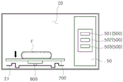
图12a和图12b是示出如何根据本发明实施方式的微波炉中的食物的初始温度手动调节托盘的高度的视图。图12a和图12b示出由用户根据食物的状态手动调节托盘200的高度的情况。在控制面板50上可形成有至少一个调节按钮500。图12a和图12b的附图标记800表示“托盘支承件”。托盘支承件800支承托盘200,并且能够同时在竖直方向上移动。托盘支承件800可包括弹簧阻尼器、气压缸等。12a and 12b are views showing how to manually adjust the height of the tray according to the initial temperature of the food in the microwave oven according to the embodiment of the present invention. 12a and 12b illustrate the case where the height of the
可根据放置在托盘200上的食物的状态改变托盘200的高度。食物的状态包括食物的类型、食物的重量、食物的密度、食物的初始温度等。The height of the
如图12a和图12b中所示,托盘200的高度可根据放置在托盘200上的食物的初始温度来手动调节。如图12a中所示,当食物的初始温度低时,减小烹饪室20的底表面21与托盘200之间的距离。换言之,减小托盘200的高度。这里,当食物的初始温度低于-15℃时,食物的初始温度被称为低。如图12b中所示,当食物的初始温度高时,增大烹饪室20的底表面21与托盘200之间的距离。换言之,增大托盘200的高度。这是因为,当食物的初始温度较低时,加热食物花费更久。通过减小托盘200与烹饪室20的底表面21之间的距离,从烹饪室20的底表面21反射的微波辐射可更有效地传输至食物。As shown in Figures 12a and 12b, the height of the
当用户想要根据食物的初始温度手动调节托盘200的高度时,用户可选择第一调节按钮501。如果用户选择第一调节按钮501,则操作用于食物的温度检测传感器(未示出)以测量食物的温度。根据结果来调节托盘200的高度。When the user wants to manually adjust the height of the
此外,可根据放置在托盘200上的食物的密度来手动调节托盘200的高度。当食物的密度低时,增大烹饪室20的底表面21与托盘200之间的距离。换言之,增大托盘200的高度。当食物的密度高时,减小烹饪室20的底表面21与托盘200之间的距离。换言之,减小托盘200的高度。这是因为,当食物的密度较高时加热食物花费更久。通过减小托盘200与烹饪室20的底表面21之间的距离,从烹饪室20的底表面21反射的微波辐射可更有效地传输至食物。In addition, the height of the
当用户想要根据食物的密度手动调节托盘200的高度时,用户可选择第二调节按钮502。如果用户选择第二调节按钮502,则操作用于食物的密度检测传感器(未示出)以测量食物的密度。根据结果来调节托盘200的高度。When the user wants to manually adjust the height of the
低密度食物可包括例如水果或蔬菜。高密度食物可例如包括肉。Low-density foods may include, for example, fruits or vegetables. High-density foods may, for example, include meat.
此外,可根据放置在托盘200上的食物的重量手动调节托盘200的高度。当食物的重量小时,增大烹饪室20的底表面21与托盘200之间的距离。换言之,增大托盘200的高度。当食物的重量大时,减小烹饪室20的底表面21与托盘200之间的距离。换言之,减小托盘200的高度。这是因为,当食物的重量较大时加热食物花费更久。通过减小托盘200与烹饪室20的底表面21之间的距离,从烹饪室20的底表面21反射的微波辐射可更有效地传输至食物。In addition, the height of the
当用户想要根据食物的重量手动调节托盘200的高度时,用户可选择第三调节按钮503。如果用户选择第三调节按钮503,则操作用于食物的重量检测传感器(未示出)以测量食物的重量。根据结果来调节托盘200的高度。When the user wants to manually adjust the height of the
当用户选择调节按钮500时,不仅可调节托盘200的高度而且还可调节图案的宽度、高度、深度等。When the user selects the
图13是示出如何在根据本发明实施方式的微波炉中自动地调节托盘的高度的视图。图13作为示例示出应用弹簧阻尼器600的情况。13 is a view showing how the height of the tray is automatically adjusted in the microwave oven according to the embodiment of the present invention. FIG. 13 shows a case where the
如图13中所示,可根据放置在托盘200上的食物的状态改变托盘200的高度。食物的状态包括食物的类型、食物的重量、食物的密度、食物的初始温度等。As shown in FIG. 13 , the height of the
当食物的重量小时、当食物的密度低时或者当食物的初始温度高时,增大烹饪室20的底表面21与托盘200之间的距离。换言之,增大托盘200的高度。相反,当食物的重量大时、当食物的密度高时或者当食物的初始温度低时,减小烹饪室20的底表面21与托盘200之间的距离。换言之,减小托盘200的高度。这是因为,当食物的重量较大、食物的密度较高或者食物的初始温度较低时,加热食物花费更久。通过减小托盘200与烹饪室20的底表面21之间的距离,从烹饪室20的底表面21反射的微波辐射可更有效地传输至食物。When the weight of the food is small, when the density of the food is low, or when the initial temperature of the food is high, the distance between the
可根据食物的状态自动调节托盘200的高度。此时,作为示例,可使用弹簧阻尼器600来调节托盘200的高度。The height of the
在微波炉1中可安装有能够测量食物的状态的相机和传感器中的至少一个。作为示例,相机和传感器中的至少一个可安装在烹饪室20中。传感器可包括温度检测传感器、密度检测传感器、重量检测传感器等。图13作为示例示出相机70安装在烹饪室20中的情况。At least one of a camera and a sensor capable of measuring the state of food may be installed in the
当用户将食物放置在托盘200上并且操作微波炉1时,相机和传感器中的至少一个测量食物的状态。当完成对食物的状态的测量时,根据结果自动调节托盘200的高度。此时,不仅可自动调节托盘200的高度,还可自动调节图案的宽度、高度、深度等。When the user places food on the
图14是示出根据本发明另一实施方式的微波炉的剖视图。在下文中,将省略对图1至图13的描述的重复。14 is a cross-sectional view illustrating a microwave oven according to another embodiment of the present invention. Hereinafter, the repetition of the description of FIGS. 1 to 13 will be omitted.
如图14中所示,托盘200可固定在烹饪室20中。托盘200可由绝缘材料形成。As shown in FIG. 14 , the
包括第一反射部分110和第二反射部分120中的至少之一的图案可形成在烹饪室20的底表面21上。烹饪室20的底表面21的部分21a能够可旋转地进行安装。具体地,烹饪室20的底表面21的部分21a可安装成能够绕穿过烹饪室20的底表面21的几何中心O的竖直轴线Y旋转。包括第一反射部分110和第二反射部分120中的至少之一的图案可形成在烹饪室20的底表面21的部分21a处。A pattern including at least one of the
图15是示出根据本发明其他实施方式的微波炉的剖视图。在下文中,将省略对图1至图13的描述的重复。15 is a cross-sectional view illustrating a microwave oven according to other embodiments of the present invention. Hereinafter, the repetition of the description of FIGS. 1 to 13 will be omitted.
如图15中所示,微波炉1还可包括板900。As shown in FIG. 15 , the
板900可由微波辐射能够透过的材料形成。作为示例,板900可由玻璃材料形成。
板900可设置在托盘200与烹饪室20的底表面21的至少一部分之间。具体地,板900可设置在托盘200与烹饪室20的、其上形成有第一反射部分110和第二反射部分120中的至少之一的底表面21之间。The
另一方面,板900可设置在烹饪室20的底表面21上方。具体地,板900可设置在托盘200与烹饪室20的、其上形成有第一反射部分110和第二反射部分120中的至少之一的底表面21之间。On the other hand, the
图15作为示例示出了板900设置在烹饪室20的、其上形成有第二反射部分120的底表面21上的情况。在这种情况中,可旋转地支承托盘200的多个轮300可在板900上运动。FIG. 15 shows, as an example, a case where the
通过这种方式,板900设置在托盘200与烹饪室20的、其上形成有第一反射部分110和第二反射部分120中的至少之一的底表面21之间。由此,能够防止第一反射部分110和第二反射部分120中的至少之一被外来杂质污染。外来杂质可包括灰尘、食物等。In this way, the
多个板900可设置在托盘200与烹饪室20的底表面21的至少一部分之间。A plurality of
在上文中,食物是能够通过微波辐射加热的对象的示例。In the above, food is an example of an object that can be heated by microwave radiation.
虽然已经示出和描述了本发明的特定实施方式,但是本领域技术人员应理解,在没有脱离本发明的原理和精神的情况下,可在这些实施方式中做出改变,其中,本发明的范围在权利要求及其等同中限定。While particular embodiments of the present invention have been shown and described, it will be understood by those skilled in the art that changes may be made in these embodiments without departing from the principle and spirit of the invention, wherein the The scope is defined in the claims and their equivalents.
Claims (14)
Applications Claiming Priority (5)
| Application Number | Priority Date | Filing Date | Title |
|---|---|---|---|
| RURU2016107376 | 2016-03-01 | ||
| RU2016107376A RU2646616C2 (en) | 2016-03-01 | 2016-03-01 | Microwave oven |
| KR1020160163264A KR102747188B1 (en) | 2016-03-01 | 2016-12-02 | Microwave oven |
| KR10-2016-0163264 | 2016-12-02 | ||
| PCT/KR2017/002209 WO2017150892A1 (en) | 2016-03-01 | 2017-02-28 | Microwave oven |
Publications (2)
| Publication Number | Publication Date |
|---|---|
| CN108370619A CN108370619A (en) | 2018-08-03 |
| CN108370619B true CN108370619B (en) | 2020-12-15 |
Family
ID=59798860
Family Applications (1)
| Application Number | Title | Priority Date | Filing Date |
|---|---|---|---|
| CN201780004503.8A Expired - Fee Related CN108370619B (en) | 2016-03-01 | 2017-02-28 | Micro-wave oven |
Country Status (4)
| Country | Link |
|---|---|
| EP (1) | EP3366082A4 (en) |
| KR (1) | KR102747188B1 (en) |
| CN (1) | CN108370619B (en) |
| RU (1) | RU2646616C2 (en) |
Citations (12)
| Publication number | Priority date | Publication date | Assignee | Title |
|---|---|---|---|---|
| US4036151A (en) * | 1972-05-26 | 1977-07-19 | Sharp Kabushiki Kaisha | Microwave cooking apparatus with turntable |
| US4615405A (en) * | 1985-04-16 | 1986-10-07 | Sharp Kabushiki Kaisha | Food weight measuring device for a cooking appliance |
| GB2183980A (en) * | 1985-12-10 | 1987-06-10 | Gold Star Co | Uniform field microwave oven |
| US4683362A (en) * | 1984-09-21 | 1987-07-28 | Yangas Roger A | Reflective apparatus for microwave cooking |
| EP0274164A1 (en) * | 1987-01-08 | 1988-07-13 | Philips Norden AB | A microwave oven |
| US4808781A (en) * | 1988-03-16 | 1989-02-28 | Liu Yiu Ching | Directly driven microwave oven turntable top |
| GB2244193A (en) * | 1990-05-09 | 1991-11-20 | Samsung Electronics Co Ltd | A microwave oven |
| JPH0566019A (en) * | 1991-09-06 | 1993-03-19 | Matsushita Electric Ind Co Ltd | High-frequency heating apparatus |
| CN1083301A (en) * | 1992-08-25 | 1994-03-02 | 株式会社金星社 | The Wave guide system of microwave oven |
| US5828042A (en) * | 1996-07-11 | 1998-10-27 | Lg Electronics Inc. | Uniform heating apparatus for microwave oven and method thereof |
| JP2002327983A (en) * | 2001-05-01 | 2002-11-15 | Anzai Setsu | Microwave drying apparatus |
| CN104853465A (en) * | 2015-04-10 | 2015-08-19 | 云南师范大学 | Microwave oven heating chamber structure equipped with microwave lenses |
Family Cites Families (7)
| Publication number | Priority date | Publication date | Assignee | Title |
|---|---|---|---|---|
| KR900003489B1 (en) * | 1987-03-14 | 1990-05-19 | 삼성전자 주식회사 | Microwave Disperser |
| JP3066283B2 (en) * | 1995-03-13 | 2000-07-17 | 三洋電機株式会社 | microwave |
| KR100206366B1 (en) * | 1996-12-27 | 1999-07-01 | 전주범 | Microwave dispersion structure for microwave oven |
| KR100395559B1 (en) * | 1999-05-29 | 2003-08-25 | 삼성전자주식회사 | Microwave oven having a heater |
| CA2398649C (en) * | 2001-02-05 | 2005-06-21 | Young Hee Lee | Apparatus for uniformly dispersing microwave and heating system using the same |
| JP4028817B2 (en) * | 2003-05-20 | 2007-12-26 | シャープ株式会社 | Heat cooker weight measuring device |
| US20090139988A1 (en) * | 2007-12-03 | 2009-06-04 | Farnworth Warren M | System for creating more uniform distribution of microwave energy in a cavity |
-
2016
- 2016-03-01 RU RU2016107376A patent/RU2646616C2/en active
- 2016-12-02 KR KR1020160163264A patent/KR102747188B1/en active Active
-
2017
- 2017-02-28 EP EP17760296.8A patent/EP3366082A4/en not_active Withdrawn
- 2017-02-28 CN CN201780004503.8A patent/CN108370619B/en not_active Expired - Fee Related
Patent Citations (12)
| Publication number | Priority date | Publication date | Assignee | Title |
|---|---|---|---|---|
| US4036151A (en) * | 1972-05-26 | 1977-07-19 | Sharp Kabushiki Kaisha | Microwave cooking apparatus with turntable |
| US4683362A (en) * | 1984-09-21 | 1987-07-28 | Yangas Roger A | Reflective apparatus for microwave cooking |
| US4615405A (en) * | 1985-04-16 | 1986-10-07 | Sharp Kabushiki Kaisha | Food weight measuring device for a cooking appliance |
| GB2183980A (en) * | 1985-12-10 | 1987-06-10 | Gold Star Co | Uniform field microwave oven |
| EP0274164A1 (en) * | 1987-01-08 | 1988-07-13 | Philips Norden AB | A microwave oven |
| US4808781A (en) * | 1988-03-16 | 1989-02-28 | Liu Yiu Ching | Directly driven microwave oven turntable top |
| GB2244193A (en) * | 1990-05-09 | 1991-11-20 | Samsung Electronics Co Ltd | A microwave oven |
| JPH0566019A (en) * | 1991-09-06 | 1993-03-19 | Matsushita Electric Ind Co Ltd | High-frequency heating apparatus |
| CN1083301A (en) * | 1992-08-25 | 1994-03-02 | 株式会社金星社 | The Wave guide system of microwave oven |
| US5828042A (en) * | 1996-07-11 | 1998-10-27 | Lg Electronics Inc. | Uniform heating apparatus for microwave oven and method thereof |
| JP2002327983A (en) * | 2001-05-01 | 2002-11-15 | Anzai Setsu | Microwave drying apparatus |
| CN104853465A (en) * | 2015-04-10 | 2015-08-19 | 云南师范大学 | Microwave oven heating chamber structure equipped with microwave lenses |
Also Published As
| Publication number | Publication date |
|---|---|
| EP3366082A1 (en) | 2018-08-29 |
| KR20170102413A (en) | 2017-09-11 |
| CN108370619A (en) | 2018-08-03 |
| RU2646616C2 (en) | 2018-03-06 |
| RU2016107376A (en) | 2017-09-04 |
| EP3366082A4 (en) | 2018-12-19 |
| KR102747188B1 (en) | 2024-12-31 |
Similar Documents
| Publication | Publication Date | Title |
|---|---|---|
| US10986705B2 (en) | Microwave oven | |
| JP6004281B2 (en) | Microwave heating device | |
| CN100493271C (en) | High-frequency heating apparatus | |
| KR100565656B1 (en) | Microwave | |
| JP2009156546A (en) | Cooker | |
| WO2011140258A1 (en) | Oven circulating heated air | |
| WO2009084169A1 (en) | Cooking device | |
| JPH10106741A (en) | Waveguide system of electronic oven | |
| US11191134B2 (en) | Microwave heating apparatus with rotatable antenna and method thereof | |
| SG192170A1 (en) | High-frequency heating apparatus | |
| CN108370619B (en) | Micro-wave oven | |
| JPS6337472B2 (en) | ||
| JP5492646B2 (en) | Induction heating cooker | |
| US20230180358A1 (en) | Cooker | |
| KR101932046B1 (en) | Cooking apparatus using microwaves | |
| KR101543659B1 (en) | Microwave range having a convection function | |
| KR101885654B1 (en) | Cooking apparatus using microwaves | |
| CN109417839B (en) | Multi-feed microwave oven with improved crisping | |
| CN211600805U (en) | Microwave oven capable of preventing electromagnetic wave leakage | |
| JP5957680B2 (en) | Microwave heating device | |
| JP3910116B2 (en) | High frequency heating device | |
| JPS6332235B2 (en) | ||
| KR100657480B1 (en) | Microwave | |
| JP4966648B2 (en) | Microwave heating device | |
| KR200182324Y1 (en) | A heat reflecting device in multifunctional microwave oven |
Legal Events
| Date | Code | Title | Description |
|---|---|---|---|
| PB01 | Publication | ||
| PB01 | Publication | ||
| SE01 | Entry into force of request for substantive examination | ||
| SE01 | Entry into force of request for substantive examination | ||
| GR01 | Patent grant | ||
| GR01 | Patent grant | ||
| CF01 | Termination of patent right due to non-payment of annual fee |
Granted publication date: 20201215 |
|
| CF01 | Termination of patent right due to non-payment of annual fee |