CN108398576B - Static error calibration system and method - Google Patents
Static error calibration system and method Download PDFInfo
- Publication number
- CN108398576B CN108398576B CN201810181130.8A CN201810181130A CN108398576B CN 108398576 B CN108398576 B CN 108398576B CN 201810181130 A CN201810181130 A CN 201810181130A CN 108398576 B CN108398576 B CN 108398576B
- Authority
- CN
- China
- Prior art keywords
- acceleration sensor
- axis
- contact
- static error
- water platform
- Prior art date
- Legal status (The legal status is an assumption and is not a legal conclusion. Google has not performed a legal analysis and makes no representation as to the accuracy of the status listed.)
- Active
Links
- 230000003068 static effect Effects 0.000 title claims abstract description 99
- 238000000034 method Methods 0.000 title claims abstract description 33
- 230000001133 acceleration Effects 0.000 claims abstract description 94
- XLYOFNOQVPJJNP-UHFFFAOYSA-N water Substances O XLYOFNOQVPJJNP-UHFFFAOYSA-N 0.000 claims abstract description 59
- 238000005259 measurement Methods 0.000 claims abstract description 58
- 238000012545 processing Methods 0.000 claims description 3
- 230000006870 function Effects 0.000 description 30
- 238000010586 diagram Methods 0.000 description 7
- 238000004458 analytical method Methods 0.000 description 3
- 238000013461 design Methods 0.000 description 3
- 239000011159 matrix material Substances 0.000 description 3
- 230000000694 effects Effects 0.000 description 2
- 238000004519 manufacturing process Methods 0.000 description 2
- 238000004364 calculation method Methods 0.000 description 1
- 238000011161 development Methods 0.000 description 1
- 238000005516 engineering process Methods 0.000 description 1
- 230000007613 environmental effect Effects 0.000 description 1
- 238000001914 filtration Methods 0.000 description 1
- 230000014509 gene expression Effects 0.000 description 1
- 230000005484 gravity Effects 0.000 description 1
- 238000012544 monitoring process Methods 0.000 description 1
- 230000008447 perception Effects 0.000 description 1
- 230000000750 progressive effect Effects 0.000 description 1
Images


Classifications
-
- G—PHYSICS
- G01—MEASURING; TESTING
- G01P—MEASURING LINEAR OR ANGULAR SPEED, ACCELERATION, DECELERATION, OR SHOCK; INDICATING PRESENCE, ABSENCE, OR DIRECTION, OF MOVEMENT
- G01P21/00—Testing or calibrating of apparatus or devices covered by the preceding groups
-
- G—PHYSICS
- G01—MEASURING; TESTING
- G01C—MEASURING DISTANCES, LEVELS OR BEARINGS; SURVEYING; NAVIGATION; GYROSCOPIC INSTRUMENTS; PHOTOGRAMMETRY OR VIDEOGRAMMETRY
- G01C25/00—Manufacturing, calibrating, cleaning, or repairing instruments or devices referred to in the other groups of this subclass
- G01C25/005—Manufacturing, calibrating, cleaning, or repairing instruments or devices referred to in the other groups of this subclass initial alignment, calibration or starting-up of inertial devices
Landscapes
- Engineering & Computer Science (AREA)
- Physics & Mathematics (AREA)
- General Physics & Mathematics (AREA)
- Manufacturing & Machinery (AREA)
- Radar, Positioning & Navigation (AREA)
- Remote Sensing (AREA)
- Force Measurement Appropriate To Specific Purposes (AREA)
Abstract
本发明公开一种静态误差标定系统及方法,所述标定系统包括:三轴加速度传感器、辅助装置、水平台面;先将三轴加速度传感器放置在水平台面上,获得六个位置;然后将三轴加速度传感器放置在辅助装置上,辅助装置放置在水平台面上,获得三个位置;获取三轴加速度传感器在9个位置处于不同姿态的多组测量数据,根据9组不同测量数据实现全方面标定三轴加速度传感器的静态误差,不仅提高了标定静态误差的精度,还摆脱了依托转台和精确水平面进行静态误差标定,所需设备仅为一水平台面和本发明设计的标定辅助装置即可,降低标定系统的体积和成本。
The invention discloses a static error calibration system and method. The calibration system includes: a three-axis acceleration sensor, an auxiliary device, and a water platform; firstly, the three-axis acceleration sensor is placed on the water platform to obtain six positions; The acceleration sensor is placed on the auxiliary device, and the auxiliary device is placed on the surface of the water platform to obtain three positions; obtain multiple sets of measurement data of the three-axis acceleration sensor in different attitudes at 9 positions, and realize all-round calibration according to the 9 sets of different measurement data. The static error of the shaft acceleration sensor not only improves the accuracy of calibrating the static error, but also gets rid of the static error calibration relying on the turntable and the precise horizontal plane. System size and cost.
Description
技术领域technical field
本发明涉及加速度误差标定技术领域,特别是涉及一种静态误差标定系统及方法。The invention relates to the technical field of acceleration error calibration, in particular to a static error calibration system and method.
背景技术Background technique
加速度传感器是一种非常重要的惯性传感器,在惯性导航、姿态测量、振动监测等领域发挥着核心作用。随着微机电系统(Micro Electro-Mechanical Systems)技术的飞速发展,MEMS三轴加速度传感器以其体积小、重量轻、功耗低、成本低和可靠性高等优点被大量应用于手机、平衡车、无人机、运动捕捉、虚拟现实等众多领域。其中应用最广泛的是MEMS三轴加速度传感器组合,能够实现载体的姿态感知和辅助导航等功能。Accelerometer is a very important inertial sensor and plays a central role in inertial navigation, attitude measurement, vibration monitoring and other fields. With the rapid development of Micro Electro-Mechanical Systems (Micro Electro-Mechanical Systems) technology, MEMS triaxial accelerometers are widely used in mobile phones, balance vehicles, Drones, motion capture, virtual reality and many other fields. Among them, the most widely used is the combination of MEMS three-axis acceleration sensor, which can realize the functions of attitude perception and auxiliary navigation of the carrier.
由于受工作原理和制造工艺的影响,MEMS三轴加速度传感器的测量精度较低。特别是出厂后的MEMS三轴加速度传感器存在一系列静态误差,其静态误差包括三轴零偏、三轴刻度因子和三轴轴间交叉误差共9个误差参数。对MEMS三轴加速度传感器的标定是指采用一定的技术手段确定这9个误差参数或其中几个参数的值,如果不通过标定对这些误差的值进行确定进而补偿,MEMS三轴加速度传感器的测量精度将大打折扣,甚至影响正常的使用。Due to the influence of the working principle and manufacturing process, the measurement accuracy of the MEMS three-axis accelerometer is low. In particular, there are a series of static errors in the MEMS three-axis accelerometer after leaving the factory. The static errors include three-axis zero offset, three-axis scale factor and three-axis inter-axis cross error, a total of 9 error parameters. The calibration of the MEMS triaxial acceleration sensor refers to the use of certain technical means to determine the values of these 9 error parameters or several of them. If the values of these errors are not determined and compensated by calibration, the measurement of the MEMS triaxial acceleration sensor The accuracy will be greatly reduced, and even affect the normal use.
目前MEMS三轴加速度传感器标定绝大多数采用多位置的方法。具体包括无依托的六位置法和依托转台的六位置法。At present, most of the calibration of MEMS three-axis accelerometer adopts multi-position method. Specifically, it includes the six-position method without support and the six-position method with support on the turntable.
无依托的六位置法的具体步骤为:首先设计需要采集三轴加速度数据的六个位置;然后依次将MEMS三轴加速度传感器按六个位置放置,并采集其输出的加速度数据;最后对采集到的六个位置的数据进行处理,计算获得加速度传感器的零偏和刻度因子误差。目前大疆等无人机厂家的产品都采用无依托六位置法进行现场标定。虽然无依托六位置法对环境要求不高,仅需要一个平整的台面即可。但由于六次测量只能建立起6个包含误差参数的方程式,无法求解出全部9个误差参数,因此无依托六位置法仅能够标定三轴零偏和三轴刻度因子6个静态误差参数,无法标定轴间交叉误差,而轴间交叉误差是三轴MEMS三轴加速度传感器用于感知载体姿态时的主要误差来源,特别是对很大一部分物理正交的MEMS三轴加速度传感器而言,轴间正交性很难保证,其轴间交叉误差会比较严重。因此无依托六位置法无法标定MEMS三轴加速度传感器的全部静态误差参数,因此具有标定效果较差的问题。The specific steps of the unsupported six-position method are: first, design six positions that need to collect three-axis acceleration data; then place the MEMS three-axis acceleration sensor in six positions in turn, and collect the output acceleration data; The data of the six positions are processed, and the zero bias and scale factor errors of the acceleration sensor are obtained by calculation. At present, the products of UAV manufacturers such as DJI use the six-position method without support for on-site calibration. Although the unrelied six-position method does not require high environmental requirements, only a flat table is required. However, since six measurements can only establish 6 equations including error parameters, all 9 error parameters cannot be solved, so without relying on the six-position method, only 6 static error parameters of the three-axis zero offset and the three-axis scale factor can be calibrated. The inter-axis cross error cannot be calibrated, and the inter-axis cross error is the main source of error when the three-axis MEMS three-axis accelerometer is used to sense the attitude of the carrier, especially for a large number of physically orthogonal MEMS three-axis accelerometers. It is difficult to guarantee the orthogonality between the axes, and the crossover error between the axes will be more serious. Therefore, all static error parameters of the MEMS three-axis acceleration sensor cannot be calibrated without relying on the six-position method, so the calibration effect is poor.
依托转台的六位置法也比较常见,其步骤与无依托六位置法类似,不同在于需要将MEMS三轴加速度传感器固定于转台上,并将转台移动至设计的六个位置,采集相应数据并处理可获得加速度传感器的零偏、刻度因子和轴间交叉误差。依托转台的六位置法能够将MEMS三轴加速度传感器的每个轴与当地重力矢量对齐,能够从建立起的6个方程直接得到9个静态误差参数的解析表达式。因此依托转台的六位置法能够标定包括三轴零偏、刻度因子和轴间交叉误差在内的全部9个静态误差参数,但转台的成本非常高,且体积大、不便移动,无法用于现场标定。The six-position method based on the turntable is also relatively common. The steps are similar to the six-position method without support. The difference is that the MEMS three-axis acceleration sensor needs to be fixed on the turntable, and the turntable is moved to the six designed positions, and the corresponding data is collected and processed. The zero offset, scale factor and cross-axis error of the accelerometer can be obtained. The six-position method based on the turntable can align each axis of the MEMS three-axis acceleration sensor with the local gravity vector, and the analytical expressions of nine static error parameters can be directly obtained from the six established equations. Therefore, the six-position method based on the turntable can calibrate all 9 static error parameters including three-axis zero offset, scale factor and inter-axis cross error, but the cost of the turntable is very high, and it is bulky and inconvenient to move, so it cannot be used on site Calibration.
发明内容SUMMARY OF THE INVENTION
本发明的目的是提供一种静态误差标定系统及方法,以实现全面标定静态误差,提高标定静态误差的精度,降低标定系统的体积和成本。The purpose of the present invention is to provide a static error calibration system and method, so as to realize the comprehensive calibration of the static error, improve the accuracy of the calibration of the static error, and reduce the volume and cost of the calibration system.
为实现上述目的,本发明提供一种静态误差标定系统,所述标定系统包括:三轴加速度传感器、辅助装置、水平台面;In order to achieve the above object, the present invention provides a static error calibration system, the calibration system includes: a three-axis acceleration sensor, an auxiliary device, and a water platform;
三轴加速度传感器放置在水平台面上,获得六个位置;The three-axis acceleration sensor is placed on the water platform to obtain six positions;
三轴加速度传感器放置在辅助装置上,辅助装置放置在水平台面上,获得三个位置。The three-axis acceleration sensor is placed on the auxiliary device, and the auxiliary device is placed on the water platform to obtain three positions.
可选的,所述辅助装置包括凹槽,所述凹槽是由长方体向下凹陷形成的。Optionally, the auxiliary device includes a groove, and the groove is formed by a downward depression of a rectangular parallelepiped.
可选的,所述凹槽为“V”字形凹槽,所述“V”字形凹槽的角度为30°至60°之间的任一角度。Optionally, the groove is a "V"-shaped groove, and the angle of the "V"-shaped groove is any angle between 30° and 60°.
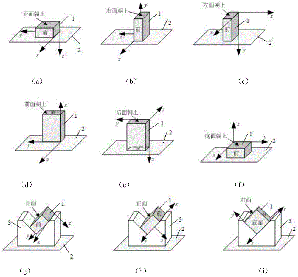
可选的,所述三轴加速度传感器放置在水平台面上,获得六个位置,具体包括:三轴加速度传感器的底面与水平台面接触放置;三轴加速度传感器的左面与水平台面接触放置;三轴加速度传感器的右面与水平台面接触放置;三轴加速度传感器的后面与水平台面接触放置;三轴加速度传感器的前面与水平台面接触放置;三轴加速度传感器的正面与水平台面接触放置;Optionally, the three-axis acceleration sensor is placed on the water platform to obtain six positions, which specifically include: the bottom surface of the three-axis acceleration sensor is placed in contact with the water platform surface; the left side of the three-axis acceleration sensor is placed in contact with the water platform surface; the three-axis acceleration sensor is placed in contact with the water platform surface; The right side of the acceleration sensor is placed in contact with the water platform surface; the back of the triaxial acceleration sensor is placed in contact with the water platform surface; the front of the triaxial acceleration sensor is placed in contact with the water platform surface; the front of the triaxial acceleration sensor is placed in contact with the water platform surface;
所述三轴加速度传感器放置在辅助装置上,辅助装置放置在水平台面上,获得三个位置,具体包括:三轴加速度传感器的底面和右面分别与辅助装置的凹槽接触放置;三轴加速度传感器的底面和后面与辅助装置的凹槽接触放置;三轴加速度传感器的后面和左面分别与辅助装置的凹槽接触放置。The three-axis acceleration sensor is placed on the auxiliary device, and the auxiliary device is placed on the water platform to obtain three positions, which specifically include: the bottom surface and the right side of the three-axis acceleration sensor are respectively placed in contact with the groove of the auxiliary device; the three-axis acceleration sensor is placed in contact with the groove of the auxiliary device; The bottom and back of the sensor are placed in contact with the groove of the auxiliary device; the rear and left sides of the three-axis accelerometer are placed in contact with the groove of the auxiliary device respectively.
本发明还提供一种静态误差标定方法,所述方法包括:The present invention also provides a static error calibration method, the method comprising:
分别获取三轴加速度传感器在各位置的m组测量数据;Obtain m groups of measurement data of the three-axis accelerometer at each position respectively;
根据三轴加速度传感器在各位置的m组测量数据确定各位置的均值向量;Determine the mean value vector of each position according to the m groups of measurement data of the three-axis acceleration sensor at each position;
获取初始静态误差参数向量;Get the initial static error parameter vector;
根据初始静态误差参数向量和各位置的均值向量确定各位置的测量误差函数;Determine the measurement error function of each position according to the initial static error parameter vector and the mean value vector of each position;
根据各位置的测量误差函数确定当前静态误差参数向量;Determine the current static error parameter vector according to the measurement error function of each position;
根据当前静态误差参数向量和各位置的测量误差函数确定代价函数值;Determine the cost function value according to the current static error parameter vector and the measurement error function of each position;
判断代价函数值是否小于设定阈值;如果代价函数值小于设定阈值,则将当前静态误差参数向量作为最优静态误差参数向量,输出最优静态误差参数向量;如果代价函数值大于等于设定阈值,则将当前静态误差参数向量作为初始静态误差参数向量,重新确定当前静态误差参数向量。Determine whether the cost function value is less than the set threshold; if the cost function value is less than the set threshold, the current static error parameter vector is used as the optimal static error parameter vector, and the optimal static error parameter vector is output; if the cost function value is greater than or equal to the set value If the threshold is set, the current static error parameter vector is used as the initial static error parameter vector, and the current static error parameter vector is re-determined.
可选的,所述根据三轴加速度传感器各位置的m组测量数据确定各位置的均值向量,具体包括:Optionally, determining the mean value vector of each position according to m groups of measurement data of each position of the three-axis acceleration sensor specifically includes:
对所述在各位置的m组测量数据进行剔除野值处理,获得各位置的n组预处理数据;其中,n为小于等于m的整数;Perform outlier processing on the m groups of measurement data at each position to obtain n groups of preprocessed data at each position; wherein, n is an integer less than or equal to m;
根据各位置的n组预处理数据确定各位置的均值向量。The mean vector of each location is determined according to the n sets of preprocessed data at each location.
可选的,所述根据初始静态误差参数向量和各位置的均值向量确定各位置的测量误差函数,具体包括:Optionally, determining the measurement error function of each position according to the initial static error parameter vector and the mean value vector of each position specifically includes:
根据初始静态误差参数向量和各位置的均值向量确定各位置的静态误差参数模型;Determine the static error parameter model of each position according to the initial static error parameter vector and the mean value vector of each position;
根据各位置的静态误差参数模型确定各位置的测量误差函数。The measurement error function of each position is determined according to the static error parameter model of each position.
可选的,所述根据各位置的测量误差函数确定当前静态误差参数向量,具体包括:Optionally, determining the current static error parameter vector according to the measurement error function of each position specifically includes:
根据各位置的测量误差函数确定测量误差向量;Determine the measurement error vector according to the measurement error function of each position;
根据初始静态误差参数向量和测量误差向量确定当前静态误差参数向量。The current static error parameter vector is determined according to the initial static error parameter vector and the measurement error vector.
可选的,所述各个位置具体包括:Optionally, the respective locations specifically include:
三轴加速度传感器的底面与水平台面接触放置;三轴加速度传感器的左面与水平台面接触放置;三轴加速度传感器的右面与水平台面接触放置;三轴加速度传感器的后面与水平台面接触放置;三轴加速度传感器的前面与水平台面接触放置;三轴加速度传感器的正面与水平台面接触放置;三轴加速度传感器的底面和右面分别与辅助装置的凹槽接触放置;三轴加速度传感器的底面和后面与辅助装置的凹槽接触放置;三轴加速度传感器的后面和左面分别与辅助装置的凹槽接触放置。The bottom surface of the triaxial acceleration sensor is placed in contact with the water platform surface; the left surface of the triaxial acceleration sensor is placed in contact with the water platform surface; the right surface of the triaxial acceleration sensor is placed in contact with the water platform surface; the rear of the triaxial acceleration sensor is placed in contact with the water platform surface; the triaxial acceleration sensor is placed in contact with the water platform surface; The front of the accelerometer is placed in contact with the water platform; the front of the triaxial accelerometer is placed in contact with the water platform; the bottom and right sides of the triaxial accelerometer are placed in contact with the grooves of the auxiliary device respectively; the bottom and rear of the triaxial accelerometer are placed in contact with the auxiliary The groove of the device is placed in contact; the rear and left sides of the triaxial acceleration sensor are placed in contact with the groove of the auxiliary device respectively.
根据本发明提供的具体实施例,本发明公开了以下技术效果:According to the specific embodiments provided by the present invention, the present invention discloses the following technical effects:
本发明设计辅助装置,先将三轴加速度传感器放置在水平台面上,获得六个位置;然后将三轴加速度传感器放置在辅助装置上,辅助装置放置在水平台面上,获得三个位置;获取三轴加速度传感器在9个位置处于不同姿态的多组测量数据,根据9组不同测量数据实现全方面标定三轴加速度传感器的静态误差,不仅提高了标定静态误差的精度,还摆脱了依托转台和精确水平面进行静态误差标定,所需设备仅为一水平台面和本发明设计的标定辅助装置即可,降低标定系统的体积和成本。The invention designs an auxiliary device, firstly placing the three-axis acceleration sensor on the water platform to obtain six positions; then placing the three-axis acceleration sensor on the auxiliary device, and placing the auxiliary device on the water platform to obtain three positions; The three-axis acceleration sensor has multiple sets of measurement data in different attitudes at 9 positions. According to 9 sets of different measurement data, the static error of the three-axis acceleration sensor can be calibrated in all aspects. The static error calibration on the horizontal plane requires only a water platform plane and the calibration auxiliary device designed in the present invention, which reduces the volume and cost of the calibration system.
附图说明Description of drawings
为了更清楚地说明本发明实施例或现有技术中的技术方案,下面将对实施例中所需要使用的附图作简单地介绍,显而易见地,下面描述中的附图仅仅是本发明的一些实施例,对于本领域普通技术人员来讲,在不付出创造性劳动性的前提下,还可以根据这些附图获得其他的附图。In order to more clearly illustrate the embodiments of the present invention or the technical solutions in the prior art, the accompanying drawings required in the embodiments will be briefly introduced below. Obviously, the drawings in the following description are only some of the present invention. In the embodiments, for those of ordinary skill in the art, other drawings can also be obtained according to these drawings without creative labor.
图1为本发明实施例静态误差标定系统结构图;1 is a structural diagram of a static error calibration system according to an embodiment of the present invention;
图2为本发明实施例静态误差标定系统坐标分析图;2 is a coordinate analysis diagram of a static error calibration system according to an embodiment of the present invention;
图3为本发明实施例辅助装置结构示意图;3 is a schematic structural diagram of an auxiliary device according to an embodiment of the present invention;
图4为本发明实施例静态误差标定方法流程图。FIG. 4 is a flowchart of a static error calibration method according to an embodiment of the present invention.
其中,1、三轴加速度传感器,2、水平台面,3、辅助装置。Among them, 1. three-axis acceleration sensor, 2. water platform, 3. auxiliary device.
具体实施方式Detailed ways
下面将结合本发明实施例中的附图,对本发明实施例中的技术方案进行清楚、完整地描述,显然,所描述的实施例仅仅是本发明一部分实施例,而不是全部的实施例。基于本发明中的实施例,本领域普通技术人员在没有做出创造性劳动前提下所获得的所有其他实施例,都属于本发明保护的范围。The technical solutions in the embodiments of the present invention will be clearly and completely described below with reference to the accompanying drawings in the embodiments of the present invention. Obviously, the described embodiments are only a part of the embodiments of the present invention, but not all of the embodiments. Based on the embodiments of the present invention, all other embodiments obtained by those of ordinary skill in the art without creative efforts shall fall within the protection scope of the present invention.
本发明的目的是提供一种静态误差标定系统及方法,以实现全面标定静态误差,提高标定静态误差的精度,降低标定系统的体积和成本。The purpose of the present invention is to provide a static error calibration system and method, so as to realize the comprehensive calibration of the static error, improve the accuracy of the calibration of the static error, and reduce the volume and cost of the calibration system.
为使本发明的上述目的、特征和优点能够更加明显易懂,下面结合附图和具体实施方式对本发明作进一步详细的说明。In order to make the above objects, features and advantages of the present invention more clearly understood, the present invention will be described in further detail below with reference to the accompanying drawings and specific embodiments.
受工作原理和制造工艺的影响,MEMS惯性器件的测量精度受到制约,在测量输出中总是包含着各种误差项,具体包括静态误差和随机误差两类。其中随机误差包括MEMS器件受环境(如温度、湿度)、电气噪声等因素影响产生的不确定误差,需要在实际使用过程中利用滤波等方法进行抑制。静态误差包括三轴的零偏、刻度因子和轴间交叉误差,零偏误差是由于MEMS加速度传感器在零输入的情况下输出不为零而引起的误差,刻度因子误差是实际输出与说明书上不同而引起的误差,轴间交叉误差是由于工艺原因测量的三轴之间不成交而引起的误差,通过标定可确定这些误差参数的值,进而进行补偿,使加速度传感器的输出更接近真实值。Affected by the working principle and manufacturing process, the measurement accuracy of MEMS inertial devices is restricted, and various error terms are always included in the measurement output, including static errors and random errors. Among them, random errors include uncertain errors caused by MEMS devices affected by factors such as environment (such as temperature, humidity), electrical noise, etc., which need to be suppressed by filtering and other methods in the actual use process. The static error includes the zero offset of the three axes, the scale factor and the cross error between the axes. The zero offset error is the error caused by the fact that the output of the MEMS accelerometer is not zero under the condition of zero input. The scale factor error is the difference between the actual output and the specification. The error caused by the inter-axis cross error is the error caused by the non-transaction between the three axes measured due to technological reasons. The value of these error parameters can be determined by calibration, and then compensated to make the output of the acceleration sensor closer to the true value.
图1为本发明实施例静态误差标定系统结构图,其中,图1中(a)-(i)为三轴加速度传感器放置的9个不同方式;图2为本发明实施例静态误差标定系统坐标分析图,其中,图2中(a)-(i)为三轴加速度传感器不同位置的坐标分析图;如图1-图2所示,本发明提供一种静态误差标定系统,所述标定系统包括:三轴加速度传感器1、辅助装置3、水平台面2。Fig. 1 is a structural diagram of a static error calibration system according to an embodiment of the present invention, wherein (a)-(i) in Fig. 1 are 9 different ways of placing the three-axis acceleration sensor; Fig. 2 is the coordinates of the static error calibration system according to the embodiment of the present invention Analysis diagram, wherein (a)-(i) in Fig. 2 are the coordinate analysis diagrams of different positions of the three-axis acceleration sensor; as shown in Fig. 1-Fig. 2, the present invention provides a static error calibration system, the calibration system Including: three-
图3为本发明实施例辅助装置结构示意图;(a)为辅助装置立体结构示意图;(b)为辅助装置主视图;(c)为辅助装置俯视图;(d)为辅助装置右视图;如图3所示,所述辅助装置3包括凹槽,所述凹槽是由长方体向下凹陷形成的;所述凹槽为“V”字形凹槽,所述“V”字形凹槽的角度为30°至60°之间的任一角度,本发明以45°为例构件的凹槽。3 is a schematic structural diagram of an auxiliary device according to an embodiment of the present invention; (a) is a schematic three-dimensional structure of the auxiliary device; (b) is a front view of the auxiliary device; (c) is a top view of the auxiliary device; (d) is a right side view of the auxiliary device; 3, the auxiliary device 3 includes a groove, which is formed by the downward depression of a rectangular parallelepiped; the groove is a "V"-shaped groove, and the angle of the "V"-shaped groove is 30 Any angle between ° and 60°, the present invention takes 45° as the groove of the component.
三轴加速度传感器1出厂时,厂家会标出三轴加速度传感器1的敏感轴,将三轴加速度传感器1的三个敏感轴记分别为x轴,y轴,z轴,其关系满足图2,在此基础上记x轴向为三轴加速度传感器1的前面,y轴向为右面,z轴向为底面,与x轴反向为后面,与y轴反向为左面,与z轴反向为正面。When the
如图1所示,三轴加速度传感器1放置在水平台面2上,获得六个位置;具体包括:三轴加速度传感器1的底面与水平台面2接触放置;三轴加速度传感器1的左面与水平台面2接触放置;三轴加速度传感器1的右面与水平台面2接触放置;三轴加速度传感器1的后面与水平台面2接触放置;三轴加速度传感器1的前面与水平台面2接触放置;三轴加速度传感器1的正面与水平台面2接触放置;三轴加速度传感器1放置在辅助装置3上,辅助装置3放置在水平台面2上,获得三个位置。所述三轴加速度传感器1放置在辅助装置3上,辅助装置3放置在水平台面2上,获得三个位置,具体包括:三轴加速度传感器1的底面和右面分别与辅助装置3的凹槽接触放置;三轴加速度传感器1的底面和后面与辅助装置3的凹槽接触放置;三轴加速度传感器1的后面和左面分别与辅助装置3的凹槽接触放置。As shown in Figure 1, the
图4为本发明实施例静态误差标定方法流程图;如图4所示,本发明还提供一种静态误差标定方法,所述方法具体包括以下步骤:FIG. 4 is a flowchart of a static error calibration method according to an embodiment of the present invention; as shown in FIG. 4 , the present invention also provides a static error calibration method, and the method specifically includes the following steps:
步骤10:分别获取三轴加速度传感器1在各位置的m组测量数据;其中,m为大于等于10的整数。Step 10: respectively acquire m groups of measurement data of the three-
步骤20:根据三轴加速度传感器1在各位置的m组测量数据确定各位置的均值向量。Step 20: Determine the mean value vector of each position according to m groups of measurement data of the three-
步骤30:获取初始静态误差参数向量。Step 30: Obtain an initial static error parameter vector.
步骤40:根据初始静态误差参数向量和各位置的均值向量确定各位置的测量误差函数。Step 40: Determine the measurement error function of each position according to the initial static error parameter vector and the mean value vector of each position.
步骤50:根据各位置的测量误差函数确定当前静态误差参数向量。Step 50: Determine the current static error parameter vector according to the measurement error function of each position.
步骤60:根据当前静态误差参数向量和各位置的测量误差函数确定代价函数值。Step 60: Determine the cost function value according to the current static error parameter vector and the measurement error function of each position.
步骤70:判断代价函数值是否小于设定阈值;如果代价函数值小于设定阈值,则将当前静态误差参数向量作为最优静态误差参数向量,输出最优静态误差参数向量;如果代价函数值大于等于设定阈值,则将当前静态误差参数向量作为初始静态误差参数向量,重新确定各位置的测量误差函数。Step 70: Determine whether the cost function value is less than the set threshold; if the cost function value is less than the set threshold, use the current static error parameter vector as the optimal static error parameter vector, and output the optimal static error parameter vector; if the cost function value is greater than If it is equal to the set threshold, the current static error parameter vector is used as the initial static error parameter vector, and the measurement error function of each position is re-determined.
下面对给个步骤进行详细论述:The steps are described in detail below:
步骤10:分别获取三轴加速度传感器在各位置的m组测量数据;其中,m为大于等于10的整数。本发明获取测量数据的个数以及获取测量数据的频率根据实际需求确定。Step 10: respectively acquire m groups of measurement data of the three-axis acceleration sensor at each position; wherein, m is an integer greater than or equal to 10. The present invention acquires the number of measurement data and the frequency of acquiring measurement data is determined according to actual needs.
步骤20:所述根据三轴加速度传感器1在各位置的m组测量数据确定各位置的均值向量
步骤201:对所述在各位置的m组测量数据进行剔除野值处理,获得各位置的n组预处理数据;其中,n为小于等于m的整数。Step 201: Perform outlier processing on the m groups of measurement data at each position to obtain n groups of preprocessed data at each position; wherein, n is an integer less than or equal to m.
步骤202:根据各位置的n组预处理数据确定各位置的均值向量


步骤30:获取初始静态误差参数向量β(s),其中s为大于等于0的整数。Step 30: Obtain an initial static error parameter vector β(s), where s is an integer greater than or equal to 0.
当s=0时,则β(0)=(1 1 1 0 0 0 0 0 0)T,β(0)为理想无误差情况;当s=1时,则β(1)=(Sx(1) Sy(1) Sz(1) Kxy(1) Kxz(1) Kyz(1) Bx(1) By(1) Bz(1))T;当s=2时,则β(2)=(Sx(2) Sy(2) Sz(2) Kxy(2) Kxz(2) Kyz(2) Bx(2) By(2) Bz(2))T;依次类推,初始静态误差参数向量β(s)的具体公式为:β(s)=(Sx(s) Sy(s) Sz(s) Kxy(s) Kxz(s) Kyz(s) Bx(s) By(s) Bz(s))T,其中,Sx(s)、Sy(s)、Sz(s)分为第s步x轴、y轴、z轴向的零偏;Kxy(s)、Kxz(s)、Kyz(s)分为第s步xy轴、xz轴、yz轴的轴间交叉误差;Bx(s)、By(s)、Bz(s)分别为第s步x轴、y轴、z轴向的刻度因子。When s=0, then β(0)=(1 1 1 0 0 0 0 0) T , β(0) is an ideal error-free situation; when s=1, then β(1)=(S x (1) S y (1) S z (1) K xy (1) K xz (1) K yz (1) B x (1) B y (1) B z (1)) T ; when s=2 , then β(2)=(S x (2) S y (2) S z (2) K xy (2) K xz (2) K yz (2) B x (2) B y (2) B z (2)) T ; and so on, the specific formula of the initial static error parameter vector β(s) is: β(s)=(S x (s) S y (s) S z (s) K xy (s) K xz (s) K yz (s) B x (s) By (s) B z (s)) T , where S x (s), S y (s), and S z ( s) are divided into Zero offset of x-axis, y-axis, and z-axis in step s; K xy (s), K xz (s), and K yz (s) are divided into the inter-axis cross error of xy-axis, xz-axis, and yz-axis in step s ; B x (s), By (s), and B z (s) are the scale factors of the x-axis, y-axis, and z-axis of the s- th step, respectively.
步骤40:所述根据初始静态误差参数向量β(s)和各位置的均值向量

步骤401:根据初始静态误差参数向量β(s)和各位置的均值向量


步骤402:根据各位置的静态误差参数模型


其中,

步骤50:所述根据各位置的测量误差函数
步骤501:根据各位置的测量误差函数确定测量误差向量R(s);具体公式为:Step 501: According to the measurement error function of each position Determine the measurement error vector R(s); the specific formula is:

步骤502:根据初始静态误差参数向量β(s)和测量误差向量R(s)确定当前静态误差参数向量β(s+1);具体公式为:Step 502: Determine the current static error parameter vector β(s+1) according to the initial static error parameter vector β(s) and the measurement error vector R(s); the specific formula is:
β(s+1)=β(s)-(J)-1R(s);β(s+1)=β(s)-(J) -1 R(s);
其中,β(s)为初始静态误差参数向量,R(s)为测量误差向量,(J)-1为雅可比矩阵的逆矩阵,
步骤60:根据当前静态误差参数向量β(s+1)和各位置的测量误差函数

步骤70:判断代价函数值S(β(s+1))是否小于设定阈值;如果代价函数值S(β(s+1))小于设定阈值,则将当前静态误差参数向量β(s+1)作为最优静态误差参数向量,输出最优静态误差参数向量;如果代价函数值S(β(s+1))大于等于设定阈值,则将当前静态误差参数向量β(s+1)作为初始静态误差参数向量β(s),并执行步骤40。Step 70: Determine whether the cost function value S(β(s+1)) is less than the set threshold; if the cost function value S(β(s+1)) is less than the set threshold, the current static error parameter vector β(s +1) As the optimal static error parameter vector, output the optimal static error parameter vector; if the cost function value S(β(s+1)) is greater than or equal to the set threshold, the current static error parameter vector β(s+1 ) as the initial static error parameter vector β(s), and step 40 is executed.
本发明设计辅助装置3,先将三轴加速度传感器1放置在水平台面2上,获得六个位置;然后将三轴加速度传感器1放置在辅助装置3上,辅助装置3放置在水平台面2上,获得三个位置;获取三轴加速度传感器1在9个位置处于不同姿态的多组测量数据,根据9组不同测量数据实现全方面标定三轴加速度传感器1的静态误差,不仅提高了标定静态误差的精度,还摆脱了依托转台和精确水平面进行静态误差标定,所需设备仅为一水平台面2和本发明设计的标定辅助装置即可,降低标定系统的体积和成本。The present invention designs the auxiliary device 3. First, the three-
本说明书中各个实施例采用递进的方式描述,每个实施例重点说明的都是与其他实施例的不同之处,各个实施例之间相同相似部分互相参见即可。The various embodiments in this specification are described in a progressive manner, and each embodiment focuses on the differences from other embodiments, and the same and similar parts between the various embodiments can be referred to each other.
本文中应用了具体个例对本发明的原理及实施方式进行了阐述,以上实施例的说明只是用于帮助理解本发明的方法及其核心思想;同时,对于本领域的一般技术人员,依据本发明的思想,在具体实施方式及应用范围上均会有改变之处。综上所述,本说明书内容不应理解为对本发明的限制。In this paper, specific examples are used to illustrate the principles and implementations of the present invention. The descriptions of the above embodiments are only used to help understand the methods and core ideas of the present invention; meanwhile, for those skilled in the art, according to the present invention There will be changes in the specific implementation and application scope. In conclusion, the contents of this specification should not be construed as limiting the present invention.
Claims (5)


Priority Applications (1)
| Application Number | Priority Date | Filing Date | Title |
|---|---|---|---|
| CN201810181130.8A CN108398576B (en) | 2018-03-06 | 2018-03-06 | Static error calibration system and method |
Applications Claiming Priority (1)
| Application Number | Priority Date | Filing Date | Title |
|---|---|---|---|
| CN201810181130.8A CN108398576B (en) | 2018-03-06 | 2018-03-06 | Static error calibration system and method |
Publications (2)
| Publication Number | Publication Date |
|---|---|
| CN108398576A CN108398576A (en) | 2018-08-14 |
| CN108398576B true CN108398576B (en) | 2020-02-07 |
Family
ID=63091818
Family Applications (1)
| Application Number | Title | Priority Date | Filing Date |
|---|---|---|---|
| CN201810181130.8A Active CN108398576B (en) | 2018-03-06 | 2018-03-06 | Static error calibration system and method |
Country Status (1)
| Country | Link |
|---|---|
| CN (1) | CN108398576B (en) |
Families Citing this family (4)
| Publication number | Priority date | Publication date | Assignee | Title |
|---|---|---|---|---|
| DE102020215241A1 (en) * | 2020-12-02 | 2022-06-02 | Robert Bosch Gesellschaft mit beschränkter Haftung | The present invention relates to a method for calibrating a three-axis acceleration sensor. In particular, the invention relates to a method for calibrating three-axis acceleration sensors for use in smartphones, hearables or wearables. |
| CN114280332B (en) * | 2021-12-31 | 2024-04-23 | 成都路行通信息技术有限公司 | A three-axis acceleration sensor calibration method |
| CN116817962A (en) * | 2023-04-13 | 2023-09-29 | 电视电声研究所(中国电子科技集团公司第三研究所) | Calibration method and device based on nine-axis IMU |
| CN119534922A (en) * | 2024-12-24 | 2025-02-28 | 苏州贝加迪新材料有限公司 | Field calibration method for triaxial digital MEMS accelerometer |
Citations (11)
| Publication number | Priority date | Publication date | Assignee | Title |
|---|---|---|---|---|
| CN1818555A (en) * | 2006-03-29 | 2006-08-16 | 北京航空航天大学 | Microinertia measuring unit precisive calibration for installation fault angle and rating factor decoupling |
| CN101629969A (en) * | 2009-08-20 | 2010-01-20 | 北京航空航天大学 | Calibration compensation and testing method and device of output errors of low-precision optical fiber inertial measurement unit |
| EP2214030A1 (en) * | 2009-01-30 | 2010-08-04 | Research In Motion Limited | A Method for Calibrating an Accelerometer of an Electronic Device, an Accelerometer, and an Electronic Device having an Accelerometer with Improved Calibration Features |
| CN101887068A (en) * | 2010-06-01 | 2010-11-17 | 中北大学 | Calibration compensation method of three-axis vector sensor and two-axis vector sensor |
| CN101907638A (en) * | 2010-06-11 | 2010-12-08 | 北京航空航天大学 | A Calibration Method of Accelerometer in Unsupported State |
| CN201909793U (en) * | 2010-11-30 | 2011-07-27 | 重庆仙通智能仪表有限公司 | Test board of five-position line accelerometer |
| CN102636665A (en) * | 2012-04-26 | 2012-08-15 | 中国科学院微电子研究所 | A High Accuracy Calibration Method of Accelerometer in Heading Attitude Reference System Without Turntable |
| CN103852085A (en) * | 2014-03-26 | 2014-06-11 | 北京航空航天大学 | Field calibration method of optical strapdown inertial navigation system based on least square fit |
| CN105842481A (en) * | 2016-03-18 | 2016-08-10 | 重庆邮电大学 | Triaxial accelerometer calibration method based on cross in inertial navigation system |
| CN103389114B (en) * | 2013-07-23 | 2016-08-10 | 中国兵器工业集团第二一四研究所苏州研发中心 | 3 axis MEMS gyro non-orthogonal errors scaling method based on g sensitivity |
| CN106840204A (en) * | 2017-01-18 | 2017-06-13 | 清华大学 | Inertial Measurement Unit scaling method based on test platform |
-
2018
- 2018-03-06 CN CN201810181130.8A patent/CN108398576B/en active Active
Patent Citations (11)
| Publication number | Priority date | Publication date | Assignee | Title |
|---|---|---|---|---|
| CN1818555A (en) * | 2006-03-29 | 2006-08-16 | 北京航空航天大学 | Microinertia measuring unit precisive calibration for installation fault angle and rating factor decoupling |
| EP2214030A1 (en) * | 2009-01-30 | 2010-08-04 | Research In Motion Limited | A Method for Calibrating an Accelerometer of an Electronic Device, an Accelerometer, and an Electronic Device having an Accelerometer with Improved Calibration Features |
| CN101629969A (en) * | 2009-08-20 | 2010-01-20 | 北京航空航天大学 | Calibration compensation and testing method and device of output errors of low-precision optical fiber inertial measurement unit |
| CN101887068A (en) * | 2010-06-01 | 2010-11-17 | 中北大学 | Calibration compensation method of three-axis vector sensor and two-axis vector sensor |
| CN101907638A (en) * | 2010-06-11 | 2010-12-08 | 北京航空航天大学 | A Calibration Method of Accelerometer in Unsupported State |
| CN201909793U (en) * | 2010-11-30 | 2011-07-27 | 重庆仙通智能仪表有限公司 | Test board of five-position line accelerometer |
| CN102636665A (en) * | 2012-04-26 | 2012-08-15 | 中国科学院微电子研究所 | A High Accuracy Calibration Method of Accelerometer in Heading Attitude Reference System Without Turntable |
| CN103389114B (en) * | 2013-07-23 | 2016-08-10 | 中国兵器工业集团第二一四研究所苏州研发中心 | 3 axis MEMS gyro non-orthogonal errors scaling method based on g sensitivity |
| CN103852085A (en) * | 2014-03-26 | 2014-06-11 | 北京航空航天大学 | Field calibration method of optical strapdown inertial navigation system based on least square fit |
| CN105842481A (en) * | 2016-03-18 | 2016-08-10 | 重庆邮电大学 | Triaxial accelerometer calibration method based on cross in inertial navigation system |
| CN106840204A (en) * | 2017-01-18 | 2017-06-13 | 清华大学 | Inertial Measurement Unit scaling method based on test platform |
Non-Patent Citations (1)
| Title |
|---|
| 惯导平台加速度计静态多位置模观测标定方法;邱浩阳等;《导航与控制》;20130530;第12卷(第2期);第63-67页 * |
Also Published As
| Publication number | Publication date |
|---|---|
| CN108398576A (en) | 2018-08-14 |
Similar Documents
| Publication | Publication Date | Title |
|---|---|---|
| CN109813336B (en) | Calibration method for inertia measurement unit | |
| CN108398576B (en) | Static error calibration system and method | |
| TWI225154B (en) | Acceleration measuring apparatus with calibration function | |
| CN204831330U (en) | Three -axle table's attitude sensor test system | |
| US20080202199A1 (en) | Positioning System For Single Or Multi-Axis Sensitive Instrument Calibration And Calibration System For Use Therewith | |
| CN109459061A (en) | Micro inertial measurement unit scaling method, equipment and computer readable storage medium | |
| Xu et al. | A novel calibration method using six positions for MEMS triaxial accelerometer | |
| CN105371868A (en) | Error calibration and compensation method for accelerometer unit of inertially stabilized platform system | |
| CN103823084A (en) | Method for calibrating three-axis acceleration sensor | |
| CN110631605B (en) | Gyro array calibration method and system | |
| CN106813680A (en) | A kind of static demarcating method of high accuracy, high-resolution quartz immunity sensor | |
| CN105628976A (en) | Method, processor, and system for performance parameter calibration of MEMS acceleration sensor | |
| CN107390155B (en) | A magnetic sensor calibration device and method | |
| CN103389114A (en) | Non-orthogonal error calibration method for triaxial MEMS gyroscope based on g sensitivity | |
| CN111638386A (en) | Gravity field-based accelerometer scale factor nonlinearity testing method | |
| CN109443333B (en) | A Feedback Weighted Fusion Method of Gyro Array | |
| CN107044860A (en) | A kind of measurement scaling method of inertial sensor | |
| CN104677355B (en) | Virtual gyro and method based on Multi-sensor Fusion | |
| CN110988400A (en) | MEMS accelerometer combination calibration method and calibration device | |
| CN105928544A (en) | Rapid self-calibration method of micro-inertia measurement combination unit, and apparatus thereof | |
| CN114705184A (en) | Nine-axis attitude sensor integrated intelligent error compensation method based on neural network | |
| CN207515799U (en) | A kind of calibrating installation of inertia device | |
| CN116298393B (en) | Accelerometer Calibration Method Based on Frank-Wolfe Method | |
| CN108716925A (en) | A kind of scaling method and device of nine axle sensors | |
| CN113156167B (en) | Calibration method and device of triaxial accelerometer |
Legal Events
| Date | Code | Title | Description |
|---|---|---|---|
| PB01 | Publication | ||
| PB01 | Publication | ||
| SE01 | Entry into force of request for substantive examination | ||
| SE01 | Entry into force of request for substantive examination | ||
| GR01 | Patent grant | ||
| GR01 | Patent grant |