Background
The inductor comprises a magnetic core and an electrical conductor arranged to encircle a portion of the magnetic core for N turns. The magnetic core is made of a ferromagnetic material characterized by a relative magnetic permeability of mu. In operation, an alternating current flows through the turns, producing magnetic induction of the same frequency in the core.
Such inductors are used, for example, in power converters, which, as a type of electronic equipment, have the function of adapting the voltage and current delivered by a power supply to be supplied to a distribution network or a given electrical system according to specifications.
The converter comprises an electronic component which switches as a switch (active component) at a given frequency. For example, in the case of a DC/DC converter, the active element is a transistor, which is used to "chop" the input voltage periodically. To output a continuous voltage, an inductor is used to store and discharge electrical energy in each cycle and to smooth the output voltage to its average value. These so-called "passive" elements are essential in the operation of the converter, but they may represent up to 40% of the volume and cost of the converter.
It is possible to manufacture converters operating at high frequencies (for example higher than 1MHz), thanks to the use of the material GaN, which makes it possible to manufacture transistors that can be switched at very high frequencies. In theory, increasing the frequency is valuable because it can reduce the volume of the passive components of the converter, thereby reducing the size, weight, and cost of these devices. In fact, by increasing the chopping frequency, the number of electrical cycles will increase and therefore the energy delivered by the core in a given time will increase in the same proportion. Since the power of the converter remains unchanged, it is theoretically possible to reduce the volume of the magnetic inductor in a manner inversely proportional to the frequency.
An inductor compatible to operate at frequencies between 100kHz and 10MHz has an inductance value between 1 muh and 10 mH. The most suitable inductor is a monolithic inductor made of ferromagnetic material. The material is characterized by a relative magnetic permeability mur>50 and magnetic induction BS>100mT。
Ferrite type oxide materials having a spinel crystal structure have stable permeability values at high frequencies. For this reason, they are very widely used as inductor cores, in particular for high-frequency operation between 100kHz and 10 MHz. The most common chemical formula is (Mn)1-xZnxFe2O4) And (Ni)1-xZnxFe2O4). These materials are also characterized by high resistivity values, which limit losses caused by induced currents.
However, these ferromagnetic materials are susceptible to energy dissipation processes (also known as magnetic losses). The magnetic losses are dissipated as heat at all points of the core volume.
Furthermore, the current in the turns generates a magnetic field and a variable magnetic induction having the same frequency as the current comprising a continuous component and a variable component.
The peak value of the variable magnetic induction can be written as:
BDCrepresenting the continuous component and deltab/2 representing the average between the two extreme values of the variable component.
However, magnetic losses increase with frequency and peak values of magnetic induction.
One technique for reducing magnetic losses is to reduce the peak value of the magnetic induction.
A first solution consists in creating the magnetic polarization by circulating a continuous current around the magnetic core. The intensity of the continuous current is determined by applying ampere's theorem so as to produce a constant induction value and sign corresponding to the continuous component B set by the converterDCThe signs of (A) and (B) are opposite. This solution is described in document US 6388896. The magnetic core of this solution has a certain size and a certain additional cost. For example, for a small size core, there is not always room available for additional coils to be deployed.
A second solution consists in generating the magnetic polarization by means of a magnet inserted in the region of the core or arranged against one face of the core. Arranging the magnets in such a manner that the magnetic flux in the core corresponds to the continuous component BDCIn the opposite direction.
Documents EP1187150 and EP1187151a1 describe such a solution. The magnet generates a magnetic driving force that circulates magnetic flux throughout the magnetic circuit.
This solution is effective for inductors operating at low frequencies and for materials with high relative permeability (e.g. above 500). In this case, the entire magnetic flux generated by the magnet is still confined in the core, and the magnetic flux loss is low.
On the other hand, magnetic materials that can operate at frequencies above 1MHz (e.g., NiZn ferrites) are characterized by a permeability value of less than 100. In this case, the magnetic circuit has magnetic leakage at the magnets, and a portion of the magnetic flux lines generated by each magnet do not pass through the entire magnetic circuit by passing directly from one pole of the magnet through the surrounding medium back to the other. The magnetic polarization efficiency thus changes, and the value of the continuous component of the magnetic induction intensity will not be effectively reduced. Furthermore, magnetic flux lines radiate around the core, which may affect the operation of other components of the converter.
Disclosure of Invention
It is therefore an object of the present invention to provide an inductor core suitable for producing an inductor capable of operating at high frequencies (e.g. >1MHz) and exhibiting reduced magnetic losses.
The above object is achieved by an inductor core comprising a ferromagnetic material and at least one permanent magnet. The ferromagnetic material at least partially borders the magnet, extending continuously along the side wall of the magnet between the two poles of the magnet. Since the ferromagnetic material is arranged between the poles along the magnet, the magnetic flux lines coming out of the poles N of the magnet run in the ferromagnetic material all the way to the poles S. This ensures uniform polarization of the ferromagnetic material by the magnet. This makes it possible to partially or completely compensate for the continuous component of the magnetic induction in the magnetic core in a more uniform manner. The magnetic loss can thus be effectively reduced.
When current flows in the windings, the core is the base of two magnetic circuits, one of which flows the magnetic flux lines generated by the windings and the other of which flows the magnetic flux lines generated by the magnets. The two sets of magnetic flux lines flow in opposite directions.
That is, the ferromagnetic material is arranged as close as possible to the natural path between the two stages of the magnet where the lines of magnetic flux generated by the magnet return from the north pole to the south pole. Thus, the magnetic flux lines are easily "collected". Thus, the magnetic flux lines generated by the magnets between the north and south poles have the shortest path, which will generate a uniform magnetic flux in the ferromagnetic material. Because the magnetic flux lines generated by the magnets are directed back into the ferromagnetic material, the magnetic flux lines do not radiate or radiate very little outward, and thus the operation of other components is little or not disturbed. The invention is therefore suitable for realizing an inductor in which the ferromagnetic material has a low permeability (for example less than 100) and is particularly suitable for high-frequency operation.
In one exemplary embodiment, the ferromagnetic material surrounds the entire side surface of the magnet between its two poles.
Advantageously, the dimension between the two poles of the magnet is substantially equal to the magnetic length of the core (i.e. the dimension of the ferromagnetic material). And thus little leakage.
In another advantageous exemplary embodiment, the magnetic core comprises a plurality of magnets arranged opposite to each other such that the poles of opposite polarity of two consecutive magnets face each other and the ferromagnetic material extends continuously between all the magnets. Thus, the flux lines circulate from one magnet to another and loop back between the north pole of the last magnet (in the series of magnets) and the south pole of the first magnet (in the series of magnets).
For example, the magnetic core is E-shaped and comprises a central rod with an air gap, the magnetic flux forming two loops closed in the central rod. The rod-shaped magnet is at least partially buried in the linear portion of the magnetic core, and extends over substantially the entire length of the linear portion.
The magnetic flux lines generated by the magnet loop back into the body of the core in the opposite direction to the magnetic flux lines generated by the polarization of the coil to the core. The resulting polarization will partially compensate, preferably fully compensate, for the continuous component of the magnetic induction generated by the current flow in the conductor of the inductor.
Preferably, the non-magnetic region is arranged where the two poles of the two magnets meet each other in order to avoid the magnetic flux lines to loop back before passing through the entire length of the magnetic circuit.
Advantageously, the non-magnetic region comprises a cavity through the magnetic core, said cavity also serving to drain heat to the outer surface of the magnetic core. The cavity is filled with, for example, air, and in a very advantageous manner, is filled with a material that is well thermally conductive, electrically insulating and non-magnetic, such as AIN.
The invention therefore relates to an inductor core for a magnetic inductor, comprising a body comprising a ferromagnetic material and one or more magnets, wherein the one or more magnets at least partially form a first path for circulating magnetic flux lines generated by the magnets such that the first path comprises at one end a south pole designated as a south pole end and at the other end a north pole designated as a north pole end, wherein the ferromagnetic material at least partially forms a second path for circulating the magnetic flux lines, wherein the ferromagnetic material extends continuously along the magnets from the south pole to the north pole and comprises a non-magnetic area facing the south pole end and a non-magnetic area facing the north pole end, forcing magnetic flux lines exiting from the north pole end to take the second path and to loop back at the end, the non-magnetic area being designated as "non-magnetic area end", such that a cross section of the inductor core perpendicular to the magnetic flux lines comprises the first path for circulating and a first path for circulating magnetic flux lines Both of the second path of (1).
Preferably, the direction in which the magnetic flux lines in the first path circulate is opposite to the direction in which the magnetic flux lines in the second path circulate.
In one exemplary embodiment, each magnet includes an exterior side surface between a south pole and a north pole, and the ferromagnetic material is in contact with at least a portion of the exterior side surface of each magnet.
The south and north poles of the first path may belong to a single magnet
Advantageously, the ferromagnetic material completely surrounds the outer lateral surface of the magnet, the inductor core comprising two end faces, one of which comprises a south pole and the ferromagnetic material and the other comprises a north pole and the ferromagnetic material, each end face facing a non-magnetic region designated as the end of the non-magnetic region. The ferromagnetic material may form a sleeve that houses the magnet and is in contact with an outer surface of the magnet, and wherein the distance between the poles of the magnet and the magnetic length of the core are equal or substantially equal, the non-magnetic region end being formed of air.
In another exemplary embodiment, the south and north poles of the first path belong to different magnets, the magnets being arranged such that the poles of opposite polarity of two consecutive magnets face or substantially face each other. Advantageously, the magnetic poles facing each other are connected by a zone of ferromagnetic material.
For example, the body comprises, at each region of ferromagnetic material separating two magnets with their poles facing each other, at least one non-magnetic region designated as the intermediate non-magnetic region, so as to prevent lines of magnetic flux coming out from the north pole of one magnet from looping back directly to the south pole of the magnet without impeding the lines of magnetic flux from one pole to the other of two consecutive magnets.
Each intermediate non-magnetic region may comprise a cavity. The cavities may be present on opposing outer surfaces of the body.
In one advantageous exemplary embodiment, the cavity is filled with a thermally conductive and electrically insulating material, such as AlN.
The body comprises a given thickness and the magnet may extend over the entire thickness of the body.
In one exemplary embodiment, the body includes a rectangular frame and a center bar disposed transverse to and parallel to the sides of the longest length of the frame. Two first paths are defined in the frame and in the central bar in a symmetrical manner with respect to a plane of symmetry passing through the central bar and perpendicular to a median plane of the frame, and are defined in the frame and in the central bar in a symmetrical manner with respect to the plane of symmetry. The central rod includes an air gap.
The central bar may comprise at least two magnets belonging to the two first paths.
For example, each side of longer length comprises two magnets of the same length, and each side of shorter length comprises one magnet, wherein the central bar has a magnet on each side of the air gap, such that the two first paths each comprise five magnets.
The air gap may be disposed between the south pole end and the north pole end and form a nonmagnetic region end.
Advantageously, the magnet is a bonded magnet comprising at least one powdered magnetic material dispersed in a matrix made of an electrically insulating material.
For example, the ferromagnetic material has a magnetic permeability of less than 100.
The ferromagnetic material may be spinel ferrite selected from NiZn and MnZn.
The invention also relates to an inductor comprising an inductor core according to the invention and a conductor wound around at least a part of said core.
The invention also relates to a converter comprising at least one inductor according to the invention and at least one electronic component.
The invention also relates to a method for manufacturing an inductor core according to the invention, said method comprising the steps of:
a) providing at least one magnet;
b) a body made of ferromagnetic material is manufactured by injection moulding from a starting material comprising an organic substance and at least one ferromagnetic powder, whereby at least one cavity is provided for mounting the magnet in the body.
c) Mounting the magnet in the cavity.
In step b), advantageously, at least one cavity is created to form the non-magnetic region.
The method may include the step of placing a non-magnetic, non-conductive and thermally conductive material in the cavity that forms the non-magnetic region.
In step a), advantageously, the magnet is a bonded magnet. The magnet may be manufactured by moulding a mixture of a polymer matrix and at least one magnetic powder.
Step b) may comprise a sub-step of moulding the raw material, a sub-step of debinding and a sub-step of heat treatment.
Advantageously, the substep of heat treatment occurs directly after the substep of debinding by increasing the temperature associated with debinding.
The invention also relates to another method of manufacturing an inductor core according to the invention, comprising the steps of:
a') providing at least one magnet;
b') a body made of ferromagnetic material is manufactured by over-moulding on the magnet.
Detailed Description
The inductor core according to the invention is one or more permanent magnets, but for simplicity the remainder of the description will use the term "magnet" exclusively to denote a permanent magnet.
In fig. 1A and 1B, it can be seen that one exemplary embodiment of an inductor core N1 according to the present invention includes a cylindrical body 2 having a longitudinal axis X with a circular cross-section and a magnet 6. The body 2 comprises a ferromagnetic material 4. The body has a circular cross-section and defines a cavity 8 therein with a longitudinal axis X. The cross-section and shape of the magnetic core are not limited, and for example, a body having a square cross-section falls within the scope of the present invention.
Advantageously, the magnetic core is monolithic, i.e. moulded in a single part.
The magnet 6 extends longitudinally along the X axis and has a circular cross-section. The south pole S and the north pole N of the magnet are located at the longitudinal ends of the magnet 6. The outer diameter of the magnet 6 corresponds to the inner diameter of the cavity 8, so that the magnet can be arranged in the cavity 8 and in contact with the ferromagnetic material 6. The length l1 of the magnet 6 is at least equal to the length l2 of the ferromagnetic material. In the example shown, the length l1 of the magnet is substantially equal to the length l2 of the ferromagnetic material.
It is worth noting that in this case, the region of magnetic flux that is opposite in direction to the magnetic pole of the magnet, naturally lying in line, is located outside the ferromagnetic material to achieve a rectilinear flow of magnetic flux in the core.
The ferromagnetic material 4 then surrounds the magnet 6 over the entire length of the magnet 6 and over the entire circumference. Furthermore, in the example shown, the magnets are in contact with the ferromagnetic material over the entire circumference. But embodiments in which the magnets are not in contact with the ferromagnetic material do not depart from the scope of the present invention.
The magnet generates magnetic flux lines Fm. Due to the opposite arrangement of the poles of the magnet and the ferromagnetic material, magnetic flux lines flow in the magnet 6 from the south pole S to the north pole N, whereas due to the ferromagnetic material surrounding the magnet and extending between the south pole S and the north pole N, the magnetic flux lines will loop back in the ferromagnetic material to the south pole S. The direction of the magnetic flux lines in the ferromagnetic material is opposite to the direction of the magnetic flux lines in the magnet.
All ferromagnetic material is then uniformly polarized by the magnet.
When core N1 is used to create an inductor, there is a conductor (not shown) wound around the core. For example, the conductor may be made of copper and comprise n turns on the longitudinal axis X.
A current flows in the conductor, thereby generating a magnetic field in the core and thus magnetic flux lines.
By selecting the direction of flow of current in the conductor or the direction of polarity of the magnet, the lines of magnetic flux generated by the magnet and the lines of magnetic flux generated by the conductor flow in opposite directions. By further selecting the value of the magnetic field of the magnet, the polarization produced by the magnet will reduce and advantageously eliminate the continuous component of magnetic induction produced by the current circulating in the conductor.
The peak value of the magnetic induction can be written as:
BDCrepresenting the continuous component and deltab/2 representing the average between the two extreme values of the variable component.
Magnetic causes of BDCRemoved, the peak will be equal to Δ B/2, and therefore, the peak is reduced.
However, since the magnetic loss is proportional to the peak value of the magnetic induction, the magnetic loss and the heat loss are reduced.
The structure of the magnetic core, in particular the relative arrangement of the ferromagnetic material and the magnet, enables to ensure the loop back of the magnetic flux lines in the ferromagnetic material even in case the ferromagnetic material has a low permeability (e.g. a permeability of less than 100). In fact, the ferromagnetic material is arranged around the magnet on the natural path of the lines of magnetic flux generated by the magnet going from the north pole back to the south pole. Thus, magnetization of the ferromagnetic material by the magnetic flux does not require a specific device (e.g., a polar component) to direct the magnetic flux lines into the ferromagnetic material. Even in the case of materials with low permeability, the magnetic flux lines will loop back from the north pole to the south pole of the magnet over the entire length of the ferromagnetic material and proceed in a uniform manner.
Furthermore, as shown in the example, advantageously the ferromagnetic material surrounds the entire magnet, the lines of magnetic flux loop back in a symmetrical manner around the axis of the magnet, most of the lines of magnetic flux are confined within the ferromagnetic material, and the ferromagnetic material is polarized in a uniform manner.
As a variant, the ferromagnetic material may not completely surround the magnet and only extend, for example, over a corner portion of the side surface of the magnet between the two poles. The ferromagnetic material of the core will still be polarized in a completely uniform manner and the peak will be reduced. However, a portion of the magnetic flux of the magnet may leak into the surrounding medium.
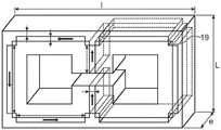
One example of a magnetic core N2 for an E-E type inductor can be seen in fig. 2A and 2B. This type of core has a high compactness.
The magnetic core N2 seen in fig. 2A described above comprises a rectangular frame 10 and a central bar 12, the longitudinal axis X' of which extends substantially perpendicular to the side of the longest length of the frame at the middle of said side. The central rod 12 should be surrounded by a plurality of turns of conductor (not shown). In the example, the bar 12 is formed by two half-bars separated by an air gap 14.
The core N2 may be formed by assembling two E-shaped half cores 15 as shown in fig. 2B, or may be directly made in one piece. As a variant, the magnetic core may also be formed by assembling an E-shaped component and an I-shaped component or a U-shaped component and an additional component.
The sides of the frame and the central bar thus define two magnetic circuits C1 and C2, which are symmetrical about a plane passing through the X axis of the central bar 12 and perpendicular to the median plane of the frame. The two magnetic circuits are rectangular. Magnetic circuits C1 and C2 are intended for the magnetic flux lines formed by the current circulating in conductor 11 to flow and loop back to the air gap. The flux lines are represented by FM3 in fig. 5.
The magnetic core N2 further includes magnets a1, a2, A3, a4, a5, a6, a7, A8 arranged in each of the magnetic circuits C1 and C2. Magnets a1 and a5 are located in the central bar 12 and are common to both magnetic circuits.
The two magnetic circuits are similar in structure, and therefore only the magnetic circuit C1 will be described in detail.
The magnetic circuit C1 comprises straight portions 16.1, 16.2, 16.3, 16.4, 16.5. The portions 16.1 and 16.5 are formed by two half-rods of the central rod 12. In the example shown, the magnet has a rectangular parallelepiped shape extending over the entire thickness of the core, the thickness of the core being considered in a direction perpendicular to the median plane of the core.
Magnet a2 extends over virtually the entire length of portion 16.2.
Magnet a3 extends over virtually the entire length of portion 16.3.
Magnet a4 extends over virtually the entire length of portion 16.4.
Magnets a1 and a5 extend virtually over the entire length of section 16.1 and section 16.5, respectively.
The magnets a1 to a5 have outer side surfaces and inner side surfaces, which are considered with respect to the inner and outer portions of the magnetic circuit C1.
As a variant, several aligned magnets may be implemented instead of a single magnet in each section.
These magnets may also form a frame that is open only at the air gap.
In the example shown, the magnets are arranged in a ferromagnetic material such that the ferromagnetic material covers the inner and outer faces of the magnets and extends continuously between the poles N and S of two consecutive magnets. In the example shown and in a preferred manner, the magnet extends over the entire thickness of the core and is flush with the front and rear surfaces of the core, which are the faces parallel to the median plane of the core. As will be described below, the core may be manufactured by molding a ferromagnetic material, during which a cavity for placing a magnet may be created.
In the example shown, the width of the magnetic material considered in the direction of the X axis is greater for the part 16.2 and the part 16.4 on the inner surface side of the magnet than for the outer surface side, but this is not a limitation and both may have the same thickness. This asymmetric arrangement of the magnets allows the connection area between the magnets to be shifted to the deflector and into the corners of the frame. The looping of the magnetic flux on each magnet occurs in areas of the inductor that are not very active, not affecting its operation.
Furthermore, the magnets are arranged relative to each other in such a way that the pole N of one magnet faces or is close to the pole S of the subsequent magnet.
Furthermore, the magnetic circuit C1 advantageously comprises deflectors located between the poles of successive magnets, for guiding the magnetic flux from one magnet to the other and isolating the magnetic flux circulating in the magnets from the magnetic flux circulating in the ferromagnetic material.
The deflector comprises for example a non-magnetic region 18 in the vicinity of the two poles of two consecutive magnets, more particularly in contact with two consecutive magnets in the interior of the frame defined by the magnets.
Advantageously, the frame comprises a cavity 19, said cavity 19 being generated in the thickness of the core and appearing on two faces of the core parallel to the median plane of the core. The cavity 19 may be empty and filled with air so that heat can be expelled to the outside of the magnetic core. In a particularly advantageous embodiment, the cavity 19 is filled with a non-magnetic, well-conducting and electrically non-conductive material, which discharges heat to the outside of the magnetic core. These cavities are filled with AIN, for example.
Preferably, the deflector has at least the same dimensions as the thickness of the magnet.
The effect caused by the presence of the magnet on magnetic circuit C1 will now be described.
The magnetic flux lines FM1 flow from pole S to pole N in magnet a1 and exit from magnet a1 through pole N. Due to the presence of the non-magnetic region 18, part of the magnetic flux enters the magnet a2 through the pole S after circulating in the ferromagnetic material. In fact, the cavity 19 prevents the magnetic flux lines from looping back directly to the pole S of the magnet a1 in the ferromagnetic material of the portion 16.1 and contributes to the uniformity of the magnetic flux.
The magnetic flux then flows into magnet a2 and to pole N, which engages pole S of magnet A3, in particular due to cavity 19, then magnet a4 and finally through magnet a5, out of pole N of magnet a5, where it then flows in the opposite direction in part 16.5, part 16.4, part 16.3, part 16.2 and part 16.1 and closes the circuit at pole S of magnet a1 due to the air gap forming the non-magnetic deflector. The magnetic flux circulating in the ferromagnetic material is called FM 2. Due to the cavity 19, the magnetic flux FM2 cannot loop back to the magnets a5, a4, A3, a 2.
Magnetic circuit C1 includes two magnetic branches, one consisting of a network of magnets and the other consisting of a ferromagnetic material that lines the magnets.
In this advantageous exemplary embodiment, the magnetic flux FM2 generated by the magnet and flowing in the magnetic material is continuous over the entire length of the magnetic path of the magnetic core. Further, the magnet extends through the entire thickness of the ferromagnetic material, and the magnetic flux is uniform through the entire thickness of the ferromagnetic material. This results in a uniformly magnetized magnetic circuit C1. The magnet may also not extend over the entire thickness of the core so that the polarisation will be less uniform but the continuous component of the induction strength will still be reduced.
It should be noted that a portion of the magnetic flux flowing from the pole N is directly looped back to the pole S of the same magnet via the external ferromagnetic material. This part of the magnetic flux that loops back via the outside of the magnet is directed in the same direction as the magnetic flux in the inner part, which therefore contributes to the continuous polarization of the outer part.
In the example shown, the cavities have a square or rectangular cross-section, but they may also have another shape, for example a circular arc cross-section extending between two consecutive magnets.
As a variant, all the magnets can be replaced by a single magnet in a single piece, forming a frame open at the air gap, which would make it possible to not have to create a non-magnetic cavity. As a variant, it is possible to make only part of the magnets in one piece, for example magnets a2 and A3, or a2, A3 and a4, etc.
In the same way a magnetic flux flow FM2 is established in the magnetic circuit C2.
The magnetic flux will be generated uniformly throughout the magnetic core.
In the example shown, the magnets a1 and a5 are common to both magnetic circuits, but it is also possible to provide a magnet dedicated to the first magnetic circuit C1 and a magnet dedicated to the second magnetic circuit C2.
When a current flows through the conductor 11 around the central bar 12, a magnetic field FM3 is generated, magnetic flux flows in both magnetic circuits and a varying magnetic induction is generated, which has a continuous component and a variable component (relationship I).
By selecting and orienting the magnets such that the generated magnetic flux cancels out a continuous component of the magnetic induction generated by the conductors in the core, it is possible to reduce the peak value of the magnetic induction generated in the core and the magnetic loss, and thus reduce the heat generation of the core. The orientation of the magnet and the flow of current through the conductor cause the magnetic flux FM2 and the magnetic flux FM3 (shown in phantom in FIG. 2A) generated by the conductor to be in opposite directions.
The invention is applicable to any form of inductor core, for example the core may be U-shaped, with the magnet extending at the bottom and two legs of the U, and magnetic flux FM2 looping back at the free ends of the legs of the U.
Preferably, the magnets are made of a non-conductive material to reduce the risk of coupling and Foucault (Foucault) currents at high frequencies, which can cause heating of the core.
Advantageously, the magnet is of the bonded or plastic magnet type. For example, the magnet includes magnetic powder dispersed in a polymer matrix or an electrically insulating resin. Advantageously, they can be moulded according to complex shapes. These magnets then have a very high resistivity. The bonded magnet may be of NdFeB type with the value BHmax of 10 MGOe. As a variant, the magnet may be made of SmCo, ferrite or SmFeN.
According to an alternative to the magnetic core of fig. 1A, the magnet 6 may be replaced by a plurality of aligned magnets, such that the pole N of one magnet faces the pole S of the other magnet. Furthermore, a deflector may be provided at the facing poles to avoid lines of magnetic flux coming out of the pole N of one magnet from looping directly back to the pole S of that magnet, rather than entering the facing pole S.
Examples of dimensions will now be given.
A perspective view of the magnetic core of fig. 2A can be seen in fig. 3. A magnetic core comprising NiZ as ferromagnetic material may be considered.
The core has an outer length I equal to 46mm, an outer width L equal to 30mm and a thickness equal to 11 mm. The sides of the frame have a width equal to 6mm, the central bar 12 has a width equal to 12mm and the air gap is equal to 3 mm.
The magnet is a parallelepiped, with a total thickness of 11 mm. Magnets A1 and A5 were 10mm in length and 2.4mm in width. Magnets A3 and A7 were 23mm in length and 1mm in width. The magnets A2, A4, A6 and A8 were 17mm in length and 1mm in width.
The 8 cavities 19 have a square cross-section of 1mm x 1mm and a height of 11mm and are filled with air.
For example, the core may produce a boost chopper-type converter with the following characteristics: p is 1kW, F is 5MHz, D is 0.5, Ve is 200V, r is 0.4; ve is the input voltage of the converter, D is the cycle ratio of the converter (the fraction of a cycle in which the switch is closed) and r is the ripple ratio DI/Idc of the current.
For the magnet, the residual inductance is Br 0.7T, while for the current, the average continuous value Idc 5A and the ripple DI 2A.
The variation of the magnetic induction B (in mT) over time t (in ns) produced by the current flowing in the conductor in the prior art E-E type core, without the magnet in the core and made of NiZn and having the same dimensions as the core of fig. 3, during one cycle can be seen in fig. 4A.
The variation of the magnetic induction B (in mT) over time t (in ns) resulting from the polarization of the magnets in the magnetic core of fig. 3 during one period can be seen in fig. 4B.
In FIG. 4B, it can be noted that the continuous component BDCEqual to 0, and if there is no polarization, this continuous component is equal to 55mT (see fig. 4A). The variable components differ by 22mT in both cases. Therefore, in the magnetic core of the present invention, the peak value of the magnetic induction is reduced by 55mT, which makes it possible to significantly reduce the heat generation of the magnetic core. For example, in the case of a NiZn type core, the dissipated loss Pd per unit volume of the core is reduced to 1/10, and the dissipated power can be dissipated by simple natural convection at the core surface.
An example of a method for producing a magnetic core according to the present invention will now be described.
The inductor core according to the invention may advantageously be produced by Powder Injection Molding (PIM).
In the PIM process, the first step is to obtain a starting material suitable for the intended application. The raw material consists of a mixture of organic matter (polymer binder) and inorganic powder (metal or ceramic) that will constitute the final part. Next, the feedstock is injected into the injection press as a thermoplastic material according to techniques known to those skilled in the art. The moulding makes it possible to melt the polymer injected with the powder in the cavity and to give the mixture the desired shape. During cooling, the mixture solidifies and retains the shape imparted by the mold.
After demolding, the part is subjected to various heat treatments or chemical treatments to remove the organic phase. The organic phase is eliminated in this step, called debinding, leaving a void space in the boule of 30% to 50% porosity.
Examples of methods for preparing starting materials and for debinding in the case of production from PIMs are described in document US8940816B 2.
At the end of debinding, the porous blank contains only the powder of inorganic material. The blank is then densified to form a final dense portion. Consolidation of the porous blank is carried out by sintering at high temperature, preferably at temperatures above 1000 ℃ in an oven operating in an environment suitable for the type of material used. When the optimum density is reached, the part is cooled to ambient temperature.
Preferably, in order to produce the magnetic core according to the present invention, a NiZn or MnZn type spinel ferrite powder mixed with an organic substance is used to produce the raw material. Ferrite powder is purified, for example, by solid or chemical synthesis. The solid synthesis comprises the following steps: the milling of the precursor oxide and the synthesis of the spinel phase are carried out by heat treatment of the milled powder between 800 ℃ and 100 ℃. The powder is milled again and sieved to obtain a particle size of the order of 10 to 20 μm. For spinel ferrites NiZn and MnZn, sintering may be carried out in air, according to the operating conditions of such materials well known to those skilled in the art.
As a variant, other mild ferromagnetic materials can be used to produce the raw material. These materials are shaped, for example, by powder metallurgy, for example magnetic alloys based on Fe (Fe-Si, Fe-Co, Fe-Ni).
After preparing the feedstock, the feedstock is shaped in a mold.
To manufacture the core of fig. 3, the mold forms the cavity 18 and the cavity for receiving the magnet.
Preferably, the E-E core is assembled from two or more symmetrical parts that are separately molded. Removable inserts are included in the mold to create new cavities on the molded part that house the magnets and form the deflectors.
After molding the feedstock and cooling the newly formed part, the step of debinding the organics occurs. This step takes place, for example, in an oven, by maintaining the temperature between, for example, 400 ℃ and 700 ℃ during the temperature increase.
Sintering is then carried out to densify the core, said sintering advantageously taking place in an oven for debinding. Thus, by continuing the temperature increase to the recommended value of the magnetic phase under consideration, sintering can be carried out directly after debinding. For example, debonding occurs at 1220 ℃.
In a next step, a magnet is introduced into the cavity. The magnet may be a pre-fabricated bonded magnet. For example, the magnet is molded and magnetized according to a size suitable for polarization of the magnetic core. The bonded magnet may be of any type, such as NdFeB, SmCo, SmFeN, hexagonal crystal ferrite. The polymer matrix in which the magnetic powder is dispersed is chosen to be compatible with the operating temperature of the inductor, for example it is between 100 ℃ and 150 ℃. The magnet may be held in the cavity by means of an adhesive capable of withstanding the operating temperature.
In a next step, the cavity 16 may be filled with a non-magnetic, non-conductive and well thermally conductive material (e.g., AlN). For example, the filler material is pre-shaped by extrusion or molding and then introduced into the cavity 16 in a manner similar to the mounting of the magnets. This step of filling the cavity 16 may not occur, thereby keeping the cavity filled with air.
AlN may also be held in the cavity by an adhesive that can withstand operating temperatures.
According to another example of a method, the inductor core may be produced by overmolding a ferromagnetic material around the magnet and the latent element forming the non-magnetic region. The sintering step may be omitted. Advantageously, the ferromagnetic material can also be overmoulded with n turns on the conductor.