CN108564252B - A Reliability Calculation Method of Distribution Network Power Supply Considering Multifunctional Distribution Automation - Google Patents
A Reliability Calculation Method of Distribution Network Power Supply Considering Multifunctional Distribution Automation Download PDFInfo
- Publication number
- CN108564252B CN108564252B CN201810213253.5A CN201810213253A CN108564252B CN 108564252 B CN108564252 B CN 108564252B CN 201810213253 A CN201810213253 A CN 201810213253A CN 108564252 B CN108564252 B CN 108564252B
- Authority
- CN
- China
- Prior art keywords
- isolation
- fault
- switch
- time
- automatic
- Prior art date
- Legal status (The legal status is an assumption and is not a legal conclusion. Google has not performed a legal analysis and makes no representation as to the accuracy of the status listed.)
- Active
Links
Images


Classifications
-
- G—PHYSICS
- G06—COMPUTING OR CALCULATING; COUNTING
- G06Q—INFORMATION AND COMMUNICATION TECHNOLOGY [ICT] SPECIALLY ADAPTED FOR ADMINISTRATIVE, COMMERCIAL, FINANCIAL, MANAGERIAL OR SUPERVISORY PURPOSES; SYSTEMS OR METHODS SPECIALLY ADAPTED FOR ADMINISTRATIVE, COMMERCIAL, FINANCIAL, MANAGERIAL OR SUPERVISORY PURPOSES, NOT OTHERWISE PROVIDED FOR
- G06Q10/00—Administration; Management
- G06Q10/06—Resources, workflows, human or project management; Enterprise or organisation planning; Enterprise or organisation modelling
- G06Q10/063—Operations research, analysis or management
- G06Q10/0639—Performance analysis of employees; Performance analysis of enterprise or organisation operations
- G06Q10/06393—Score-carding, benchmarking or key performance indicator [KPI] analysis
-
- G—PHYSICS
- G06—COMPUTING OR CALCULATING; COUNTING
- G06Q—INFORMATION AND COMMUNICATION TECHNOLOGY [ICT] SPECIALLY ADAPTED FOR ADMINISTRATIVE, COMMERCIAL, FINANCIAL, MANAGERIAL OR SUPERVISORY PURPOSES; SYSTEMS OR METHODS SPECIALLY ADAPTED FOR ADMINISTRATIVE, COMMERCIAL, FINANCIAL, MANAGERIAL OR SUPERVISORY PURPOSES, NOT OTHERWISE PROVIDED FOR
- G06Q50/00—Information and communication technology [ICT] specially adapted for implementation of business processes of specific business sectors, e.g. utilities or tourism
- G06Q50/06—Energy or water supply
-
- Y—GENERAL TAGGING OF NEW TECHNOLOGICAL DEVELOPMENTS; GENERAL TAGGING OF CROSS-SECTIONAL TECHNOLOGIES SPANNING OVER SEVERAL SECTIONS OF THE IPC; TECHNICAL SUBJECTS COVERED BY FORMER USPC CROSS-REFERENCE ART COLLECTIONS [XRACs] AND DIGESTS
- Y04—INFORMATION OR COMMUNICATION TECHNOLOGIES HAVING AN IMPACT ON OTHER TECHNOLOGY AREAS
- Y04S—SYSTEMS INTEGRATING TECHNOLOGIES RELATED TO POWER NETWORK OPERATION, COMMUNICATION OR INFORMATION TECHNOLOGIES FOR IMPROVING THE ELECTRICAL POWER GENERATION, TRANSMISSION, DISTRIBUTION, MANAGEMENT OR USAGE, i.e. SMART GRIDS
- Y04S10/00—Systems supporting electrical power generation, transmission or distribution
- Y04S10/50—Systems or methods supporting the power network operation or management, involving a certain degree of interaction with the load-side end user applications
Landscapes
- Business, Economics & Management (AREA)
- Human Resources & Organizations (AREA)
- Engineering & Computer Science (AREA)
- Economics (AREA)
- Strategic Management (AREA)
- General Physics & Mathematics (AREA)
- Development Economics (AREA)
- Health & Medical Sciences (AREA)
- Educational Administration (AREA)
- Marketing (AREA)
- Entrepreneurship & Innovation (AREA)
- Theoretical Computer Science (AREA)
- Tourism & Hospitality (AREA)
- Physics & Mathematics (AREA)
- General Business, Economics & Management (AREA)
- Operations Research (AREA)
- Quality & Reliability (AREA)
- Game Theory and Decision Science (AREA)
- Public Health (AREA)
- Water Supply & Treatment (AREA)
- General Health & Medical Sciences (AREA)
- Primary Health Care (AREA)
- Data Exchanges In Wide-Area Networks (AREA)
Abstract
Description
技术领域technical field
本发明涉及电力工程技术领域,特别地,涉及一种考虑多功能配 电自动化的配电网供电可靠性计算方法。The invention relates to the technical field of electric power engineering, in particular, to a method for calculating the reliability of power supply of a distribution network considering multi-functional distribution automation.
背景技术Background technique
随着我国建设智能电网进程的加快,作为智能电网重要基础的配 网自动化得以快速发展,但相比发达国家,我国配网智能化建设仍处 于起步阶段。由于经济发展等原因,我国城市与农村、东部与中西部 电网发展不平衡,各地区网架结构差距明显,而不同网架基础和负荷 密度下,采用的配电自动化模式、通信方式不同,这导致了自动化水 平不一,所实现的功能也不尽相同。With the acceleration of the construction of smart grid in my country, the automation of distribution network, which is an important basis for smart grid, has developed rapidly. However, compared with developed countries, the intelligent construction of distribution network in my country is still in its infancy. Due to economic development and other reasons, the development of power grids in my country's cities and rural areas, eastern and central and western regions is unbalanced, and the grid structure in each region is significantly different. Under different grid foundations and load densities, the distribution automation modes and communication methods used are different. As a result, the level of automation is different, and the functions implemented are not the same.
配电自动化系统是对配电网元件设备进行远程实时监视、协调及 控制的一个集成系统,是现代计算机技术和通信技术在配电网监视和 控制上的应用,其功能的实现依赖于信息网络、信息终端设备和主站 系统。根据功能定位的差异,将配电自动化分为自动定位模式、自动 隔离模式和自动转供模式。以快速定位配电网故障,监视配电网运行 状态为主要目的配电自动化模式称为“自动定位模式”;在“自动定 位模式”的基础上实现故障自动隔离的模式称为“自动隔离模式”; 在“自动隔离模式”的基础上实现非故障区域自动转供的模式称为“自 动转供模式”。配电自动化功能的实现可以提高配电网的供电可靠性,但不同的配电自动化模式对供电可靠性的影响不尽相同。因此,建立 多层次配电自动化功能对配电网可靠性的影响模型,能更准确地评估 系统性能,识别系统的薄弱环节,对配电网的建设和规划起到科学的 指导作用。Distribution automation system is an integrated system for remote real-time monitoring, coordination and control of distribution network component equipment. It is the application of modern computer technology and communication technology in distribution network monitoring and control. The realization of its functions depends on the information network. , information terminal equipment and master station system. According to the difference of function positioning, distribution automation is divided into automatic positioning mode, automatic isolation mode and automatic transfer mode. The main purpose of the distribution automation mode is to quickly locate the fault of the distribution network and monitor the operation status of the distribution network. ”; The mode that realizes automatic transfer of non-faulty areas on the basis of “automatic isolation mode” is called “automatic transfer mode”. The realization of the distribution automation function can improve the power supply reliability of the distribution network, but different distribution automation modes have different influences on the power supply reliability. Therefore, establishing the influence model of multi-level distribution automation function on the reliability of distribution network can more accurately evaluate the performance of the system, identify the weak links of the system, and play a scientific guiding role in the construction and planning of the distribution network.
发明内容SUMMARY OF THE INVENTION
为了解决背景技术中存在的不足,本发明目的在于提供一种考虑 多功能配电自动化的配电网供电可靠性计算方法,综合考虑当前配电 的不同自动化功能配置,划分为非自动化模式、自动定位模式、自动 隔离模式和自动转供模式四种功能模式。对线路在不同自动化功能模 式下的供电可靠性进行量化分析,给出考虑故障停电的可靠性指标。 通过计算可以得到配电网规划及改造效果的量化结果,找出网络中依 旧存在的薄弱环节,对提高供电可靠性、指导配电网的建设和规划具 有重要意义。In order to solve the deficiencies in the background technology, the purpose of the present invention is to provide a method for calculating the reliability of power supply of a distribution network considering the multi-function distribution automation. There are four functional modes: positioning mode, automatic isolation mode and automatic transfer mode. The power supply reliability of the line under different automation function modes is quantitatively analyzed, and the reliability index considering the failure and power outage is given. Through the calculation, the quantitative results of the distribution network planning and transformation effect can be obtained, and the weak links that still exist in the network can be found out, which is of great significance for improving the reliability of power supply and guiding the construction and planning of the distribution network.
为解决上述问题,本发明采用如下技术方案:In order to solve the above problems, the present invention adopts the following technical solutions:
一种考虑多功能配电自动化的配电网供电可靠性计算方法,包括 如下步骤,A method for calculating the reliability of distribution network power supply considering multi-function distribution automation, including the following steps:
步骤1:根据给定目标配电网的开关类型判断所配置的自动化功 能模式;Step 1: Determine the configured automation function mode according to the switch type of the given target distribution network;
步骤2:根据确定的自动化功能模式确定主馈线元件故障下的负 荷点可靠性计算所采用的参数;Step 2: Determine the parameters used in the reliability calculation of the load point under the failure of the main feeder element according to the determined automatic function mode;
步骤3:根据确定的自动化功能模式确定分支线元件故障下的负 荷点可靠性计算所采用的参数;Step 3: Determine the parameters used in the reliability calculation of the load point under the fault of the branch line element according to the determined automatic function mode;
步骤4:根据步骤2和步骤3中的可靠性参数进行计算目标配电 网的可靠性指标。Step 4: Calculate the reliability index of the target distribution network according to the reliability parameters in
所述步骤1中的开关类型包括A类开关、B类开关、C类开关和 D类开关,A类开关对应自动转供模式具有最短的定位隔离时间和转 供时间;B类开关对应自动隔离模式具有较短的定位隔离时间和转供 时间;C类开关对应自动定位模式具有较长的定位隔离时间和转供时 间;D类开关对应非自动化模式具有最长的定位隔离时间和转供时间。The switch types in the step 1 include A-type switches, B-type switches, C-type switches and D-type switches. A-type switches correspond to the automatic transfer mode and have the shortest positioning isolation time and transfer time; B-type switches correspond to automatic isolation. The mode has shorter positioning isolation time and transfer time; the C-type switch corresponding to the automatic positioning mode has a longer positioning isolation time and transfer time; the D-type switch corresponding to the non-automatic mode has the longest positioning isolation time and transfer time .
所述步骤1中的自动化功能模式包括非自动化模式、自动定位模 式、自动隔离模式和自动转供模式。The automatic function modes in the step 1 include non-automatic mode, automatic positioning mode, automatic isolation mode and automatic transfer mode.
所述步骤2中计算主馈线的可靠性参数的具体过程为:The specific process of calculating the reliability parameters of the main feeder in the
步骤2.1:以步骤1中给定的开关类型划分隔离区;Step 2.1: Divide the isolation area with the switch type given in step 1;
步骤2.2:主馈线元件i发生故障时,根据步骤2.1中划分的隔 离区,以自动化等级为依据,由A至D搜索隔离区,直至搜索到故障 元件i所在的最小隔离区,不同类型隔离区的负荷点j进行可靠性计 算采用对应故障元件的故障率λj,i和故障停运时间rj,i;Step 2.2: When the main feeder element i fails, according to the isolation area divided in step 2.1, based on the automation level, search the isolation area from A to D until the smallest isolation area where the faulty component i is located, different types of isolation areas are searched. The reliability calculation of the load point j using the corresponding fault element failure rate λ j,i and the failure outage time r j,i ;
所述步骤2.1的隔离区以开关为边界进行划分,开关间的元件集 合为一个区域,相邻开关间的区域称为最小隔离区,通过A类开关进 行隔离的区域称为A类隔离区,通过B类开关进行隔离的区域称为B 类隔离区,通过C类开关进行的区域称为C类隔离区,通过D类开关 进行隔离的区域称为D类隔离区。The isolation area in step 2.1 is divided with switches as the boundary, the components between switches are grouped into one area, the area between adjacent switches is called the minimum isolation area, and the area isolated by the class A switch is called the class A isolation area, The area isolated by the class B switch is called the class B isolation area, the area by the class C switch is called the class C isolation area, and the area isolated by the class D switch is called the class D isolation area.
所述步骤2.2中的搜索过程为:The search process in step 2.2 is:
若线路配置A类开关且故障位于A类隔离区内,则A类隔离区上 游负荷点集合JA1对应的故障率、故障停运时间分别取故障元件i的 故障率λi、自动转供模式下的故障定位隔离时间rA;A类隔离区下游 负荷点集合JA2对应的故障率、故障停运时间分别取故障元件i的故 障率λi、自动转供模式下的转供时间rtA,公式如下:If the line is equipped with a class A switch and the fault is located in the class A isolation area, the failure rate and the fault outage time corresponding to the set of upstream load points J A1 in the class A isolation area are taken as the failure rate λ i of the faulty element i, and the automatic transfer mode The fault location isolation time r A under the A-class isolation zone downstream load point set J A2 corresponds to the failure rate and the fault outage time respectively take the failure rate λ i of the faulty element i, and the transfer time r tA in the automatic transfer mode , the formula is as follows:
λj,i=λi,j∈JA1 (1)λ j,i =λ i ,j∈J A1 (1)
rj,i=rA,j∈JA1 (2)r j,i =r A ,j∈J A1 (2)
λj,i=λi,j∈JA2 (3)λ j,i =λ i ,j∈J A2 (3)
rj,i=rtA,j∈JA2 (4);r j,i =r tA ,j∈J A2 (4);
若线路配置B类开关且故障位于B类隔离区内,则B类隔离区上 游负荷点集合JB1对应的故障率、故障停运时间分别取故障元件i的 故障率λi、自动隔离模式下的故障定位隔离时间rB;B类隔离区下游 负荷点集合JB2对应的故障率、故障停运时间分别取故障元件i的故 障率λi、自动隔离模式下的转供时间rtB,公式如下:If the line is equipped with a class B switch and the fault is located in the class B isolation area, the failure rate and the fault outage time corresponding to the set of upstream load points J B1 in the class B isolation area are taken as the failure rate λ i of the faulty element i, and in the automatic isolation mode The fault location isolation time r B ; the fault rate and the fault outage time corresponding to the downstream load point set J B2 of the class B isolation area are respectively the fault rate λi of the faulty component i, and the transfer time r tB in the automatic isolation mode, the formula is as follows :
λj,i=λi,j∈JB1 (5)λ j,i =λ i ,j∈J B1 (5)
rj,i=rB,j∈JB1 (6)r j,i =r B ,j∈J B1 (6)
λj,i=λi,j∈JB2 (7)λ j,i =λ i ,j∈J B2 (7)
rj,i=rtB,j∈JB2 (8);r j,i =r tB ,j∈J B2 (8);
若线路配置C类开关且故障位于C类隔离区内,C类隔离区上游 首遇开关至其上游首遇自动化等级更高的开关(若无自动化等级更高 的开关则取线路首端开关)间的区域内负荷点集合为JC1,该负荷点 集合对应的故障率、故障停运时间分别取故障元件i的故障率λi、自 动定位模式下的故障定位隔离时间rC;C类隔离区下游首遇开关至其 下游首遇自动化等级更高的开关(若无自动化等级更高的开关则取线 路末端开关)间的区域内负荷点集合为JC2,该负荷点集合对应的故 障率、故障停运时间分别取故障元件i的故障率λi、自动定位模式下 的转供时间rtC,公式如下:If the line is equipped with a class C switch and the fault is located in the class C isolation area, the upstream first encounter switch in the class C isolation area to the upstream first encounter switch with a higher automation level (if there is no switch with a higher automation level, the line head switch is used) The set of load points in the area between the two is J C1 , and the corresponding failure rate and fault outage time of the load point set are the failure rate λ i of the faulty element i and the fault location isolation time r C in the automatic location mode; Class C isolation The set of load points in the area between the first encounter switch in the downstream of the zone and the first encounter switch with a higher automation level downstream (if there is no switch with a higher automation level, take the switch at the end of the line) is J C2 , and the failure rate corresponding to the load point set , and the failure outage time respectively take the failure rate λ i of the faulty component i and the transfer time r tC in the automatic positioning mode, the formulas are as follows:
λj,i=λi,j∈JC1 (9)λ j,i =λ i ,j∈J C1 (9)
rj,i=rC,j∈JC1 (10)r j,i =r C ,j∈J C1 (10)
λj,i=λi,j∈JC2 (11)λ j,i =λ i ,j∈J C2 (11)
rj,i=rtC,j∈JC2 (12);r j,i =r tC ,j∈J C2 (12);
若线路配置D类开关且故障位于D类隔离区内,D类隔离区上游 首遇开关至其上游首遇自动化等级更高的开关(若无自动化等级更高 的开关则取线路首端开关)间的区域内负荷点集合为JD1,该负荷点 集合对应的故障率、故障停运时间分别取故障元件i的故障率λi、无 自动化模式下的故障定位隔离时间rD;D类隔离区下游首遇开关至其 下游首遇自动化等级更高的开关(若无自动化等级更高的开关则取线 路首端开关)间的区域内负荷点集合为JD2,该负荷点集合对应的故 障率、故障停运时间分别取故障元件i的故障率λi、无自动化模式下 的转供时间rtD,公式如下:If the line is equipped with a class D switch and the fault is located in the class D isolation area, the upstream first encounter switch of the D class isolation area will be the first encounter switch with a higher automation level upstream (if there is no switch with a higher automation level, the line head switch will be used) The set of load points in the area between the two points is J D1 , and the corresponding failure rate and fault outage time of the load point set are the failure rate λ i of the faulty element i and the fault location isolation time r D in the non-automatic mode; Class D isolation The set of load points in the area between the first encounter switch in the downstream of the zone and the first encounter switch with a higher automation level downstream (if there is no switch with a higher automation level, take the switch at the head end of the line) is J D2 , and the fault corresponding to this load point set Take the failure rate λ i of the faulty component i and the transfer time r tD in the non-automatic mode respectively, the formula is as follows:
λj,i=λi,j∈JD1 (13)λ j,i =λ i ,j∈J D1 (13)
rj,i=rD,j∈JD1 (14)r j,i =r D ,j∈J D1 (14)
λj,i=λi,j∈JD2 (15)λ j,i =λ i ,j∈J D2 (15)
rj,i=rtD,j∈JD2 (16);r j,i =r tD ,j∈J D2 (16);
由A至D不断缩小隔离区范围,最后可搜索至故障元件i所在的 最小隔离区,该隔离区中的负荷点集合为Jf,则这些负荷点在该元件 故障时对应的故障率、故障停运时间分别取故障元件i的故障率λi、 元件修复时间ri,公式如下:From A to D, the scope of the isolation area is continuously narrowed, and finally the smallest isolation area where the faulty component i is located can be searched. The set of load points in the isolation area is J f , then the corresponding failure rate and failure rate of these load points when the component fails The outage time is taken as the failure rate λ i of the faulty component i and the component repair time r i respectively, and the formula is as follows:
λj,i=λi,j∈Jf (17)λ j,i =λ i ,j∈J f (17)
rj,i=ri,j∈Jf (18)。r j,i =r i ,j∈J f (18).
所述步骤3中的具体过程为:The specific process in
步骤3.1:对于系统分支线元件i故障,当故障元件上游首遇D 类开关、首遇C类开关和首遇B类开关时,分别将分支线划分为D类 分支隔离区、C类分支隔离区和B类分支隔离区;Step 3.1: For the fault of the system branch line component i, when the upstream of the faulty component encounters the first class D switch, the first class C switch and the first class B switch, the branch line is divided into the class D branch isolation area and the class C branch isolation area respectively. Zone and Category B Branch Quarantine;
步骤3.2:根据步骤3.1中划分的分支隔离区,以故障元件所在 最小隔离区为起点进行隔离区搜索,对不同类型隔离区的负荷点j进 行可靠性计算采用对应故障元件的故障率λ'j,i和故障停运时间r'j,i;Step 3.2: According to the branch isolation area divided in step 3.1, the isolation area is searched starting from the minimum isolation area where the faulty element is located, and the reliability of load points j of different types of isolation areas is calculated. The failure rate λ'j of the corresponding faulty element is used. ,i and the outage time r'j,i;
所述步骤3.2的具体过程为:The specific process of step 3.2 is:
故障元件i所在最小隔离区及其下游区域内负荷点集合J'f的可 靠性计算参数取分支线故障元件i的故障率λ'i和该元件修复时间r'i, 公式如下The reliability calculation parameters of the load point set J' f in the minimum isolation area where the faulty element i is located and its downstream area are taken as the failure rate λ' i of the branch line fault element i and the repair time r' i of the element, the formula is as follows
λ'j,i=λ'i,j∈J'f(19)λ' j,i =λ' i ,j∈J' f (19)
r'j,i=r'i,j∈J'f(20);r' j, i =r' i ,j∈J' f (20);
对于D类分支隔离区,其上游首遇开关至其上游首遇自动化等级 更高的开关间区域负荷点集合J'D1的可靠性计算所用参数取分支线故 障元件i的故障率λ'i、无自动化模式下的故障定位隔离时间r'D,公式 如下:For the Class D branch isolation area, the parameters used in the reliability calculation of the regional load point set J' D1 between the upstream first encounter switch to the upstream first encounter switch with a higher automation level are the failure rate λ' i of the branch line fault element i, The fault location isolation time r' D without automation mode, the formula is as follows:
λ'j,i=λ'i,j∈J'D1 (21)λ' j,i =λ' i ,j∈J' D1 (21)
r'j,i=r'D,j∈J'D1 (22);r' j,i =r' D ,j∈J' D1 (22);
对于C类分支隔离区,其上游首遇开关至其上游首遇自动化等级 更高的开关间区域负荷点集合J'C1的可靠性计算参数取分支线故障元 件i的故障率λ'i、自动定位模式下的故障定位隔离时间r'C,公式如下:For the Class C branch isolation area, the reliability calculation parameters of the load point set J' C1 between the upstream first encounter switch to the upstream first encounter switch with a higher automation level are taken as the failure rate λ' i of the branch line fault element i, the automatic The fault location isolation time r' C in the location mode, the formula is as follows:
λ'j,i=λ'i,j∈J'C1 (23)λ' j,i =λ' i ,j∈J' C1 (23)
r‘j,i=r’C,j∈J'C1 (24);r' j,i =r' C ,j∈J' C1 (24);
对于B类分支隔离区,B类分支隔离区外的负荷点集合J'B1的可 靠性计算参数取分支线故障元件i的故障率λ'i、自动隔离模式下的故 障定位隔离时间r'B,公式如下:For the B-type branch isolation area, the reliability calculation parameters of the load point set J' B1 outside the B-type branch isolation area are the failure rate λ' i of the branch line fault element i, and the fault location isolation time r' B in the automatic isolation mode , the formula is as follows:
λ'j,i=λ'i,j∈J'B1 (25)λ' j,i =λ' i ,j∈J' B1 (25)
r'j,i=r'B,j∈J'B1 (26);r' j,i =r' B ,j∈J' B1 (26);
若分支线上有无B类开关,则该分支线元件故障会导致该支线所 接入的主馈线段停电;且If there is no class B switch on the branch line, the failure of the branch line element will cause the main feeder section to which the branch line is connected to lose power; and
1)主馈线若有A类隔离区,则A类隔离区外负荷点集合可靠性 参数取值为:A类隔离区上游负荷点集合J'A1取分支线故障元件i的故 障率λ'i、自动转供模式下的故障定位隔离时间r'A;A类隔离区下游负 荷点集合J'A2取分支线故障元件i的故障率λ'i、自动转供模式下的转 供时间r'tA,公式如下:1) If the main feeder has a Class A isolation area, the reliability parameter of the load point set outside the Class A isolation area is as follows: The upstream load point set J' A1 of the Class A isolation area takes the failure rate λ' i of the branch line fault element i , the fault location isolation time r' A in the automatic transfer mode; the set J' A2 of the downstream load points in the class A isolation area takes the failure rate λ' i of the branch line fault element i, and the transfer time r' in the automatic transfer mode tA , the formula is as follows:
λ'j,i=λ'i,j∈J'A1 (27)λ' j,i =λ' i ,j∈J' A1 (27)
r'j,i=r'A,j∈J'A1 (28)r' j,i =r' A ,j∈J' A1 (28)
λ'j,i=λ'i,j∈J'A2 (29)λ' j,i =λ' i ,j∈J' A2 (29)
r'j,i=r'tA,j∈J'A2 (30);r' j,i =r' tA ,j∈J' A2 (30);
2)主馈线若有B类隔离区,则B类隔离区外负荷点集合可靠性 参数取值为:B类隔离区上游负荷点集合J'B1取分支线故障元件i的故 障率λ'i、自动隔离模式下的故障定位隔离时间r'B;B类隔离区下游负 荷点集合J'B2取分支线故障元件i的故障率λ'i、自动转供模式下的转 供时间r'tB,公式如下:2) If the main feeder has a Class B isolation area, the reliability parameter of the load point set outside the Class B isolation area is as follows: the upstream load point set J' B1 of the Class B isolation area takes the failure rate λ' i of the branch line fault element i , the fault location and isolation time r' B in the automatic isolation mode; the set of load points J' B2 downstream of the class B isolation area takes the failure rate λ' i of the faulty component i of the branch line, and the transfer time r' tB in the automatic transfer mode , the formula is as follows:
λ'j,i=λ'i,j∈J'B1 (31)λ' j,i =λ' i ,j∈J' B1 (31)
r'j,i=r'B,j∈J'B1 (32);r' j,i =r' B ,j∈J' B1 (32);
λ'j,i=λ'i,j∈J'B2 (33)λ' j,i =λ' i ,j∈J' B2 (33)
r'j,i=r'tB,j∈J'B2 (34);r' j,i =r' tB , j∈J'B2 (34);
对于A、B类隔离区中还未取值的负荷点集合J'rest,For the load point set J' rest that has not yet taken a value in Class A and Class B isolation areas,
1)若所在分支线上有C类开关,则未取值负荷点集合的可靠性 计算参数取分支线故障元件i的故障率λ'i、自动定位模式下的故障定 位隔离时间r’C,公式如下:1) If there is a class C switch on the branch line, the reliability calculation parameter of the load point set with no value is the failure rate λ' i of the fault element i of the branch line, and the fault location isolation time r' C in the automatic location mode, The formula is as follows:
λ'j,i=λ'i,j∈J'C1 (35)λ' j,i =λ' i ,j∈J' C1 (35)
r‘j,i=r’C,j∈J'C1 (36);r' j,i =r' C ,j∈J' C1 (36);
2)若所在分支线上仅有D类开关,则未取值负荷点集合的可靠 性计算参数取分支线故障元件i的故障率λ'i、无自动化模式下的故障 定位隔离时间r'D,公式如下:2) If there is only a D-type switch on the branch line, the reliability calculation parameter of the load point set with no value is the failure rate λ' i of the fault element i of the branch line, and the fault location and isolation time r' D in the non-automatic mode , the formula is as follows:
λ'j,i=λ'i,j∈J'D1 (37)λ' j,i =λ' i ,j∈J' D1 (37)
r'j,i=r'D,j∈J'D1 (38)。r' j,i =r' D ,j∈J' D1 (38).
所述步骤4中计算可靠性指标的具体过程为:The specific process of calculating the reliability index in the
对系统元件数为n、负荷点数为m的目标网架,对每一个元件进 行故障假设,重复进行步骤2或步骤3,确定每一个元件故障情况下, 各负荷点可靠性计算的基本参数;For the target grid with n system components and m load points, make fault assumptions for each component, repeat
定义负荷点j的可靠性参数为停电率λj,每次故障停电时间rj和 年平均停电时间Uj,其中j=1,K,i,K m;Define the reliability parameters of load point j as power outage rate λ j , outage time r j for each fault and annual average outage time U j , where j=1, K, i, K m;
λj等于每个系统元件故障对该点故障率产生影响的叠加,公式如 下, λj is equal to the superposition of the influence of each system component failure on the failure rate at that point, and the formula is as follows,

rj等于每个系统元件故障对该点停电时间产生影响的叠加,公式 如下,r j is equal to the superposition of the influence of each system component failure on the outage time at that point, and the formula is as follows,

年平均停电时间Uj公式如下,The formula for the average annual power outage time U j is as follows:

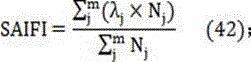
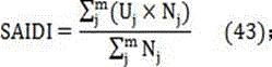
根据得到的负荷点可靠性指标,并结合基础数据中负荷点接入用 户数Nj,可计算系统的可靠性指标如下:According to the obtained reliability index of the load point, combined with the number of users N j connected to the load point in the basic data, the reliability index of the system can be calculated as follows:
平均系统停电频率指标SAIFI为:The average system outage frequency index SAIFI is:

平均系统停电持续时间指标SAIDI为:The average system outage duration indicator SAIDI is:

平均供电可用率指标ASAI-为:The average power supply availability index ASAI- is:

本发明采用上述技术方案,本发明有如下显著效果:The present invention adopts the above-mentioned technical scheme, and the present invention has the following remarkable effects:
本发明通过综合考虑当前配电网的不同自动化功能配置,划分为 非自动化模式、自动定位模式、自动隔离模式和自动转供模式四种功 能模式。对线路在不同自动化功能模式下的供电可靠性进行量化分析, 给出考虑故障停电的可靠性指标。通过计算可以得到配电网规划及改 造效果的量化结果,找出网络中依旧存在的薄弱环节,对提高供电可 靠性、指导配电网的建设和规划具有重要意义。The present invention is divided into four functional modes: non-automatic mode, automatic positioning mode, automatic isolation mode and automatic transfer mode by comprehensively considering different automatic function configurations of the current distribution network. The power supply reliability of the line under different automation function modes is quantitatively analyzed, and the reliability index considering the failure and power outage is given. Through the calculation, the quantitative results of the distribution network planning and transformation effect can be obtained, and the weak links that still exist in the network can be found out, which is of great significance for improving the reliability of power supply and guiding the construction and planning of the distribution network.
附图说明Description of drawings
图1是本发明的流程图。Figure 1 is a flow chart of the present invention.
图2是本发明的主馈线隔离区划分图。FIG. 2 is a division diagram of the main feeder isolation area of the present invention.
图3是本发明的分支线隔离区划分图。FIG. 3 is a division diagram of the branch line isolation area of the present invention.
图4是本发明的配网典型结构图。Fig. 4 is a typical structure diagram of the distribution network of the present invention.
具体实施方式Detailed ways
为使本发明的目的、技术方案及优点更加清楚明白,以下参照附 图并举出优选实施例,对本发明进一步详细说明。然而,需要说明的 是,说明书中列出的许多细节仅仅是为了使读者对本发明的一个或多 个方面有一个透彻的理解,即便没有这些特定的细节也可以实现本发 明的这些方面。In order to make the purpose, technical solutions and advantages of the present invention more clearly understood, the present invention will be described in further detail below with reference to the accompanying drawings and citing preferred embodiments. It is to be understood, however, that many of the details set forth in the specification are merely provided to provide the reader with a thorough understanding of one or more aspects of the invention, which may be practiced without these specific details.
一种考虑多功能配电自动化的配电网供电可靠性计算方法,如图 1所示,包括如下步骤,A method for calculating the reliability of distribution network power supply considering multi-function distribution automation, as shown in Figure 1, includes the following steps:
步骤1:根据给定的目标配电网的开关类型判断所配置的自动化 功能模式。配电自动化对配电网可靠性的影响主要表现在故障查找隔 离和转供电的实施速度,而故障隔离和恢复供电通过操作开关装置来 完成。Step 1: Determine the configured automation function mode according to the switch type of the given target distribution network. The influence of distribution automation on the reliability of distribution network is mainly reflected in the implementation speed of fault finding isolation and power transfer, and fault isolation and power restoration are completed by operating switchgear.
开关类型包括A类开关、B类开关、C类开关和D类开关,A类开 关对应自动转供模式具有最短的定位隔离时间和转供时间;B类开关 对应自动隔离模式具有较短的定位隔离时间和转供时间;C类开关对 应自动定位模式具有较长的定位隔离时间和转供时间;D类开关对应 非自动化模式具有最长的定位隔离时间和转供时间。自动化功能模式 包括非自动化模式、自动定位模式、自动隔离模式和自动转供模式。Switch types include A-type switches, B-type switches, C-type switches and D-type switches. A-type switches correspond to automatic transfer mode with the shortest positioning isolation time and transfer time; B-type switches correspond to automatic isolation mode with shorter positioning Isolation time and transfer time; C-type switch corresponding to automatic positioning mode has longer positioning isolation time and transfer time; D-type switch corresponding to non-automatic mode has the longest positioning isolation time and transfer time. The automatic function mode includes non-automatic mode, automatic positioning mode, automatic isolation mode and automatic transfer mode.
步骤2:根据确定的自动化功能模式计算主馈线元件故障下的负 荷点可靠性计算所采用的参数。具体过程为:Step 2: Calculate the parameters used in the reliability calculation of the load point under the failure of the main feeder element according to the determined automatic function mode. The specific process is:
步骤2.1:根据步骤1中给定的开关类型划分隔离区。隔离区以 开关为边界进行划分,开关间的元件集合为一个区域,相邻开关间的 区域称为最小隔离区,通过A类开关进行隔离的区域称为A类隔离区, 通过B类开关进行隔离的区域称为B类隔离区,通过C类开关进行的 区域称为C类隔离区,通过D类开关进行隔离的区域称为D类隔离区。Step 2.1: Divide the isolation area according to the switch type given in step 1. The isolation area is divided by the switch as the boundary. The components between the switches are grouped into one area. The area between adjacent switches is called the minimum isolation area. The isolated area is called a Class B isolation area, the area through a Class C switch is called a Class C isolation area, and the area isolated by a Class D switch is called a Class D isolation area.
步骤2.2:主馈线元件i发生故障时,根据步骤2.1中划分的隔 离区,以自动化等级为依据,由A至D搜索隔离区,直至搜索到故障 元件i所在的最小隔离区,不同类型隔离区的负荷点j进行可靠性计 算采用对应故障元件的故障率λj,i和故障停运时间rj,i。Step 2.2: When the main feeder element i fails, according to the isolation area divided in step 2.1, based on the automation level, search the isolation area from A to D until the smallest isolation area where the faulty component i is located, different types of isolation areas are searched. The reliability calculation of the load point j is carried out using the failure rate λ j,i of the corresponding faulty element and the failure downtime time r j,i .
搜索过程为:The search process is:
若线路配置A类开关且故障位于A类隔离区内,则A类隔离区上 游负荷点集合JA1对应的故障率、故障停运时间分别取故障元件i的 故障率λi、自动转供模式下的故障定位隔离时间rA;A类隔离区下游 负荷点集合JA2对应的故障率、故障停运时间分别取故障元件i的故 障率λi、自动转供模式下的转供时间rtA,公式如下:If the line is equipped with a class A switch and the fault is located in the class A isolation area, the failure rate and the fault outage time corresponding to the set of upstream load points J A1 in the class A isolation area are taken as the failure rate λ i of the faulty element i, and the automatic transfer mode The fault location isolation time r A under the A-class isolation zone downstream load point set J A2 corresponds to the failure rate and the fault outage time respectively take the failure rate λ i of the faulty element i, and the transfer time r tA in the automatic transfer mode , the formula is as follows:
λj,i=λi,j∈JA1 (1)λ j,i =λ i ,j∈J A1 (1)
rj,i=rA,j∈JA1 (2)r j,i =r A ,j∈J A1 (2)
λj,i=λi,j∈JA2 (3)λ j,i =λ i ,j∈J A2 (3)
rj,i=rtA,j∈JA2 (4)。r j,i =r tA ,j∈J A2 (4).
若线路配置B类开关且故障位于B类隔离区内,则B类隔离区上 游负荷点集合JB1对应的故障率、故障停运时间分别取故障元件i的 故障率λi、自动隔离模式下的故障定位隔离时间rB;B类隔离区下游 负荷点集合JB2对应的故障率、故障停运时间分别取故障元件i的故 障率λi、自动隔离模式下的转供时间rtB,公式如下:If the line is equipped with a class B switch and the fault is located in the class B isolation area, the failure rate and the fault outage time corresponding to the set of upstream load points J B1 in the class B isolation area are taken as the failure rate λ i of the faulty element i, and in the automatic isolation mode The fault location isolation time r B ; the fault rate and the fault outage time corresponding to the downstream load point set J B2 of the class B isolation area respectively take the fault rate λ i of the faulty element i and the transfer time r tB in the automatic isolation mode, the formula as follows:
λj,i=λi,j∈JB1 (5)λ j,i =λ i ,j∈J B1 (5)
rj,i=rB,j∈JB1 (6)r j,i =r B ,j∈J B1 (6)
λj,i=λi,j∈JB2 (7)λ j,i =λ i ,j∈J B2 (7)
rj,i=rtB,j∈JB2 (8)。r j,i =r tB ,j∈J B2 (8).
若线路配置C类开关且故障位于C类隔离区内,C类隔离区上游 首遇开关至其上游首遇自动化等级更高的开关(若无自动化等级更高 的开关则取线路首端开关)间的区域内负荷点集合为JC1,该负荷点 集合对应的故障率、故障停运时间分别取故障元件i的故障率λi、自 动定位模式下的故障定位隔离时间rC;C类隔离区下游首遇开关至其 下游首遇自动化等级更高的开关(若无自动化等级更高的开关则取线 路末端开关)间的区域内负荷点集合为JC2,该负荷点集合对应的故 障率、故障停运时间分别取故障元件i的故障率λi、自动定位模式下 的转供时间rtC,公式如下:If the line is equipped with a class C switch and the fault is located in the class C isolation area, the upstream first encounter switch in the class C isolation area to the upstream first encounter switch with a higher automation level (if there is no switch with a higher automation level, the line head switch is used) The set of load points in the area between the two is J C1 , and the corresponding failure rate and fault outage time of the load point set are the failure rate λ i of the faulty element i and the fault location isolation time r C in the automatic location mode; Class C isolation The set of load points in the area between the first encounter switch in the downstream of the zone and the first encounter switch with a higher automation level downstream (if there is no switch with a higher automation level, take the switch at the end of the line) is J C2 , and the failure rate corresponding to the load point set , and the failure outage time respectively take the failure rate λ i of the faulty component i and the transfer time r tC in the automatic positioning mode, the formulas are as follows:
λj,i=λi,j∈JC1 (9)λ j,i =λ i ,j∈J C1 (9)
rj,i=rC,j∈JC1 (10)r j,i =r C ,j∈J C1 (10)
λj,i=λi,j∈JC2 (11)λ j,i =λ i ,j∈J C2 (11)
rj,i=rtC,j∈JC2 (12)。r j,i =r tC ,j∈J C2 (12).
若线路配置D类开关且故障位于D类隔离区内,D类隔离区上游 首遇开关至其上游首遇自动化等级更高的开关(若无自动化等级更高 的开关则取线路首端开关)间的区域内负荷点集合为JD1,该负荷点 集合对应的故障率、故障停运时间分别取故障元件i的故障率λi、无 自动化模式下的故障定位隔离时间rD;D类隔离区下游首遇开关至其 下游首遇自动化等级更高的开关(若无自动化等级更高的开关则取线 路首端开关)间的区域内负荷点集合为JD2,该负荷点集合对应的故 障率、故障停运时间分别取故障元件i的故障率λi、无自动化模式下 的转供时间rtD,公式如下:If the line is equipped with a class D switch and the fault is located in the class D isolation area, the upstream first encounter switch of the D class isolation area will be the first encounter switch with a higher automation level upstream (if there is no switch with a higher automation level, the line head switch will be used) The set of load points in the area between the two points is J D1 , and the corresponding failure rate and fault outage time of the load point set are the failure rate λ i of the faulty element i and the fault location isolation time r D in the non-automatic mode; Class D isolation The set of load points in the area between the first encounter switch in the downstream of the zone and the first encounter switch with a higher automation level downstream (if there is no switch with a higher automation level, take the switch at the head end of the line) is J D2 , and the fault corresponding to this load point set Take the failure rate λ i of the faulty component i and the transfer time r tD in the non-automatic mode respectively, the formula is as follows:
λj,i=λi,j∈JD1 (13)λ j,i =λ i ,j∈J D1 (13)
rj,i=rD,j∈JD1 (14)r j,i =r D ,j∈J D1 (14)
λj,i=λi,j∈JD2 (15)λ j,i =λ i ,j∈J D2 (15)
rj,i=rtD,j∈JD2 (16)。r j,i =r tD ,j∈J D2 (16).
由A至D不断缩小隔离区范围,最后可搜索至故障元件i所在的 最小隔离区,该隔离区中的负荷点集合为Jf,则这些负荷点在该元件 故障时对应的故障率、故障停运时间分别取故障元件i的故障率λi、 元件修复时间ri,公式如下:From A to D, the scope of the isolation area is continuously narrowed, and finally the smallest isolation area where the faulty component i is located can be searched. The set of load points in the isolation area is J f , then the corresponding failure rate and failure rate of these load points when the component fails The outage time is taken as the failure rate λ i of the faulty component i and the component repair time r i respectively, and the formula is as follows:
λj,i=λi,j∈Jf (17)λ j,i =λ i ,j∈J f (17)
rj,i=ri,j∈Jf (18)。r j,i =r i ,j∈J f (18).
步骤3:根据确定的自动化功能模式确定分支线元件故障下的 负荷点可靠性计算所采用的参数。具体过程为:Step 3: Determine the parameters used in the reliability calculation of the load point under the fault of the branch line element according to the determined automatic function mode. The specific process is:
步骤3.1:对于系统分支线元件i故障,当故障元件上游首遇D 类开关、首遇C类开关和首遇B类开关时,分别将分支线划分为D类 分支隔离区、C类分支隔离区和B类分支隔离区;Step 3.1: For the fault of the system branch line component i, when the upstream of the faulty component encounters the first class D switch, the first class C switch and the first class B switch, the branch line is divided into the class D branch isolation area and the class C branch isolation area respectively. Zone and Category B Branch Quarantine;
步骤3.2:根据步骤3.1中划分的分支隔离区,以故障元件所在 最小隔离区为起点进行隔离区搜索,对不同类型隔离区的负荷点j进 行可靠性计算采用对应故障元件的故障率λ'j,i和故障停运时间r'j,i。Step 3.2: According to the branch isolation area divided in step 3.1, the isolation area is searched starting from the minimum isolation area where the faulty element is located, and the reliability of load points j of different types of isolation areas is calculated. The failure rate λ'j of the corresponding faulty element is used. ,i and the downtime r' j,i .
3.2的具体过程为:3.2 The specific process is:
故障元件i所在最小隔离区及其下游区域内负荷点集合J'f的可 靠性计算参数取分支线故障元件i的故障率λ'i和该元件修复时间r'i, 公式如下The reliability calculation parameters of the load point set J' f in the minimum isolation area where the faulty element i is located and its downstream area are taken as the failure rate λ' i of the branch line fault element i and the repair time r' i of the element, the formula is as follows
λ'j,i=λ'i,j∈J'f(19)λ' j,i =λ' i ,j∈J' f (19)
r'j,i=r'i,j∈J'f(20);r' j, i =r' i ,j∈J' f (20);
对于D类分支隔离区,其上游首遇开关至其上游首遇自动化等级 更高的开关间区域负荷点集合J'D1的可靠性计算所用参数取分支线故 障元件i的故障率λ'i、无自动化模式下的故障定位隔离时间r'D,公式 如下:For the Class D branch isolation area, the parameters used in the reliability calculation of the regional load point set J' D1 between the upstream first encounter switch to the upstream first encounter switch with a higher automation level are the failure rate λ' i of the branch line fault element i, The fault location isolation time r' D without automation mode, the formula is as follows:
λ'j,i=λ'i,j∈J'D1 (21)λ' j,i =λ' i ,j∈J' D1 (21)
r'j,i=r'D,j∈J'D1 (22)。r' j,i =r' D ,j∈J' D1 (22).
对于C类分支隔离区,其上游首遇开关至其上游首遇自动化等级 更高的开关间区域负荷点集合J'C1的可靠性计算参数取分支线故障元 件i的故障率λ'i、自动定位模式下的故障定位隔离时间r'C,公式如下:For the Class C branch isolation area, the reliability calculation parameters of the load point set J' C1 between the upstream first encounter switch to the upstream first encounter switch with a higher automation level are taken as the failure rate λ' i of the branch line fault element i, the automatic The fault location isolation time r' C in the location mode, the formula is as follows:
λ'j,i=λ'i,j∈J'C1 (23)λ' j,i =λ' i ,j∈J' C1 (23)
r‘j,i=r’C,j∈J'C1 (24)。r' j,i =r' C ,j∈J' C1 (24).
对于B类分支隔离区,B类分支隔离区外的负荷点集合J'B1的可 靠性计算参数取分支线故障元件i的故障率λ'i、自动隔离模式下的故 障定位隔离时间r'B,公式如下:For the B-type branch isolation area, the reliability calculation parameters of the load point set J' B1 outside the B-type branch isolation area are the failure rate λ' i of the branch line fault element i, and the fault location isolation time r' B in the automatic isolation mode , the formula is as follows:
λ'j,i=λ'i,j∈J'B1 (25)λ' j,i =λ' i ,j∈J' B1 (25)
r'j,i=r'B,j∈J'B1 (26)。r' j,i =r' B ,j∈J' B1 (26).
若分支线上游无B类开关,则该分支线元件故障会导致该支线所 接入的主馈线段停电;且If there is no class B switch upstream of a branch line, the failure of the branch line element will cause the main feeder segment to which the branch line is connected to lose power; and
1)主馈线若有A类隔离区,则A类隔离区外负荷点集合可靠性 参数取值为:A类隔离区上游负荷点集合J'A1取分支线故障元件i的故 障率λ'i、自动转供模式下的故障定位隔离时间r'A;A类隔离区下游负 荷点集合J'A2取分支线故障元件i的故障率λ'i、自动转供模式下的转 供时间r'tA,公式如下:1) If the main feeder has a Class A isolation area, the reliability parameter of the load point set outside the Class A isolation area is as follows: The upstream load point set J' A1 of the Class A isolation area takes the failure rate λ' i of the branch line fault element i , the fault location isolation time r' A in the automatic transfer mode; the set J' A2 of the downstream load points in the class A isolation area takes the failure rate λ' i of the branch line fault element i, and the transfer time r' in the automatic transfer mode tA , the formula is as follows:
λ'j,i=λ'i,j∈J'A1 (27)λ' j,i =λ' i ,j∈J' A1 (27)
r'j,i=r'A,j∈J'A1 (28)r' j,i =r' A ,j∈J' A1 (28)
λ'j,i=λ'i,j∈J'A2 (29)λ' j,i =λ' i ,j∈J' A2 (29)
r'j,i=r'tA,j∈J'A2 (30)。r' j,i =r' tA ,j∈J' A2 (30).
2)主馈线若有B类隔离区,则B类隔离区外负荷点集合可靠性 参数取值为:B类隔离区上游负荷点集合J'B1取分支线故障元件i的故 障率λ'i、自动隔离模式下的故障定位隔离时间r'B;B类隔离区下游负 荷点集合J'B2取分支线故障元件i的故障率λ'i、自动转供模式下的转 供时间r'tB,公式如下:2) If the main feeder has a Class B isolation area, the reliability parameter of the load point set outside the Class B isolation area is as follows: the upstream load point set J' B1 of the Class B isolation area takes the failure rate λ' i of the branch line fault element i , the fault location and isolation time r' B in the automatic isolation mode; the set of load points J' B2 downstream of the class B isolation area takes the failure rate λ' i of the faulty component i of the branch line, and the transfer time r' tB in the automatic transfer mode , the formula is as follows:
λ'j,i=λ'i,j∈J'B1 (31)λ' j,i =λ' i ,j∈J' B1 (31)
r'j,i=r'B,j∈J'B1 (32);r' j,i =r' B ,j∈J' B1 (32);
λ'j,i=λ'i,j∈J'B2 (33)λ' j,i =λ' i ,j∈J' B2 (33)
r'j,i=r'tB,j∈J'B2 (34);r' j,i =r' tB , j∈J'B2 (34);
对于A、B类隔离区中还未取值的负荷点集合J'rest,For the load point set J' rest that has not yet taken a value in Class A and Class B isolation areas,
1)若所在分支线上有C类开关,则未取值负荷点集合的可靠性 计算参数取分支线故障元件i的故障率λ'i、自动定位模式下的故障定 位隔离时间r’C,公式如下:1) If there is a class C switch on the branch line, the reliability calculation parameter of the load point set with no value is the failure rate λ' i of the fault element i of the branch line, and the fault location isolation time r' C in the automatic location mode, The formula is as follows:
λ'j,i=λ'i,j∈J'rest (35)λ' j,i =λ' i ,j∈J' rest (35)
r‘j,i=r’C,j∈J'rest (36)。r' j,i =r' C , j∈J'rest (36).
2)若所在分支线上仅有D类开关,则未取值负荷点集合的可靠 性计算参数取分支线故障元件i的故障率λ'i、无自动化模式下的故障 定位隔离时间r'D,公式如下:2) If there is only a D-type switch on the branch line, the reliability calculation parameter of the load point set with no value is the failure rate λ' i of the fault element i of the branch line, and the fault location and isolation time r' D in the non-automatic mode , the formula is as follows:
λ'j,i=λ'i,j∈J'rest (37)λ' j,i =λ' i ,j∈J' rest (37)
r'j,i=r'D,j∈J'rest (38)。r' j,i =r' D , j∈J'rest (38).
步骤4:根据步骤2和步骤3中的可靠性参数进行计算目标配电 网的可靠性指标。Step 4: Calculate the reliability index of the target distribution network according to the reliability parameters in
计算可靠性指标的具体过程为:The specific process of calculating the reliability index is as follows:
对系统元件数为n、负荷点数为m的目标网架,对每一个元件进 行故障假设,重复进行步骤2或步骤3,确定每一个元件故障情况下, 各负荷点可靠性计算的基本参数。For the target grid with n system components and m load points, make fault assumptions for each component, repeat
定义负荷点j的可靠性参数为停电率λj,每次故障停电时间rj和 年平均停电时间Uj,其中j=1,K,i,K m。The reliability parameters that define load point j are power outage rate λ j , outage time r j for each fault and annual average outage time U j , where j=1, K, i, K m.
λj等于每个系统元件故障对该点故障率产生影响的叠加,公式如 下, λj is equal to the superposition of the influence of each system component failure on the failure rate at that point, and the formula is as follows,

rj等于每个系统元件故障对该点停电时间产生影响的叠加,公式 如下,r j is equal to the superposition of the influence of each system component failure on the outage time at that point, and the formula is as follows,

年平均停电时间Uj公式如下,The formula for the average annual power outage time U j is as follows:

根据得到的负荷点可靠性指标,并结合基础数据中负荷点接入用 户数Nj,可计算系统的可靠性指标如下:According to the obtained reliability index of the load point and combined with the number of users N j connected to the load point in the basic data, the reliability index of the system can be calculated as follows:
平均系统停电频率指标SAIFI为:The average system outage frequency index SAIFI is:

平均系统停电持续时间指标SAIDI为:The average system outage duration indicator SAIDI is:

平均供电可用率指标ASAI为:The average power supply availability index ASAI is:

以上所述仅是本发明的优选实施方式,应当指出,对于本技术领 域的普通技术人员来说,在不脱离本发明原理的前提下,还可以作出 若干改进和润饰,这些改进和润饰也应视为本发明的保护范围。The above are only the preferred embodiments of the present invention. It should be pointed out that for those skilled in the art, without departing from the principles of the present invention, several improvements and modifications can be made, and these improvements and modifications should also be It is regarded as the protection scope of the present invention.
Claims (1)




Priority Applications (1)
| Application Number | Priority Date | Filing Date | Title |
|---|---|---|---|
| CN201810213253.5A CN108564252B (en) | 2018-03-15 | 2018-03-15 | A Reliability Calculation Method of Distribution Network Power Supply Considering Multifunctional Distribution Automation |
Applications Claiming Priority (1)
| Application Number | Priority Date | Filing Date | Title |
|---|---|---|---|
| CN201810213253.5A CN108564252B (en) | 2018-03-15 | 2018-03-15 | A Reliability Calculation Method of Distribution Network Power Supply Considering Multifunctional Distribution Automation |
Publications (2)
| Publication Number | Publication Date |
|---|---|
| CN108564252A CN108564252A (en) | 2018-09-21 |
| CN108564252B true CN108564252B (en) | 2022-05-10 |
Family
ID=63532675
Family Applications (1)
| Application Number | Title | Priority Date | Filing Date |
|---|---|---|---|
| CN201810213253.5A Active CN108564252B (en) | 2018-03-15 | 2018-03-15 | A Reliability Calculation Method of Distribution Network Power Supply Considering Multifunctional Distribution Automation |
Country Status (1)
| Country | Link |
|---|---|
| CN (1) | CN108564252B (en) |
Families Citing this family (2)
| Publication number | Priority date | Publication date | Assignee | Title |
|---|---|---|---|---|
| CN110738411B (en) * | 2019-10-12 | 2023-05-05 | 上海电力大学 | Reliability analysis method for typical wiring mode of power distribution network |
| CN113779902B (en) * | 2021-09-09 | 2024-06-14 | 广东电网有限责任公司 | A method, device, equipment and storage medium for determining line reliability |
Citations (1)
| Publication number | Priority date | Publication date | Assignee | Title |
|---|---|---|---|---|
| CN104462767A (en) * | 2014-11-05 | 2015-03-25 | 广东电网有限责任公司江门供电局 | Rapid power distribution network reliability assessment method based on element transfer characteristics |
Family Cites Families (2)
| Publication number | Priority date | Publication date | Assignee | Title |
|---|---|---|---|---|
| WO2009076410A1 (en) * | 2007-12-12 | 2009-06-18 | Abb Research Ltd. | Load restoration for feeder automation in electric power distribution systems |
| CN105406470B (en) * | 2015-12-21 | 2017-12-12 | 国家电网公司 | A kind of reliability of active power distribution network method based on switching boundary subregion |
-
2018
- 2018-03-15 CN CN201810213253.5A patent/CN108564252B/en active Active
Patent Citations (1)
| Publication number | Priority date | Publication date | Assignee | Title |
|---|---|---|---|---|
| CN104462767A (en) * | 2014-11-05 | 2015-03-25 | 广东电网有限责任公司江门供电局 | Rapid power distribution network reliability assessment method based on element transfer characteristics |
Non-Patent Citations (2)
| Title |
|---|
| 考虑多模式配电自动化特征的配电网可靠性评估方法;曾强;《电力系统及其自动化学报》;20170131;第128-134页 * |
| 计及集中式馈线自动化的配电网可靠性评估模型;商海涛;《电力自动化设备》;20170531;第129-135、141页 * |
Also Published As
| Publication number | Publication date |
|---|---|
| CN108564252A (en) | 2018-09-21 |
Similar Documents
| Publication | Publication Date | Title |
|---|---|---|
| KR102763685B1 (en) | System for identifying fault section of power distribution system | |
| CN109274095A (en) | Method and system for user topology estimation of low voltage distribution network based on mutual information | |
| CN109586281B (en) | Power distribution network reliability assessment method, device and medium based on node optimization number | |
| CN106327033B (en) | A method for analyzing cascading faults in power systems based on Markov processes | |
| CN113793039B (en) | A Reliability Assessment Method for Medium and Low Voltage Distribution Networks Considering Multiple Types of Terminals | |
| CN105406470A (en) | Reliability evaluation method for active power distribution network based on switch boundary subarea division | |
| CN106570779A (en) | Method and system for reliability analysis of DC distribution network | |
| CN115825656B (en) | Fault monitoring method, device and system for power distribution network of new energy photovoltaic power station | |
| CN103824234B (en) | Blocking and hierarchical structure based power distribution system reliability evaluation method | |
| CN105656036B (en) | Consider trend and the probability static security analysis method of sensitivity uniformity equivalence | |
| CN103457249A (en) | Smart distribution network distributed type pilot protection method and system | |
| CN114720820A (en) | Power distribution network feeder fault positioning method and device, terminal equipment and storage medium | |
| CN105046011B (en) | The electrical device status rapid analysis method calculated based on distributed electrical net topology | |
| CN104215879A (en) | Method and system for locating short-circuit faults of power distribution networks | |
| CN104765933A (en) | Method for implementing intelligent layering of wiring diagram of distribution area | |
| CN107681652A (en) | A kind of feeder line N 1 for considering distributed power source can fill calculation of capacity model | |
| CN109038554B (en) | A method for generating local topology of intelligent power distribution terminal | |
| CN109064026B (en) | A method for evaluating the immune time of industrial process parameters considering the operation mode of the power supply system | |
| CN108564252A (en) | A kind of distribution network reliability computational methods considering multifunctional ligand electric automation | |
| CN113675877B (en) | Deep learning-based distributed power supply distribution network fault diagnosis method | |
| CN111090021B (en) | Fault positioning method for composite low-voltage power distribution network | |
| CN111157851B (en) | A kind of distribution network fault location method and system | |
| CN105977932B (en) | A kind of online computing system of power distribution network locality protection associated domain and its method | |
| CN104218668B (en) | The tracking defining method of the prepared auto restart of action is caused during device fails | |
| CN103441480B (en) | A kind of Novel traveling-wave protection method of wide-area power grid |
Legal Events
| Date | Code | Title | Description |
|---|---|---|---|
| PB01 | Publication | ||
| PB01 | Publication | ||
| SE01 | Entry into force of request for substantive examination | ||
| SE01 | Entry into force of request for substantive examination | ||
| GR01 | Patent grant | ||
| GR01 | Patent grant |