Method and device for implementing a controlled retarder brake of a vehicle
Technical Field
The present invention relates to vehicle braking technology, and more particularly, to a method for implementing vehicle braking, an apparatus implementing the method, and a computer storage medium implementing the method.
Background
In order to ensure driving safety, the vehicle is generally required to be equipped with a set of secondary braking systems. On vehicles where electronic parking brakes (APBs) replace the traditional mechanical handbrake or cable, the function of the secondary braking system is performed by a controlled retard brake (CDP) module. CDP is an accessory function of the automotive electronics function of an Electronic Stability Program (ESP) device that can slow the vehicle to a standstill in a manner requested by the driver. For a vehicle equipped with an APB system, the CDP function of the ESP is activated when the driver issues an emergency brake command by pulling the APB button. On the other hand, when the driver releases the APB button, the CDP function will go to sleep.
However, existing CDP functionality has a number of technical disadvantages. For example, in an ESP device, CDP components are limited by mechanical performance, have a very short operating life (typically only a cumulative service time of ten minutes or more than 100 activations), and therefore require frequent maintenance over the life cycle of the vehicle. In addition, in order to ensure that the CDP component is in a usable state, a warning device is required to be arranged to remind a user in time when the CDP component is in an overdue service condition, so that potential safety hazards are avoided.
From the foregoing, it can be seen that a CDP function implementation that overcomes the various disadvantages described above is desirable.
Disclosure of Invention
It is an object of the present invention to provide a method for implementing controlled service retarding braking of a vehicle which avoids frequent maintenance of CDP components and has the advantage of simplicity of implementation.
A method for implementing controlled retard braking of a vehicle according to one aspect of the present invention comprises the steps of:
in response to a braking request from a brake park brake system and when a controlled retard braking function of an electromechanical brake booster is available, an electronic stability program issues a braking command to the electromechanical brake booster;
in response to a braking command, the electromechanical brake booster generates a driving signal according to the opening degree of the pulled-up control button of the automatic parking brake system, the pulling-up duration and a set parking brake force curve; and
the drive signal is used to drive the electric motor of the electromechanical brake booster to produce the desired pressure in the brake master cylinder to effect a controlled deceleration of the vehicle.
Preferably, in the above method, if the controlled retard braking function of the electromechanical brake booster is not available, the controlled retard braking of the vehicle is implemented using a controlled retard braking module of an electronic stability program device.
It is another object of the present invention to provide a device for effecting controlled service braking of a vehicle which avoids frequent maintenance of the CDP components and has the advantage of simplicity of implementation.
An apparatus for implementing a controlled retard brake for a vehicle according to one aspect of the present invention includes an electronic stability program, an automatic parking brake system, and an electromechanical brake booster including a controller, a motor, and a booster piston, wherein the electronic stability program is configured to issue a brake command to the controller if a controlled retard brake function of the electromechanical brake booster is determined to be available upon receipt of a brake request from a brake parking brake system, the controller configured to perform the steps of: in response to a braking instruction, generating a driving signal according to the opening degree of the pulled-up control button of the automatic parking braking system, the pulling-up duration and a set parking braking force curve; and
the motor is driven with the drive signal such that the motor pushes the booster piston in cooperation with an input rod coupled to the pedal to generate a desired pressure in the brake master cylinder, thereby achieving a controlled deceleration of the vehicle.
Preferably, in the above apparatus, the electronic stability program means is further configured to implement the controlled retard braking of the vehicle with the controlled retard braking module of the electronic stability program means if it is determined that the controlled retard braking function of the electromechanical brake booster is not available.
Preferably, in the above apparatus, further comprising a gear transmission unit coupling the force output from the motor to the booster piston.
Preferably, in the above apparatus, the power and control unit and the automatic parking brake system communicate via an in-vehicle network.
It is another object of the present invention to provide an electronic stability programmer that avoids frequent maintenance of CDP components and has the advantage of ease of implementation.
An electronic stability program according to one aspect of the present invention is configured to perform the steps of:
determining whether a controlled retard braking function of the electromechanical brake booster is available upon receiving a braking request from the brake park brake system;
if the controlled retard braking function of the electromechanical brake booster is available, a braking command is issued to the electromechanical brake booster to implement the controlled retard braking function with the electromechanical brake booster.
The present invention also provides a computer-readable storage medium on which a computer program is stored which, when executed by a processor, performs the steps of:
determining whether a controlled retard braking function of the electromechanical brake booster is available upon receiving a braking request from the brake park brake system;
if the controlled retard braking function of the electromechanical brake booster is available, a braking command is issued to the electromechanical brake booster to implement the controlled retard braking function with the electromechanical brake booster.
According to the invention, the braking force is derived from the pressure of the brake master cylinder, which is achieved without the use of mechanical components as in an ESP, thus greatly reducing the need for maintenance of the CDP function. In addition, the controlled deceleration process can be realized by utilizing the existing electromechanical brake booster, so the method has the advantages of simple implementation, obvious improvement on the braking performance and the like. Furthermore, in the preferred embodiment of the present invention, the controlled deceleration function of the electromechanical brake booster is a backup to the CDP function in the ESP system, thereby greatly improving reliability.
Drawings
The above and/or other aspects and advantages of the present invention will become more apparent and more readily appreciated from the following description of the various aspects taken in conjunction with the accompanying drawings, in which like or similar elements are designated with like reference numerals. The drawings comprise:
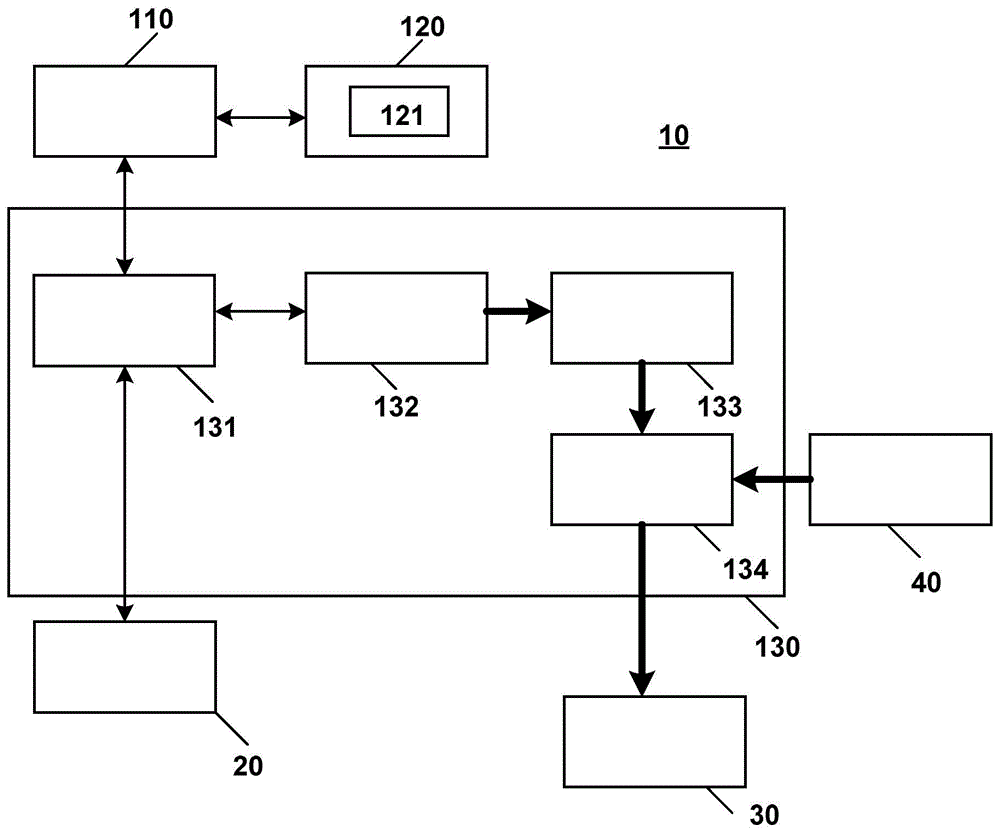
fig. 1 is a block diagram of an apparatus for effecting controlled deceleration during vehicle braking in accordance with one embodiment of the present invention.
FIG. 2 is a flow chart of a method for achieving controlled deceleration during vehicle braking in accordance with another embodiment of the present invention.
Detailed Description
The present invention will now be described more fully hereinafter with reference to the accompanying drawings, in which exemplary embodiments of the invention are shown. This invention may, however, be embodied in different forms and should not be construed as limited to the embodiments set forth herein. The embodiments described above are intended to provide a full and complete disclosure of the present invention to more fully convey the scope of the invention to those skilled in the art.
Fig. 1 is a block diagram of an apparatus for implementing controlled retard braking of a vehicle in accordance with one embodiment of the present invention.
As shown in fig. 1, the device 10 for implementing a controlled retard brake for a vehicle includes an automatic parking brake module 110, an Electronic Stability Program (ESP) device 120, and an electromechanical brake booster 130. In the embodiment shown in fig. 1, the controlled deceleration function of the vehicle may be implemented by one of a Controlled Deceleration (CDP) module 121 or an electromechanical brake booster 130 in an Electronic Stability Program (ESP) 120. Preferably, the electromechanical brake booster 130 is preferred, with the CDP module in the ESP 120 acting as a redundant backup.
Referring to FIG. 1, the electromechanical brake booster 130 includes a controller 131, a motor 132, a gear assembly 133, and a booster piston 134. In the present embodiment, the controller 131 is configured to generate a drive signal for the motor 132 and output the drive signal to the motor 132, the motor 132 being coupled to the booster piston 134 via the gear transmission member 133.
As shown in fig. 1, the pedal stroke sensor 20 is configured to measure a tread force and a tread speed of the pedal. The controller 131 receives a measurement signal of the pedal stroke sensor 20. When a controlled retard braking request is issued by the driver through the automatic parking brake system 110, the electronic stability program means 120 converts the request into a braking command, and the controller 131 is configured to generate a driving signal for driving the motor 132 according to the opening degree at which the automatic parking brake system control button is pulled up, the duration of the pull-up, and a set braking pattern or parking brake force profile in response to the braking command from the electronic stability program means 120 of the vehicle. The brake mode described herein may be, for example, a brake effect or a brake response sensitivity (i.e., a correspondence relationship between the opening degree, duration, and brake force at which the driver pulls up the automatic parking brake module control button). The braking effect or braking response sensitivity is different for the same vehicle in different braking modes.
In the embodiment shown in fig. 1, the ESP 120 communicates with the automatic parking brake module 110 to monitor signals of target deceleration, deceleration request, master cylinder pressure, and wheel speed of the vehicle, on the one hand, and the ESP 120 communicates with the electromechanical brake booster 130 to monitor CDP functional status signals of the electromechanical brake booster 130, on the other hand. When the CDP trigger condition is met and the CDP function status signal returned by the electromechanical brake booster 130 indicates that the CDP function is fully functional, the ESP 120 determines that the braking operation of the vehicle is to be completed by the electromechanical brake booster 130. Thus, ESP 120 will generate a CDP drive signal for electromechanical brake booster 130 and trigger the CDP function of electromechanical brake booster 130.
In the embodiment shown in fig. 1, the motor 132 will output power, driven by the drive signal of the controller 131, which is transmitted to the booster piston 134 via the gear transmission member 133, thereby pushing the booster piston 134 to generate a desired pressure in the brake master cylinder 20, thereby achieving a controlled deceleration of the vehicle.
In the present embodiment, controller 131 preferably communicates with automatic parking brake system 110 and ESP 120 via the vehicle network (e.g., via a CAN bus).
Automatic parking brake system 110 may be communicatively coupled with electromechanical brake booster 130 and ESP 120, with the braking requests generated by it being received by controller 131 of electromechanical brake booster 130 and ESP 120 at the same time. On the other hand, the controller 131 may be configured to periodically send a signal indicative of the status of the CDP function (e.g., a CDP available signal indicating whether the CDP function is available, a CDP active signal indicating whether the CDP function is currently active, etc.) to the ESP 120, or send a signal indicative of the status of the CDP function to the ESP 120 in response to a braking command. If the signal of CDP function status sent by the controller 131 indicates that the CDP function is functioning properly, the ESP 120 determines that the braking operation of the vehicle is to be completed by the electromechanical brake booster 130, and if the signal of CDP function status sent indicates that the CDP function is malfunctioning or not functioning properly, the ESP 120 activates its own equipped CDP function module 121 to complete the braking operation of the vehicle. That is, in this embodiment, the electromechanical brake booster 130 is preferably selected to perform the CDP function, and the CDP module of the ESP 120 is used as a redundant backup.
FIG. 2 is a flow chart of a method for implementing controlled retard braking of a vehicle in accordance with another embodiment of the present invention. Illustratively, the brake parking brake system 110, the ESP 120, and the electromechanical brake booster 130 shown in fig. 1 are employed as the execution components of the various steps of the present embodiment. It will be understood by those skilled in the art that the implementation of the steps of the method of the present embodiment is not limited to physical devices having a specific structure.
As shown in fig. 2, at step 210, automatic parking brake system 110 sends a brake request to controller 131 of electromechanical brake booster 130 and ESP 120 simultaneously, or sends a brake request only to EPS 120.
Proceeding to step 220, ESP 120 determines whether to issue a braking command to controller 131 to perform the CDP function during vehicle braking based on the signal sent by controller 131 indicating the status of the CDP function. Specifically, if the CDP functional status signal indicates that the CDP function of the electromechanical brake booster 130 is normal or fully functional, step 230 is entered, for example, by issuing a braking command to the electromechanical brake booster 130 to perform the braking operation of the vehicle, otherwise step 240 is entered, wherein the CDP functional module in the ESP system performs the braking operation of the vehicle.
In step 230, the controller 131 generates a driving signal according to the opening degree of the automatic parking brake system control button being pulled up, the duration of the pulling up, and the set braking mode or parking braking force profile in response to the braking command.
Proceeding to step 250, the controller 131 drives the motor 132 with the drive signal such that the motor 132 pushes the booster piston 134 in cooperation with the input rod 40 to generate a desired pressure within the brake master cylinder 30 to achieve a controlled deceleration of the vehicle.
According to a further aspect of the invention, a computer-readable storage medium is also provided, on which a computer program is stored which, when being executed by a processor, is adapted to carry out the method described above with reference to fig. 2.
The embodiments and examples set forth herein are presented to best explain the embodiments in accordance with the present technology and its particular application and to thereby enable those skilled in the art to make and utilize the invention. However, those skilled in the art will recognize that the foregoing description and examples have been presented for the purpose of illustration and example only. The description as set forth is not intended to cover all aspects of the invention or to limit the invention to the precise form disclosed.