CN108802423B - Method for flow measurement through non-overhanging type micro-sound detector - Google Patents
Method for flow measurement through non-overhanging type micro-sound detector Download PDFInfo
- Publication number
- CN108802423B CN108802423B CN201810604669.XA CN201810604669A CN108802423B CN 108802423 B CN108802423 B CN 108802423B CN 201810604669 A CN201810604669 A CN 201810604669A CN 108802423 B CN108802423 B CN 108802423B
- Authority
- CN
- China
- Prior art keywords
- flow
- acoustic
- vortex
- detector
- velocity
- Prior art date
- Legal status (The legal status is an assumption and is not a legal conclusion. Google has not performed a legal analysis and makes no representation as to the accuracy of the status listed.)
- Active
Links
Images


Classifications
-
- G—PHYSICS
- G01—MEASURING; TESTING
- G01P—MEASURING LINEAR OR ANGULAR SPEED, ACCELERATION, DECELERATION, OR SHOCK; INDICATING PRESENCE, ABSENCE, OR DIRECTION, OF MOVEMENT
- G01P5/00—Measuring speed of fluids, e.g. of air stream; Measuring speed of bodies relative to fluids, e.g. of ship, of aircraft
- G01P5/24—Measuring speed of fluids, e.g. of air stream; Measuring speed of bodies relative to fluids, e.g. of ship, of aircraft by measuring the direct influence of the streaming fluid on the properties of a detecting acoustical wave
- G01P5/241—Measuring speed of fluids, e.g. of air stream; Measuring speed of bodies relative to fluids, e.g. of ship, of aircraft by measuring the direct influence of the streaming fluid on the properties of a detecting acoustical wave by using reflection of acoustical waves, i.e. Doppler-effect
- G01P5/244—Measuring speed of fluids, e.g. of air stream; Measuring speed of bodies relative to fluids, e.g. of ship, of aircraft by measuring the direct influence of the streaming fluid on the properties of a detecting acoustical wave by using reflection of acoustical waves, i.e. Doppler-effect involving pulsed waves
-
- G—PHYSICS
- G01—MEASURING; TESTING
- G01P—MEASURING LINEAR OR ANGULAR SPEED, ACCELERATION, DECELERATION, OR SHOCK; INDICATING PRESENCE, ABSENCE, OR DIRECTION, OF MOVEMENT
- G01P5/00—Measuring speed of fluids, e.g. of air stream; Measuring speed of bodies relative to fluids, e.g. of ship, of aircraft
- G01P5/01—Measuring speed of fluids, e.g. of air stream; Measuring speed of bodies relative to fluids, e.g. of ship, of aircraft by using swirlflowmeter
Landscapes
- Engineering & Computer Science (AREA)
- Physics & Mathematics (AREA)
- Aviation & Aerospace Engineering (AREA)
- General Physics & Mathematics (AREA)
- Acoustics & Sound (AREA)
- Multimedia (AREA)
- Measurement Of Mechanical Vibrations Or Ultrasonic Waves (AREA)
- Measuring Volume Flow (AREA)
- Indicating Or Recording The Presence, Absence, Or Direction Of Movement (AREA)
Abstract
本发明公开了一种通过非外伸式微缩声探测器进行流动测量的方法,属于流体力学领域。将各微型声探测器分别布置于被测风机内部,针对某个声探测器A,发出相位确定的一个声信号给流动边界层的某流动涡K并发生反射,得到A与涡K的i方向上的多普勒频移速度分量;同理,另一声探测器B得到涡k在j方向上的多普勒频移速度分量;将不同的速度分量叠加,得到涡K的速度大小和方向;各探测器以恒定的时间间隔发出脉冲声波信号,得到多个涡的对应方向上的多普勒频移分量;布置的若干声探测器呈线型或平面垂直,分别实现对流动边界层内部流动平面速度场和三维速度场的测量。本发明瞬时反应迅速优势且误差小,消耗的资源少,有很重要的推动意义。
The invention discloses a method for measuring flow through a non-extension type microscopic acoustic detector, which belongs to the field of fluid mechanics. Each micro-acoustic detector is arranged inside the fan under test, and for a certain acoustic detector A, an acoustic signal with a determined phase is sent to a certain flow vortex K in the flow boundary layer and reflected, and the i direction of A and vortex K is obtained. In the same way, another acoustic detector B obtains the Doppler frequency-shifted velocity component of the vortex k in the j direction; the different velocity components are superimposed to obtain the velocity magnitude and direction of the vortex K; Each detector sends out pulsed acoustic wave signals at a constant time interval to obtain the Doppler frequency shift components in the corresponding directions of multiple vortices; several acoustic detectors are arranged in a linear or vertical plane, which respectively realizes the detection of the flow inside the flow boundary layer. Measurement of planar and three-dimensional velocity fields. The invention has the advantages of rapid instantaneous response, small error, and low consumption of resources, and has very important driving significance.
Description
技术领域technical field
本发明属于流体力学领域,涉及气动声学,具体是一种通过非外伸式微缩声探测器进行流动测量的方法。The invention belongs to the field of fluid mechanics and relates to aero-acoustics, in particular to a method for measuring flow through a non-extension type microscopic acoustic detector.
背景技术Background technique
早期流动速度测量主要通过压力的直接作用,借助压力-速度关系(如伯努利原理)直接获得速度大小。如在实际中使用广泛的测速装置—空速管,是一种结构简单、突触式的流动测量装置,通过膜盒外的静压与膜盒内动压的差别得到速度大小,结构简单且适用范围广,在航空航天领域应用广泛。但是其测量结果是没有方向的,并且只能得到单个点的数据,对于气动数据要求复杂的飞机和工业旋转机械来说不能满足要求,突触外伸式的结构也会影响周围的流动。The early flow velocity measurement was mainly through the direct action of pressure, and the velocity was directly obtained by means of the pressure-velocity relationship (such as Bernoulli's principle). For example, the pitot tube, a widely used speed measuring device in practice, is a simple and synaptic flow measuring device. The speed is obtained by the difference between the static pressure outside the bellows and the dynamic pressure inside the bellows. The structure is simple and It has a wide range of applications and is widely used in the aerospace field. However, the measurement results have no direction, and can only obtain data of a single point, which cannot meet the requirements for aircraft and industrial rotating machinery with complex aerodynamic data requirements, and the synaptic extension structure will also affect the surrounding flow.
随着流动测量要求的提高,为了获得精确的全场速度。目前在实验中,流动显示测量速度场的技术主要采用热线热膜风速计(简称HWFA)、激光测速技术(简称LDV或LDA)、相位多普勒技术(简称PDPA或PDA)或者粒子成像速度场仪(PIV)。As flow measurement requirements increase, in order to obtain accurate full-field velocities. At present, in experiments, the technology of flow display and measurement of velocity field mainly adopts hot wire thermal film anemometer (HWFA for short), laser velocimetry technology (LDV or LDA for short), phase Doppler technology (PDPA or PDA for short) or particle imaging velocity field Instrument (PIV).
其中,热线热膜风速计要将电流金属丝置于流道中,如参考文献1:盛森芝,徐月亭,袁辉靖近十年来流动测量技术的新发展,力学与实践,2002年24卷第5期.热线在气流中的散热量与流速之间的关系可通过电信号实现转变从而获得速度场,但是热线测量过程需要内伸探针,并且需要调节时间,整个处理系统复杂,耗费时间长。而激光测速技术(LDV)面临的最大问题在于这是一个单点测量技术,不能进行瞬时流场结构的测量。相位多普勒技术和粒子成像速度场仪(PIV)采用粒子示踪,通过测量两个相邻时间图像中粒子的位移(时间间隔已知)来进行速度测量。对于高速流动来说,为了满足跟随性要求,示踪粒子要非常小,这导致粒子的散射光可能太弱,难以被一般PIV系统中的检测镜头所正常检测到。另外,垂直于片光的速度分量可能破坏PIV图像之间的相关性;都需要示踪粒子的反射来进行流动显示,且过程中需要一套大体积的图像采集和信号处理系统来得到全场的速度场分布,如参考文献2:张洪军,吕进多普勒全场测速技术的进展,力学进展,2007年第37卷第三期。Among them, the hot wire hot film anemometer should place the current wire in the flow channel, such as Reference 1: Sheng Senzhi, Xu Yueting, Yuan Huijing New Development of Flow Measurement Technology in the Past Ten Years, Mechanics and Practice, 2002, Vol. 24, No. 5. The relationship between the heat dissipation of the hot wire in the airflow and the flow velocity can be converted by an electrical signal to obtain the velocity field, but the hot wire measurement process requires an inward probe and requires adjustment time, and the entire processing system is complex and time-consuming. The biggest problem faced by laser velocimetry (LDV) is that it is a single-point measurement technology and cannot measure the instantaneous flow field structure. Phase Doppler techniques and Particle Imaging Velocity Field Instruments (PIV) employ particle tracking to make velocity measurements by measuring the displacement of particles in two adjacent temporal images (the time interval is known). For high-speed flow, in order to meet the followability requirements, the tracer particles must be very small, which leads to the fact that the scattered light of the particles may be too weak to be detected normally by the detection lens in a general PIV system. In addition, the velocity component perpendicular to the sheet light may destroy the correlation between PIV images; the reflection of the tracer particles is required for flow display, and a large-volume image acquisition and signal processing system is required in the process to obtain the full field The velocity field distribution, as in Reference 2: Zhang Hongjun, Lv Jin Progress of Doppler Whole-field Velocimetry Technology, Advances in Mechanics, Vol. 37, No. 3, 2007.
考虑到在实际工程应用中,装备的尺寸大小是一个重要的指标,要求尽可能小的安装在设备上,以上这样的大型流动测量技术不能满足要求。另一方面,对于飞行器以及部分工业旋转机械,所处的流动环境为无固壁的开放环境,全场速度场对于设备使用和操作者会存在部分冗余数据。为了提高设备使用寿命和性能,使用者可以通过近壁面速度场的信息反馈来进行优化和调整。Considering that in practical engineering applications, the size of the equipment is an important indicator, and it is required to be installed on the equipment as small as possible. The above large-scale flow measurement technology cannot meet the requirements. On the other hand, for aircraft and some industrial rotating machinery, the flow environment is an open environment without solid walls, and the full-field velocity field will have some redundant data for equipment use and operators. In order to improve the service life and performance of the equipment, users can optimize and adjust through the information feedback of the near-wall velocity field.
作为流动本身,边界层内部湍流结构复杂,但是其中重要的是流动分离和失速现象,因为这直接影响着流场中物体的升阻力,也是实际操作人员和工程研究人员最关心的问题。As the flow itself, the turbulent structure inside the boundary layer is complex, but the important ones are flow separation and stall phenomena, because this directly affects the lift resistance of objects in the flow field, and is also the most concerned issue for practical operators and engineering researchers.
发明内容SUMMARY OF THE INVENTION
本发明为了简化测量手段,保证流场内部有效结构尽可能多的掌握和对流场影响小等方面出发,提出了一种通过非外伸式微缩声探测器进行流动测量的方法。In order to simplify the measurement means, ensure that the effective structures inside the flow field are grasped as much as possible, and have little influence on the flow field, the present invention proposes a method for flow measurement through a non-extension type microscopic acoustic detector.
具体步骤如下:Specific steps are as follows:
步骤一、针对工业风机,在不改变原有结构的外部形状和周围流场的条件下,将微型声探测器依据探测需求分别布置于被测风机内部;Step 1. For the industrial fan, under the condition of not changing the external shape of the original structure and the surrounding flow field, the micro acoustic detectors are respectively arranged inside the fan under test according to the detection requirements;
依据风机的叶片展长与弦长之比呈散点状布置二维微型声探测器,沿叶片根部至梢部。According to the ratio of the blade length to the chord length of the fan, the two-dimensional micro acoustic detectors are arranged in scattered points, along the blade root to the tip.
其中,沿径向布置的二维微型声探测器探测流管内截面的流动现象,沿弦向布置的二维微型声探测器探测沿流向内截面的流动现象。The two-dimensional micro-acoustic detectors arranged in the radial direction detect the flow phenomenon in the inner section of the flow pipe, and the two-dimensional micro-acoustic detectors arranged in the chord direction detect the flow phenomenon in the inner section of the flow pipe.
对于三维微型声探测器的安装数量,根据精细要求进行增减。For the installation quantity of 3D miniature acoustic detectors, increase or decrease according to the fine requirements.
各微型声探测器的反馈信号直接接入计算机或连接至专用压电信号处理设备中。The feedback signal of each miniature acoustic detector is directly connected to a computer or to a dedicated piezoelectric signal processing device.
步骤二、针对某个微型声探测器A,发出相位确定的一个声信号给流动边界层的某流动涡K;Step 2: For a certain micro-acoustic detector A, send an acoustic signal whose phase is determined to a certain flow vortex K in the flow boundary layer;
步骤三、声探测器A发出的原始信号在遇到涡K时发生反射,得到声探测器A与涡K的i方向上的多普勒频移速度分量

式中:ν为原始信号频率;

步骤四、同理,另一声探测器B得到涡k在j方向上的多普勒频移速度分量
步骤五、将不同声探测器在涡K的不同方向上得到多普勒频移的速度分量叠加,得到流动涡K的速度大小和方向;Step 5. The velocity components of the Doppler frequency shift obtained by different acoustic detectors in different directions of the vortex K are superimposed to obtain the velocity magnitude and direction of the flow vortex K;
涡k的速度vk:
步骤六、各探测器以恒定的时间间隔发出脉冲声波信号,得到流动边界层内多个涡的对应方向上的多普勒频移分量。Step 6: Each detector sends out pulsed acoustic wave signals at constant time intervals to obtain Doppler frequency shift components in the corresponding directions of the multiple vortices in the flow boundary layer.
声探测器A与各涡的i方向上均产生多普勒频移分量;声探测器B与各涡的j方向上均产生多普勒频移分量;Doppler frequency shift components are generated in the i direction of the acoustic detector A and each vortex; Doppler frequency shift components are generated in the j direction of the acoustic detector B and each vortex;
步骤七、布置的若干声探测器呈线型或平面垂直,分别实现对流动边界层内部流动平面速度场和三维速度场的测量。In step 7, the arranged acoustic detectors are linear or perpendicular to the plane, respectively to measure the plane velocity field and the three-dimensional velocity field of the flow inside the flow boundary layer.
若干声探测器的布置方式为散点状。The arrangement of several acoustic detectors is scattered.
本发明的优点在于:The advantages of the present invention are:
一种通过非外伸式微缩声探测器进行流动测量的方法,与传统的流动测速装置相比具有结构对流动影响小、瞬时反应迅速优势且误差小。与流体力学实验设备相比,信号处理步骤和所消耗的资源少,避免了信息的二次筛选,更贴近实际工程需要,在航空航天、工业生产控制检测领域有很重要的推动意义。Compared with a traditional flow velocity measuring device, a method for measuring flow through a non-extension type microscopic acoustic detector has the advantages of less structural influence on the flow, rapid instantaneous response and less error. Compared with the fluid mechanics experimental equipment, the signal processing steps and the resources consumed are less, the secondary screening of information is avoided, and it is closer to the actual engineering needs.
附图说明Description of drawings
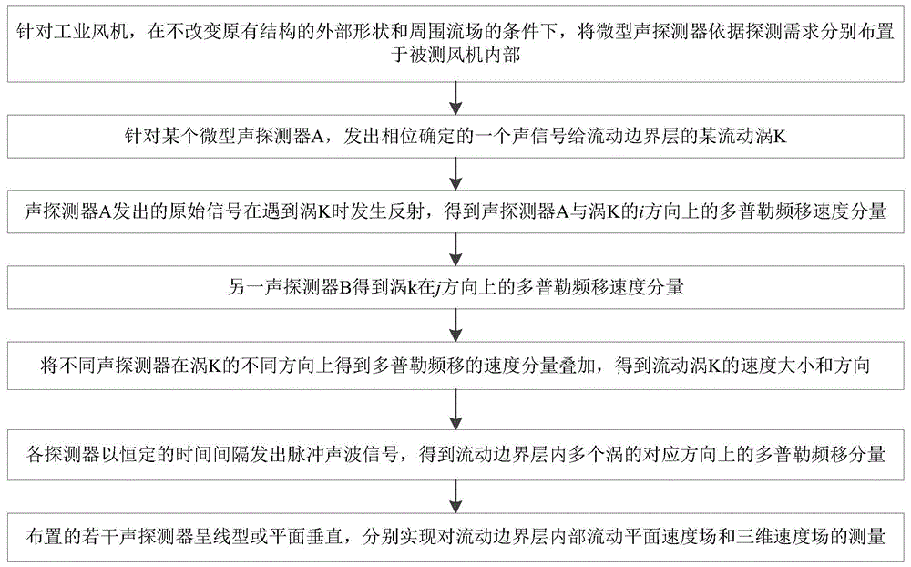
图1为本发明一种通过非外伸式微缩声探测器进行流动测量的方法流程图;1 is a flow chart of a method for performing flow measurement by a non-extended microscopic acoustic detector according to the present invention;
图2为本发明实施例采用的工业轴流风机结构示意图;2 is a schematic structural diagram of an industrial axial flow fan adopted in an embodiment of the present invention;
图3为本发明实施例采用的工业轴流风机旋叶结构示意图;FIG. 3 is a schematic structural diagram of a rotary blade of an industrial axial flow fan adopted in an embodiment of the present invention;
图4为本发明反映流场中某一涡的探测于二维平面速度显示示意图;4 is a schematic diagram of the present invention reflecting the detection of a certain vortex in the flow field in a two-dimensional plane velocity display;
图5为本发明若干声探测器的散点状布置示意图。FIG. 5 is a schematic diagram of a scattered point arrangement of several acoustic detectors of the present invention.
具体实施方式Detailed ways
下面将结合附图和实例对本发明作进一步的详细说明。The present invention will be further described in detail below in conjunction with the accompanying drawings and examples.
本发明涉及一种测量流体流动边界层的非外延伸、非突触式的声学测量方法,是一种针对流动的快速显示方法,且这种方法对流动自身的运动影响尽可能的小。从自身原理上来说,通过声与涡旋速度的直接关系,对附面边界层的流场显示。以飞机短距起飞为例,此时,飞机起飞的最小喷量就成了一个核心要解决的问题。飞机通过对外部流场的迅速观测来进行控制这一参数,就要尽可能快的捕捉外部附面流场的涡,这种时候就可以通过机翼上内置的声探测器来测量边界层的湍流特征,来达到目的。而由于流动直接会影响结构内部力,所以工业设备也需要直接检测这种流场带来的附加载荷,而关于载荷的最佳信息提取参数是边界层,因为它们彼此紧密相连。由此可以通过这种方法,实现二维或三维速度边界层的快速显示。The present invention relates to a non-extension and non-synaptic acoustic measurement method for measuring the boundary layer of fluid flow, which is a fast display method for the flow, and this method has as little influence on the movement of the flow itself as possible. In principle, the flow field of the boundary layer is displayed through the direct relationship between sound and vortex velocity. Taking the short-distance take-off of an aircraft as an example, at this time, the minimum spray volume of the aircraft for take-off has become a core problem to be solved. The aircraft controls this parameter through the rapid observation of the external flow field. It is necessary to capture the vortex of the external boundary flow field as quickly as possible. At this time, the built-in acoustic detector on the wing can be used to measure the boundary layer. Turbulence characteristics to achieve the purpose. And because the flow directly affects the internal forces of the structure, the industrial equipment also needs to directly detect the additional load brought by this flow field, and the best information extraction parameter about the load is the boundary layer, because they are closely connected to each other. Therefore, by this method, the rapid display of the two-dimensional or three-dimensional velocity boundary layer can be realized.
本发明采用了声探测器,通过边界层内涡对声音信号反射后频率与强度的影响和变化,得到边界层内某一方向的速度大小,在多探测器布置和相位变换下,获得了边界层内某一点或者平面内的速度大小、方向甚至是其中的湍流结构显示的技术效果。The invention adopts an acoustic detector, and obtains the velocity in a certain direction in the boundary layer through the influence and change of the frequency and intensity of the sound signal after reflection by the vortices in the boundary layer. Under the arrangement of multiple detectors and phase transformation, the boundary is obtained. The technical effect of the magnitude, direction, and even the turbulent structure of the velocity at a point within a layer or in a plane.
如图1所示,具体步骤如下:As shown in Figure 1, the specific steps are as follows:
步骤一、针对工业风机,在不改变原有结构的外部形状和周围流场的条件下,将微型声探测器依据探测需求分别布置于被测风机内部;Step 1. For the industrial fan, under the condition of not changing the external shape of the original structure and the surrounding flow field, the micro acoustic detectors are respectively arranged inside the fan under test according to the detection requirements;
如图2和图3所示,对于这种风机叶片主要关心的流动为流向和径向流动两种,因此对于这种风机布置是:依据风机的叶片展长与弦长之比布置二维微型声探测器,沿叶片根部至梢部。其中,沿径向布置的一条直线的二维微型声探测器探测流管内一截面的流动现象,沿弦向一条直线布置的二维微型声探测器探测沿流向内一截面的流动现象。通过这种方法呈散点状布置于叶片内部的声探测器就可测量出内部全流场的情况。而对于三维声探测器,主要考虑声探测器的处理速度,根据精细要求可增减探测器的数目。As shown in Figure 2 and Figure 3, the flow of interest for this fan blade is the flow direction and radial flow. Therefore, for this fan arrangement, the two-dimensional microscopic flow is arranged according to the ratio of the blade length to the chord length of the fan. Acoustic detector, along the blade root to tip. Among them, a two-dimensional micro-acoustic detector arranged in a straight line along the radial direction detects the flow phenomenon in a cross-section in the flow pipe, and a two-dimensional micro-acoustic detector arranged in a straight line along the chord direction detects the flow phenomenon in a cross-section in the flow direction. In this way, the acoustic detectors arranged in scattered points inside the blade can measure the internal full flow field. As for the three-dimensional acoustic detector, the processing speed of the acoustic detector is mainly considered, and the number of detectors can be increased or decreased according to the fine requirements.
各微型声探测器的反馈信号可根据信号的不同,直接接入计算机或连接至专用压电信号处理设备中。The feedback signal of each miniature acoustic detector can be directly connected to the computer or connected to the special piezoelectric signal processing equipment according to the difference of the signal.
步骤二、针对某个微型声探测器A,发出相位确定的一个声信号给流动边界层内存在的某流动涡K;Step 2: For a certain micro-acoustic detector A, send an acoustic signal whose phase is determined to a certain flow vortex K existing in the flow boundary layer;
步骤三、声探测器A发出的原始信号在遇到涡K时发生反射,得到声探测器A与涡K的i方向上的多普勒频移速度分量
如图4所示,由于多普勒效应,原有发出声信号的相位和频率发生变化并反射回声探测器上,在声探测器与涡的方向存在着多普勒频移,通过数学计算直接转换成该方向的速度信息:As shown in Figure 4, due to the Doppler effect, the phase and frequency of the original sound signal changes and is reflected on the echo detector. There is a Doppler frequency shift in the direction of the sound detector and the vortex. Convert to velocity information in that direction:

式中:ν为原始信号频率;为流场湍流中涡的流动方向;

步骤五、同理,另一声探测器B得到涡k在j方向上的多普勒频移速度分量
步骤六、将不同声探测器在涡K的不同方向上得到多普勒频移的速度分量叠加,得到流动涡K的速度大小和方向;Step 6. The velocity components of the Doppler frequency shift obtained by different acoustic detectors in different directions of the vortex K are superimposed to obtain the velocity magnitude and direction of the flow vortex K;
涡k的速度vk:
步骤七、各探测器以恒定的时间间隔发出脉冲声波信号,得到流动边界层内多个涡的对应方向上的多普勒频移分量。Step 7: Each detector sends out pulsed acoustic wave signals at constant time intervals to obtain Doppler frequency shift components in the corresponding directions of the multiple vortices in the flow boundary layer.
确保被散射信号可以从原始信号中分离出来,同一声探测器发出信号的相位变化可以保证同时接收和处理多个反射信号;由此一个声探测器得到了边界层流动内多个涡的某一方向速度分量。声探测器A与各涡的i方向上均产生多普勒频移分量;声探测器B与各涡的j方向上均产生多普勒频移分量;To ensure that the scattered signal can be separated from the original signal, the phase change of the signal emitted by the same acoustic detector can ensure that multiple reflected signals are received and processed at the same time; thus, one acoustic detector can obtain a certain one of the multiple vortices in the boundary layer flow. Directional velocity component. Doppler frequency shift components are generated in the i direction of the acoustic detector A and each vortex; Doppler frequency shift components are generated in the j direction of the acoustic detector B and each vortex;
步骤八、布置的若干声探测器呈线型或平面垂直,分别实现对流动边界层内部流动平面速度场和三维速度场的测量。Step 8: The arranged acoustic detectors are linear or vertical to measure the flow plane velocity field and the three-dimensional velocity field in the flow boundary layer respectively.
如图5所示,若干声探测器的布置方式为散点状。As shown in Figure 5, the arrangement of several acoustic detectors is scattered.
Claims (4)


Priority Applications (1)
| Application Number | Priority Date | Filing Date | Title |
|---|---|---|---|
| CN201810604669.XA CN108802423B (en) | 2018-06-13 | 2018-06-13 | Method for flow measurement through non-overhanging type micro-sound detector |
Applications Claiming Priority (1)
| Application Number | Priority Date | Filing Date | Title |
|---|---|---|---|
| CN201810604669.XA CN108802423B (en) | 2018-06-13 | 2018-06-13 | Method for flow measurement through non-overhanging type micro-sound detector |
Publications (2)
| Publication Number | Publication Date |
|---|---|
| CN108802423A CN108802423A (en) | 2018-11-13 |
| CN108802423B true CN108802423B (en) | 2020-01-03 |
Family
ID=64085619
Family Applications (1)
| Application Number | Title | Priority Date | Filing Date |
|---|---|---|---|
| CN201810604669.XA Active CN108802423B (en) | 2018-06-13 | 2018-06-13 | Method for flow measurement through non-overhanging type micro-sound detector |
Country Status (1)
| Country | Link |
|---|---|
| CN (1) | CN108802423B (en) |
Citations (6)
| Publication number | Priority date | Publication date | Assignee | Title |
|---|---|---|---|---|
| US6644128B1 (en) * | 2000-03-15 | 2003-11-11 | Abb Research Ltd | Flow meter |
| CN1608198A (en) * | 2001-10-26 | 2005-04-20 | 东京电力株式会社 | Doppler Ultrasonic Flowmeter |
| US7437947B1 (en) * | 2007-06-11 | 2008-10-21 | National Taiwan University Of Science And Technology | Acoustic method for measuring flow velocity of fluid |
| CN104865404A (en) * | 2015-06-17 | 2015-08-26 | 王三名 | Acoustic-Doppler flow velocity measuring instrument and flow velocity measuring method |
| CN107102166A (en) * | 2017-03-28 | 2017-08-29 | 天津大学 | Ultrasonic Doppler multiphase flow velocity flow profile detection device |
| CN107607158A (en) * | 2017-09-18 | 2018-01-19 | 李言钦 | System for measuring axial flow velocity distribution and flow in pipe by acoustic method |
-
2018
- 2018-06-13 CN CN201810604669.XA patent/CN108802423B/en active Active
Patent Citations (6)
| Publication number | Priority date | Publication date | Assignee | Title |
|---|---|---|---|---|
| US6644128B1 (en) * | 2000-03-15 | 2003-11-11 | Abb Research Ltd | Flow meter |
| CN1608198A (en) * | 2001-10-26 | 2005-04-20 | 东京电力株式会社 | Doppler Ultrasonic Flowmeter |
| US7437947B1 (en) * | 2007-06-11 | 2008-10-21 | National Taiwan University Of Science And Technology | Acoustic method for measuring flow velocity of fluid |
| CN104865404A (en) * | 2015-06-17 | 2015-08-26 | 王三名 | Acoustic-Doppler flow velocity measuring instrument and flow velocity measuring method |
| CN107102166A (en) * | 2017-03-28 | 2017-08-29 | 天津大学 | Ultrasonic Doppler multiphase flow velocity flow profile detection device |
| CN107607158A (en) * | 2017-09-18 | 2018-01-19 | 李言钦 | System for measuring axial flow velocity distribution and flow in pipe by acoustic method |
Also Published As
| Publication number | Publication date |
|---|---|
| CN108802423A (en) | 2018-11-13 |
Similar Documents
| Publication | Publication Date | Title |
|---|---|---|
| Pattenden et al. | Measurements of the flow over a low-aspect-ratio cylinder mounted on a ground plane | |
| Chesnakas et al. | Detailed investigation of the three-dimensional separation about a 6: 1 prolate spheroid | |
| US5299455A (en) | Method and instrumentation system for measuring airspeed and flow angle | |
| Gardner et al. | Investigation of three-dimensional dynamic stall on an airfoil using fast-response pressure-sensitive paint | |
| Chesnakas et al. | Measurements of the Turbulence Structure in the Vicinity of a 3-D Separation | |
| CN108802423B (en) | Method for flow measurement through non-overhanging type micro-sound detector | |
| Younes et al. | Spectral analysis of the transition to turbulence downstream a delta winglet pair vortex generator in an airflow channel | |
| Diribarne et al. | Investigation of properties of superfluid He 4 turbulence using a hot-wire signal | |
| RU127473U1 (en) | VORTEX SENSOR OF AERODYNAMIC ANGLE AND TRUE AIR SPEED | |
| Satta et al. | Velocity and turbulence measurements in a separating boundary layer with and without passive flow control | |
| Devenport et al. | Time-dependent structure in wing-body junction flows | |
| Zhang et al. | Development of pulse-type skin friction balance use in shock tunnel | |
| Green et al. | Measurement of three-dimensional unsteady flows using an inexpensive multiple disk probe | |
| Yao et al. | Theoretical calibration and experimental test of hemispherical seven-hole probe under 3-D flow field in wind tunnel | |
| Barsov et al. | COMPARATIVE ANALYSIS OF THE AIR FLOW VELOCITY DETERMINATION METHODS | |
| RU2506596C1 (en) | Vortex sensor of aerodynamic angle and true air speed | |
| Borah et al. | Vortex Shedding Analysis in the Wake of a Flat Plate at Low Incidence and Low Reynolds Number | |
| Cejpek et al. | Analysis of velocity profile measurements obtained by different methods in low-speed, small-scale wind tunnel | |
| Holdø et al. | Flows generated by the interaction of an inlet and a cross-flow | |
| Soldatkina et al. | Vortex sensor of aerodynamic angle and true airspeed with enhanced functionality | |
| Bur et al. | An overview of recent experimental studies conducted in ONERA S3Ch transonic wind tunnel | |
| Chesnakas et al. | Three-dimensional turbulence structure in the vicinity of a 3-D separation | |
| Kravtsova | Methods of Cavitation Flows Investigation | |
| Lehr et al. | Application of a particle image velocimetry (PIV) system to the periodic unsteady flow around an isolated compressor blade | |
| Verma et al. | Wake Shedding Characteristics of an Airfoil in Low Reynolds Number Regime |
Legal Events
| Date | Code | Title | Description |
|---|---|---|---|
| PB01 | Publication | ||
| PB01 | Publication | ||
| SE01 | Entry into force of request for substantive examination | ||
| SE01 | Entry into force of request for substantive examination | ||
| GR01 | Patent grant | ||
| GR01 | Patent grant |