CN108802435B - A kind of power automation comprehensive test device - Google Patents

A kind of power automation comprehensive test device Download PDF

Info

Publication number
CN108802435B
CN108802435B CN201810302548.XA CN201810302548A CN108802435B CN 108802435 B CN108802435 B CN 108802435B CN 201810302548 A CN201810302548 A CN 201810302548A CN 108802435 B CN108802435 B CN 108802435B
Authority
CN
China
Prior art keywords
center line
telescopic
opening
neck opening
spring
Prior art date
Legal status (The legal status is an assumption and is not a legal conclusion. Google has not performed a legal analysis and makes no representation as to the accuracy of the status listed.)
Active
Application number
CN201810302548.XA
Other languages
Chinese (zh)
Other versions
CN108802435A (en
Inventor
王俏俏
董晨晖
林祺蓉
刘淑莉
李莉
马洪文
施雨
殷洪华
刘红霞
张来
Current Assignee (The listed assignees may be inaccurate. Google has not performed a legal analysis and makes no representation or warranty as to the accuracy of the list.)
Chuanhaiju Chengdu Intellectual Property Operation Co ltd
Original Assignee
Anhui Tianying Electric Transmission Co ltd
Priority date (The priority date is an assumption and is not a legal conclusion. Google has not performed a legal analysis and makes no representation as to the accuracy of the date listed.)
Filing date
Publication date
Application filed by Anhui Tianying Electric Transmission Co ltd filed Critical Anhui Tianying Electric Transmission Co ltd
Priority to CN201810302548.XA priority Critical patent/CN108802435B/en
Publication of CN108802435A publication Critical patent/CN108802435A/en
Application granted granted Critical
Publication of CN108802435B publication Critical patent/CN108802435B/en
Active legal-status Critical Current
Anticipated expiration legal-status Critical

Links

Images

Classifications

    • GPHYSICS
    • G01MEASURING; TESTING
    • G01RMEASURING ELECTRIC VARIABLES; MEASURING MAGNETIC VARIABLES
    • G01R1/00Details of instruments or arrangements of the types included in groups G01R5/00 - G01R13/00 and G01R31/00
    • G01R1/02General constructional details

Landscapes

  • Physics & Mathematics (AREA)
  • General Physics & Mathematics (AREA)
  • Vehicle Cleaning, Maintenance, Repair, Refitting, And Outriggers (AREA)
  • Testing Relating To Insulation (AREA)

Abstract

本发明公开了一种电力自动化综合测试装置,包括保护壳体、移动轮和内插孔,所述保护壳体的左右两侧均安装有伸缩提手,所述橡胶板的上方安装有测试主体,所述保护壳体的上方设置有转轴,所述测试主体的前方上下两侧均安装有限位块,所述移动轮位于保护壳体的后方,所述内插孔位于外插孔的内部,且内插孔的前方安装有弹簧块,所述弹簧块的前方安装有伸缩弹簧,且伸缩弹簧的前方设置有橡胶球,所述保护壳体的下表面安装有螺纹柱。该电力自动化综合测试装置设置有螺纹柱,使得装置在使用过程中,通过与螺纹套筒的配合使用,增加了装置与地面的高度,保证了装置的安全,并配合滚球使用,便于装置在使用过程中的移动。

Figure 201810302548

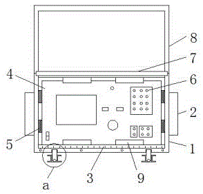
The invention discloses a comprehensive testing device for electric power automation, comprising a protective casing, a moving wheel and an inner socket. Telescopic handles are installed on the left and right sides of the protective casing, and a test body is installed above the rubber plate. , the top of the protective casing is provided with a rotating shaft, the upper and lower sides of the test body are installed with limit blocks, the moving wheel is located at the rear of the protective casing, the inner socket is located inside the outer socket, A spring block is installed in front of the inner socket, a telescopic spring is installed in front of the spring block, a rubber ball is installed in front of the extension spring, and a threaded column is installed on the lower surface of the protective shell. The electric power automation comprehensive test device is provided with a threaded column, so that the device can be used in conjunction with a threaded sleeve to increase the height of the device and the ground to ensure the safety of the device. Movement during use.

Figure 201810302548

Description

Electric power automation comprehensive test device
Technical Field
The invention relates to the technical field of electric power automation, in particular to an electric power automation comprehensive testing device.
Background
The whole height of device need be increased to other objects to current automatic integrated test device of electric power in the use for there is certain inconvenience in the device in the use, and current automatic integrated test device of electric power is after using, can not effectually carry out water protection to the jack, makes the device meet water the time, very easily leads to liquid to flow in the inside of device from the jack.
We propose an electric power automation comprehensive test device in order to solve the problems set forth above.
Disclosure of Invention
The invention aims to provide an electric power automation comprehensive test device, which solves the problems that the electric power automation comprehensive test device in the current market proposed by the background art is inconvenient to use and jacks cannot be waterproof.
In order to achieve the purpose, the invention provides the following technical scheme: an electric power automation comprehensive test device comprises a protection shell, a moving wheel and an inner inserting hole, wherein telescopic handles are installed on the left side and the right side of the protection shell, a rubber plate is laid below the inner side of the protection shell, a test main body is installed above the rubber plate, fixed blocks are installed on the left side and the right side of the test main body, an outer inserting hole is installed in front of the test main body, a rotating shaft is arranged above the protection shell, a protective cover is installed above the rotating shaft, limit blocks are installed on the upper side and the lower side of the front of the test main body, the moving wheel is located behind the protection shell, the inner inserting hole is located inside the outer inserting hole, a spring block is installed in front of the inner inserting hole, a telescopic spring is installed in front of the spring block, a rubber ball is arranged in front of the telescopic spring, a threaded column is installed on the lower surface of the protection shell, and, and the rolling ball is arranged below the threaded column, the inner part of the outer plug hole comprises an opening and a neck opening, the neck opening is arranged behind the opening, the height of the center line of the neck opening is lower than that of the center line of the opening, the center line of the neck opening is parallel to the center line of the opening, the center line of the neck opening and the center line of the inner plug hole are superposed, the center line of the inner plug hole is higher than the upper surface of the spring block, the upper surface of the spring block is lower than the lowest point of the neck opening, the diameter of the neck opening is smaller than the outer diameter of the rubber ball, and the rubber ball forms a telescopic structure through the telescopic.
Preferably, the number of the telescopic handles is 2, and the 2 telescopic handles are symmetrical about the central line of the protection shell.
Preferably, the fixed blocks are uniformly distributed on the side surface inside the protective shell, and the fixed blocks are of cylindrical structures.
Preferably, the threaded columns and the protective shell form a detachable structure, and the number of the threaded columns is 4, and the 4 threaded columns are symmetrical about the central line of the protective shell.
Compared with the prior art, the invention has the beneficial effects that: the electric power automatic comprehensive testing device is provided with a fixed block and a limiting block, wherein the fixed block and the limiting block are both made of rubber materials, have certain elasticity and certain buffering capacity, can effectively protect the device, and are provided with a protective shell which is made of plastic materials and has good waterproof and dustproof performances, the service life of the device is prolonged, the rubber ball is arranged, so that when the device is idle, the rubber ball can block the neck opening of the outer inserting hole through the elasticity of a telescopic spring, thereby blocking the outer inserting hole, effectively blocking the external liquid and dust infiltration, the rubber ball is made of rubber materials and has certain deformation capacity, the rubber ball is more tightly attached to the neck opening, and the moving wheel is arranged, so that the device can be conveniently moved when being matched with a telescopic handle, is convenient to carry and transport the device, and is provided with a threaded column, the device is matched with the threaded sleeve to use in the using process, the height between the device and the ground is increased, the safety of the device is guaranteed, and the device is matched with the rolling ball to use, so that the device can move in the using process conveniently.
Drawings
FIG. 1 is a schematic front view of the present invention;
FIG. 2 is a schematic side view of the present invention;
FIG. 3 is a schematic cross-sectional view of an outer socket according to the present invention;
fig. 4 is an enlarged schematic view of a portion of fig. 1 according to the present invention.
In the figure: 1. a protective housing; 2. a telescopic handle; 3. a rubber plate; 4. testing the subject; 5. a fixed block; 6. an outer plug hole; 601. an opening; 602. a neck opening; 7. a rotating shaft; 8. a protective cover; 9. a limiting block; 10. a moving wheel; 11. an inner inserting hole; 12. a spring block; 13. a tension spring; 14. a rubber ball; 15. a threaded post; 16. a threaded sleeve; 17. a ball.
Detailed Description
The technical solutions in the embodiments of the present invention will be clearly and completely described below with reference to the drawings in the embodiments of the present invention, and it is obvious that the described embodiments are only a part of the embodiments of the present invention, and not all of the embodiments. All other embodiments, which can be derived by a person skilled in the art from the embodiments given herein without making any creative effort, shall fall within the protection scope of the present invention.
In the description of the present invention, it should be noted that the terms "center", "upper", "lower", "left", "right", "vertical", "horizontal", "inner", "outer", and the like indicate orientations or positional relationships based on the orientations or positional relationships shown in the drawings, and are only for convenience of description and simplicity of description, but do not indicate or imply that the device or element referred to must have a specific orientation, be constructed and operated in a specific orientation, and thus, should not be construed as limiting the present invention. Furthermore, the terms "first," "second," and "third" are used for descriptive purposes only and are not to be construed as indicating or implying relative importance.
Referring to fig. 1-4, the present invention provides a technical solution: an automatic comprehensive testing device for electric power comprises a protective shell 1, a telescopic handle 2, a rubber plate 3, a testing main body 4, a fixed block 5, an outer inserting hole 6, a rotating shaft 7, a protective cover 8, a limiting block 9, a moving wheel 10, an inner inserting hole 11, a spring block 12, a telescopic spring 13, a rubber ball 14, a threaded column 15, a threaded sleeve 16 and a rolling ball 17, wherein the telescopic handle 2 is installed on the left side and the right side of the protective shell 1, the rubber plate 3 is laid below the inner side of the protective shell 1, the telescopic handle 2 is provided with 2, the 2 telescopic handles 2 are symmetrical about the central line of the protective shell 1, a telescopic structure is adopted, the device can be conveniently and rapidly moved when being used by matching with the moving wheel 10, the testing main body 4 is installed above the rubber plate 3, the fixed blocks 5 are installed on the left side and the right side of the testing main body 4, the outer inserting, the fixed block 5 is uniformly distributed on the side surface of the inner part of the protective shell 1, the fixed block 5 is of a cylindrical structure, the fixed block 5 is made of rubber and has certain elasticity, and can buffer the external vibration to a certain extent, so as to ensure the safety of the test main body 4, the inner part of the outer inserting hole 6 comprises an opening 601 and a neck opening 602, a neck opening 602 is arranged behind the opening 601, the height of the center line of the neck opening 602 is lower than that of the center line of the opening 601, the center line of the neck opening 602 is parallel to the center line of the opening 601, the height of the center line of the neck opening 602 is lower than that of the center line of the opening 601, so that when the outer inserting hole 6 is inserted into a connector, the center height of the connector is slightly higher than that of the center line of the neck opening 602, the center line of the connector is higher than the center point of the rubber ball 14, the rubber ball 14 is, a protective cover 8 is arranged above the rotating shaft 7, the upper and lower sides in front of the test main body 4 are respectively provided with a limit block 9, the moving wheel 10 is positioned at the rear of the protective shell 1, the inner inserting hole 11 is positioned inside the outer inserting hole 6, the spring block 12 is arranged in front of the inner inserting hole 11, the central line of the neck opening 602 is superposed with the central line of the inner inserting hole 11, the central line of the inner inserting hole 11 is higher than the upper surface of the spring block 12, the upper surface of the spring block 12 is lower than the lowest point of the neck opening 602, the diameter of the neck opening 602 is smaller than the outer diameter of the rubber ball 14, and the rubber ball 14 forms a telescopic structure through the telescopic spring 13, so that when the device is idle, the rubber ball 14 blocks the neck opening 602 under the elastic action of the telescopic spring 13, thereby effectively preventing the inflow of liquid and ensuring the safety of the device, the telescopic spring 13 is arranged in front of the spring, the lower surface mounting of protection casing 1 has screw thread post 15, and the outside of screw thread post 15 is connected with threaded sleeve 16 to spin 17 is installed to the below of screw thread post 15, and screw thread post 15 constitutes dismantlement structure with protection casing 1, and screw thread post 15 is provided with 4, and 4 screw thread posts 15 are symmetrical about the central line of protection casing 1, adopt the dismantlement structure, the installation of the screw thread post 15 of being convenient for.
The working principle is as follows: when the power automatic comprehensive test device is used, firstly, the device is put to a proper position, then according to different situations of the place, whether the threaded column 15 and the threaded sleeve 16 are additionally arranged or not is selected, when water stain exists on the ground or the height is insufficient, the threaded column 15 is connected with the protective shell 1, then the threaded sleeve 16 is connected with the threaded column 15, the lower surface of the threaded sleeve 16 is lower than the lowest point of the rolling ball 17, so that the device can be used, before the device is used, the protective cover 8 of the device is firstly opened around the rotating shaft 7, so that the external joint is inserted into the external inserting hole 6, when the joint is inserted into the external inserting hole 6, the rubber ball 14 can be shifted to the lower part, so that the rubber ball enters the internal inserting hole 11, then the device is used, in the using process, the rolling ball 17 can be exposed by rotating the threaded sleeve 16, so that the movement of the device is convenient, after the use, the joint is withdrawn from the internal inserting hole, rubber ball 14 is under expanding spring 13's effect, can plug up neck finish 602, thereby the effectual unobstructed of outer plug 6 that has blocked, prevent liquid inflow in the inside of outer plug 6, increase the waterproof performance of device, close visor 8 after the use, carry through flexible handle 2 and take the device, the use of wheel 10 is removed in the cooperation, the removal of convenience of installation, and the vibrations that produce in the removal process, can be absorbed by rubber slab 3 and fixed block 5, guarantee the safety of device, the content that does not make detailed description in this description belongs to the well-known prior art of the professional skilled in the art in this field.
Although the present invention has been described in detail with reference to the foregoing embodiments, it will be apparent to those skilled in the art that various changes in the embodiments and/or modifications of the invention can be made, and equivalents and modifications of some features of the invention can be made without departing from the spirit and scope of the invention.

Claims (4)

1. An electric power automation comprehensive test device, including protection casing (1), removal wheel (10) and interior plug hole (11), its characterized in that: the protection device is characterized in that telescopic handles (2) are mounted on the left side and the right side of the protection shell (1), a rubber plate (3) is laid below the inner side of the protection shell (1), a test main body (4) is mounted above the rubber plate (3), fixed blocks (5) are mounted on the left side and the right side of the test main body (4), an outer inserting hole (6) is mounted in front of the test main body (4), a rotating shaft (7) is arranged above the protection shell (1), a protective cover (8) is mounted above the rotating shaft (7), limiting blocks (9) are mounted on the upper side and the lower side of the front of the test main body (4), a moving wheel (10) is located behind the protection shell (1), an inner inserting hole (11) is located inside the outer inserting hole (6), a spring block (12) is mounted in front of the inner inserting hole (11), a telescopic spring (13) is mounted in front of the spring block, a rubber ball (14) is arranged in front of the telescopic spring (13), a threaded column (15) is arranged on the lower surface of the protective shell (1), a threaded sleeve (16) is connected to the outer side of the threaded column (15), a rolling ball (17) is arranged below the threaded column (15), an opening (601) and a neck opening (602) are arranged inside the outer plug hole (6), a neck opening (602) is arranged behind the opening (601), the height of the center line of the neck opening (602) is lower than that of the center line of the opening (601), the center line of the neck opening (602) is parallel to that of the opening (601), the center line of the neck opening (602) and the center line of the inner plug hole (11) are overlapped, the center line of the inner plug hole (11) is higher than the upper surface of the spring block (12), the upper surface of the spring block (12) is lower than the lowest point of the neck opening (602), and the diameter of the neck opening (602) is smaller than the outer diameter of the rubber ball, and the rubber ball (14) forms a telescopic structure through a telescopic spring (13).
2. The automatic integrated test device of electric power of claim 1, characterized in that: the number of the telescopic handles (2) is 2, and the 2 telescopic handles (2) are symmetrical about the central line of the protection shell (1).
3. The automatic integrated test device of electric power of claim 1, characterized in that: fixed block (5) evenly distributed is at the inside side surface of protection casing (1), and fixed block (5) are cylindric structure.
4. The automatic integrated test device of electric power of claim 1, characterized in that: the threaded columns (15) and the protective shell (1) form a disassembly structure, the number of the threaded columns (15) is 4, and the 4 threaded columns (15) are symmetrical about the center line of the protective shell (1).
CN201810302548.XA 2018-04-05 2018-04-05 A kind of power automation comprehensive test device Active CN108802435B (en)

Priority Applications (1)

Application Number Priority Date Filing Date Title
CN201810302548.XA CN108802435B (en) 2018-04-05 2018-04-05 A kind of power automation comprehensive test device

Applications Claiming Priority (1)

Application Number Priority Date Filing Date Title
CN201810302548.XA CN108802435B (en) 2018-04-05 2018-04-05 A kind of power automation comprehensive test device

Publications (2)

Publication Number Publication Date
CN108802435A CN108802435A (en) 2018-11-13
CN108802435B true CN108802435B (en) 2021-06-22

Family

ID=64094863

Family Applications (1)

Application Number Title Priority Date Filing Date
CN201810302548.XA Active CN108802435B (en) 2018-04-05 2018-04-05 A kind of power automation comprehensive test device

Country Status (1)

Country Link
CN (1) CN108802435B (en)

Citations (6)

* Cited by examiner, † Cited by third party
Publication number Priority date Publication date Assignee Title
CN1253218A (en) * 1998-10-30 2000-05-17 泷源制造株式会社 Waterproof cover for lock
CN1264195A (en) * 1999-01-29 2000-08-23 住友电装株式会社 Closing plug for waterproof connector and waterproof connector
JP2005009927A (en) * 2003-06-17 2005-01-13 Tesu Hanbai Kk Spring probe
CN201795158U (en) * 2010-07-13 2011-04-13 卫艺文 Leakage-preventive water faucet
CN202049184U (en) * 2011-04-02 2011-11-23 上海奉义龙电子有限公司 Streamline waterproof type watthour meter
JP2015049076A (en) * 2013-08-30 2015-03-16 三菱電機株式会社 Contact and measuring device

Family Cites Families (10)

* Cited by examiner, † Cited by third party
Publication number Priority date Publication date Assignee Title
CN2397327Y (en) * 1999-08-20 2000-09-20 段梦麟 Three controlling check valve
CN202854179U (en) * 2012-10-18 2013-04-03 青海电力科学试验研究院 Integrated test system equipment box of power plant
CN203106344U (en) * 2013-03-13 2013-08-07 何家华 Dining table easy to move
CN203394424U (en) * 2013-06-08 2014-01-15 中国石油天然气股份有限公司 A fast and controllable anti-jet plugging
CN204885628U (en) * 2015-07-31 2015-12-16 徐月苗 Waterproof shock attenuation wiring board
CN205120542U (en) * 2015-11-18 2016-03-30 浙江省水利河口研究院 Automatic water system that adds of concrete penetrometer
CN105746374B (en) * 2016-03-22 2019-03-05 安徽斯高德农业科技有限公司 A kind of livestock breed aquatics Automatic Water System
CN106313921A (en) * 2016-08-19 2017-01-11 陈思奇 Leakage preventing finance seal
CN205976592U (en) * 2016-08-20 2017-02-22 沈坚雷 Sealing needle
CN206015809U (en) * 2016-08-25 2017-03-15 无锡市东北塘永丰橡塑厂 Water tube hose under a kind of platform basin odor-resistant anti-clogging

Patent Citations (6)

* Cited by examiner, † Cited by third party
Publication number Priority date Publication date Assignee Title
CN1253218A (en) * 1998-10-30 2000-05-17 泷源制造株式会社 Waterproof cover for lock
CN1264195A (en) * 1999-01-29 2000-08-23 住友电装株式会社 Closing plug for waterproof connector and waterproof connector
JP2005009927A (en) * 2003-06-17 2005-01-13 Tesu Hanbai Kk Spring probe
CN201795158U (en) * 2010-07-13 2011-04-13 卫艺文 Leakage-preventive water faucet
CN202049184U (en) * 2011-04-02 2011-11-23 上海奉义龙电子有限公司 Streamline waterproof type watthour meter
JP2015049076A (en) * 2013-08-30 2015-03-16 三菱電機株式会社 Contact and measuring device

Non-Patent Citations (1)

* Cited by examiner, † Cited by third party
Title
一种防水防盐雾圆形电连接器的结构设计;邱云凤;《机电元件》;20031231;第10-13页,第17页 *

Also Published As

Publication number Publication date
CN108802435A (en) 2018-11-13

Similar Documents

Publication Publication Date Title
CN107227790A (en) A kind of discharge structure for underground garage
CN210805966U (en) Waterproof filter
CN108802435B (en) A kind of power automation comprehensive test device
CN206815937U (en) One kind communication pole line rising device
CN105150728A (en) Novel blackboard eraser
CN212875931U (en) A New Portable Integrated Control Ball
CN212838531U (en) A sewage discharge device for garden cleaning
CN211929776U (en) A waterproof plug-in structure for connectors
CN212405421U (en) Water conservancy construction is with having floor drain that prevents blockking up structure
CN206997141U (en) Spherical camera wipes instrument soon
CN207685939U (en) A kind of outlet device of anti-clogging leakproof
CN209761798U (en) portable handheld small fan
CN208216915U (en) Lithium battery water-inlet-proof for bicycle after-frame protects structure
CN204930918U (en) One is portable sees figure paper apparatus
CN210627249U (en) A retractable waterproof U disk
CN220858697U (en) Water cavity structure is prevented to power
CN106129702A (en) A kind of carbon fiber composite core wire traction wire clamp optical protective structure
CN208650650U (en) The environmentally friendly sound insulation protective fence of construction
CN207053224U (en) A kind of Portable power source
CN206272298U (en) A charging pile convenient for fixing charging lines
CN205850096U (en) A kind of tilt autostop treadmill
CN216449551U (en) A detection device for sewage treatment
CN217209629U (en) Height-adjustable humidifier shell
CN210739722U (en) A drainage pipe detection crawling device
CN222110849U (en) A ball pump that can conveniently store ball needles

Legal Events

Date Code Title Description
PB01 Publication
PB01 Publication
SE01 Entry into force of request for substantive examination
TA01 Transfer of patent application right

Effective date of registration: 20210607

Address after: 236700 No.3 Changchun Road, Lixin Industrial Park, Bozhou City, Anhui Province

Applicant after: ANHUI TIANYING ELECTRIC TRANSMISSION Co.,Ltd.

Address before: Jinan power supply company, 238 Luoyuan street, Jinan City, Shandong Province, 250012

Applicant before: Dong Chenhui

GR01 Patent grant
GR01 Patent grant
TR01 Transfer of patent right

Effective date of registration: 20250922

Address after: Room 2506, Floor 25, Building 1, No. 188, Section 2, Renmin North Road, Jinniu District, Chengdu, Sichuan 610,000

Patentee after: Chuanhaiju (Chengdu) Intellectual Property Operation Co.,Ltd.

Country or region after: China

Address before: 236700 No.3 Changchun Road, Lixin Industrial Park, Bozhou City, Anhui Province

Patentee before: ANHUI TIANYING ELECTRIC TRANSMISSION CO.,LTD.

Country or region before: China