CN1088024C - Method and apparatus for forming strings of pocketed springs - Google Patents
Method and apparatus for forming strings of pocketed springs Download PDFInfo
- Publication number
- CN1088024C CN1088024C CN96196143A CN96196143A CN1088024C CN 1088024 C CN1088024 C CN 1088024C CN 96196143 A CN96196143 A CN 96196143A CN 96196143 A CN96196143 A CN 96196143A CN 1088024 C CN1088024 C CN 1088024C
- Authority
- CN
- China
- Prior art keywords
- flanging
- fabric
- disc spring
- fabric pipe
- deflector elements
- Prior art date
- Legal status (The legal status is an assumption and is not a legal conclusion. Google has not performed a legal analysis and makes no representation as to the accuracy of the status listed.)
- Expired - Lifetime
Links
Images


Classifications
-
- B—PERFORMING OPERATIONS; TRANSPORTING
- B65—CONVEYING; PACKING; STORING; HANDLING THIN OR FILAMENTARY MATERIAL
- B65B—MACHINES, APPARATUS OR DEVICES FOR, OR METHODS OF, PACKAGING ARTICLES OR MATERIALS; UNPACKING
- B65B5/00—Packaging individual articles in containers or receptacles, e.g. bags, sacks, boxes, cartons, cans, jars
- B65B5/02—Machines characterised by incorporation of means for making the containers or receptacles
-
- B—PERFORMING OPERATIONS; TRANSPORTING
- B68—SADDLERY; UPHOLSTERY
- B68G—METHODS, EQUIPMENT, OR MACHINES FOR USE IN UPHOLSTERING; UPHOLSTERY NOT OTHERWISE PROVIDED FOR
- B68G9/00—Placing upholstery springs in pockets; Fitting springs in upholstery
-
- B—PERFORMING OPERATIONS; TRANSPORTING
- B68—SADDLERY; UPHOLSTERY
- B68G—METHODS, EQUIPMENT, OR MACHINES FOR USE IN UPHOLSTERING; UPHOLSTERY NOT OTHERWISE PROVIDED FOR
- B68G9/00—Placing upholstery springs in pockets; Fitting springs in upholstery
- B68G2009/005—Devices for turning the springs 90° inside the pockets
-
- Y—GENERAL TAGGING OF NEW TECHNOLOGICAL DEVELOPMENTS; GENERAL TAGGING OF CROSS-SECTIONAL TECHNOLOGIES SPANNING OVER SEVERAL SECTIONS OF THE IPC; TECHNICAL SUBJECTS COVERED BY FORMER USPC CROSS-REFERENCE ART COLLECTIONS [XRACs] AND DIGESTS
- Y10—TECHNICAL SUBJECTS COVERED BY FORMER USPC
- Y10T—TECHNICAL SUBJECTS COVERED BY FORMER US CLASSIFICATION
- Y10T29/00—Metal working
- Y10T29/48—Upholstered article making
- Y10T29/481—Method
-
- Y—GENERAL TAGGING OF NEW TECHNOLOGICAL DEVELOPMENTS; GENERAL TAGGING OF CROSS-SECTIONAL TECHNOLOGIES SPANNING OVER SEVERAL SECTIONS OF THE IPC; TECHNICAL SUBJECTS COVERED BY FORMER USPC CROSS-REFERENCE ART COLLECTIONS [XRACs] AND DIGESTS
- Y10—TECHNICAL SUBJECTS COVERED BY FORMER USPC
- Y10T—TECHNICAL SUBJECTS COVERED BY FORMER US CLASSIFICATION
- Y10T29/00—Metal working
- Y10T29/49—Method of mechanical manufacture
- Y10T29/49826—Assembling or joining
- Y10T29/49828—Progressively advancing of work assembly station or assembled portion of work
- Y10T29/49829—Advancing work to successive stations [i.e., assembly line]
-
- Y—GENERAL TAGGING OF NEW TECHNOLOGICAL DEVELOPMENTS; GENERAL TAGGING OF CROSS-SECTIONAL TECHNOLOGIES SPANNING OVER SEVERAL SECTIONS OF THE IPC; TECHNICAL SUBJECTS COVERED BY FORMER USPC CROSS-REFERENCE ART COLLECTIONS [XRACs] AND DIGESTS
- Y10—TECHNICAL SUBJECTS COVERED BY FORMER USPC
- Y10T—TECHNICAL SUBJECTS COVERED BY FORMER US CLASSIFICATION
- Y10T29/00—Metal working
- Y10T29/49—Method of mechanical manufacture
- Y10T29/49826—Assembling or joining
- Y10T29/49863—Assembling or joining with prestressing of part
- Y10T29/4987—Elastic joining of parts
- Y10T29/49872—Confining elastic part in socket
Landscapes
- Engineering & Computer Science (AREA)
- Mechanical Engineering (AREA)
- Mattresses And Other Support Structures For Chairs And Beds (AREA)
- Springs (AREA)
- Wire Processing (AREA)
- Treatment Of Fiber Materials (AREA)
- Preliminary Treatment Of Fibers (AREA)
- Constitution Of High-Frequency Heating (AREA)
- Details Of Garments (AREA)
- Auxiliary Devices For And Details Of Packaging Control (AREA)
- Lining Or Joining Of Plastics Or The Like (AREA)
Abstract
Description
技术领域technical field
本发明涉及一种用于床垫、衬垫等的弹簧装置,更具体地说,涉及一种用于形成多列封装弹簧的新的改进方法和设备,弹簧被封装在带有平重叠侧缝的外套中,这种方法和设备不会出现现有技术中所遇到的诸如错松的不利状况。The present invention relates to a spring arrangement for mattresses, pads, etc., and more particularly to a new and improved method and apparatus for forming rows of encapsulated springs encapsulated in boxes with flat overlapping side seams In the jacket, this method and device will not have the unfavorable situation such as wrong loosening encountered in the prior art.
背景技术Background technique
许多技术可以用来制造床垫,衬垫以及类似的产品。其中一种已获得广泛认可的技术是马歇尔结构。在这种结构中,内弹簧装置包括床垫或衬垫的芯部,并且由多个弹簧构成,其中每一个都单独封装在适当的织物套中。弹簧套优选地连成预定长度的列并紧密排列在一起,其纵轴相互平行并且端部构成一个平面。在床垫的结构中,这些封装弹簧阵列上通常盖有填充泡沫或编织垫,从而提供一个睡眠用的表面。Many techniques can be used to manufacture mattresses, pads, and similar products. One such technique that has gained wide acceptance is the Marshall structure. In this construction, the innerspring unit comprises the core of the mattress or pad and is constructed of a plurality of springs, each of which is individually enclosed in a suitable fabric cover. The spring sleeves are preferably connected in rows of predetermined length and arranged closely together, with their longitudinal axes parallel to each other and their ends forming a plane. In mattress construction, these arrays of encapsulated springs are typically covered with foam-filled or woven padding to provide a sleeping surface.
现有已经采用多种方法来生产多列封装盘簧。在早期的一种生产方法中,适当的编织套沿纵向对折并以一定的间距横向缝合,从而形成内部插有弹簧的套。最近,这种方法基本上被应用热敏织物和超声焊接技术而不是缝合的一种方法所取代。美国专利NO.4,234,983中公开了后一种方法生产的多列封装盘簧的一个例子,该专利授予Stumpf并且已经转让给共同受让人。如在美国专利NO.4,234,983中所公开的那样,首先将热敏织物纵向对折,再沿横穿织物纵轴的方向涂上焊料,以通过超声焊接将盘簧装入分离的套中,从而构成一列封装盘簧。将盘簧插入套中后,就沿着盘簧的靠近弹簧一端的纵缝来把套焊死。美国专利NO.4,439,977中公开了用于生产前述盘簧列的设备,该专利也授予Stumpf并且已转让给共同受让人。Various methods have been used to produce multiple rows of encapsulated coil springs. In an earlier method of production, a suitable braided sleeve was folded longitudinally in half and stitched transversely at regular intervals to form a sleeve with a spring inserted inside. More recently, this method has largely been replaced by one that applies heat-sensitive fabrics and ultrasonic welding techniques instead of stitching. An example of multiple rows of encapsulated coil springs produced by the latter method is disclosed in US Patent No. 4,234,983, issued to Stumpf and assigned to a common assignee. As disclosed in U.S. Patent No. 4,234,983, the heat-sensitive fabric is first folded in half longitudinally, and then solder is applied in a direction transverse to the longitudinal axis of the fabric, so that the coil springs are packed into separate sleeves by ultrasonic welding, thereby forming One row of encapsulated coil springs. After the coil spring is inserted into the sleeve, the sleeve is welded dead along the longitudinal seam of the coil spring near one end of the spring. An apparatus for producing the aforementioned coil spring trains is disclosed in US Patent No. 4,439,977, also issued to Stumpf and assigned to a common assignee.
上述结构的盘簧列的一个不利之处是,沿盘簧纵向的缝在封装弹簧的一端产生了两片多余的织物。沿着缝的一些多余材料在生产过程中是必需的,用来使弹簧列对准,并保证辅助焊缝有足够强度。然而,当用多列盘簧来构成内弹簧床垫或衬垫芯部时,伸出弹簧的多余材料会在床垫或衬垫的外表面垫下面产生紧固失灵,本领域中称作“错松”。当使用者躺在床垫或衬垫上时,这种错松状态会导致本不应出现的和令人讨厌的身体压迫。One disadvantage of coil spring arrays of the above construction is that the seam along the longitudinal direction of the coil springs creates two extra pieces of fabric at one end of the encased spring. Some excess material along the seam is necessary during production to align the spring columns and to ensure adequate strength of the secondary weld. However, when multiple rows of coil springs are used to construct an innerspring mattress or pad core, the excess material protruding from the springs can create a fastening failure under the outer surface of the mattress or pad, known in the art as " Wrong loose". This mislooseness can result in unwanted and annoying compression of the body when the user is lying on the mattress or pad.
人们已经试图用带有平重叠侧缝而不是顶缝的一列盘簧来消除错松。美国专利NO.4,986,518中公开了用于生产这种盘簧列的一种机器,该专利也授予Stumpf并且已转让给共同受让人。然而,这样一种机器具有用于弹簧插入的复杂提升机构,这种机器在生产条件下显得不可靠。Attempts have been made to eliminate misloosening with a row of coil springs with flat overlapping side seams rather than top seams. A machine for producing such coil spring trains is disclosed in US Patent No. 4,986,518, also issued to Stumpf and assigned to a common assignee. However, such a machine has a complex lifting mechanism for spring insertion, which appears unreliable under production conditions.
相应地,现在发现有必要在装有内弹簧装置的床垫或衬垫结构中设置平重叠侧缝。具体地说,现已发现不产生由于在盘簧的端部带有多余封装材料而产生错松的床垫或衬垫结构是比较理想的。此外,还发现使用比先前所知构造中所需封装织物更少的内弹簧结构的多列盘簧装置是比较理想的。Accordingly, it has now been found necessary to provide flat overlapping side seams in innerspring mattress or cushion constructions. In particular, it has been found that it is desirable not to create a mattress or cushion construction that is loose due to excess packing material at the ends of the coil springs. In addition, it has been found desirable to use a multi-coil coil spring arrangement utilizing less innerspring structure than previously known constructions requiring less packing fabric.
发明内容Contents of the invention
本发明的目的在于提供一种生产装在带有平重叠侧缝的封装套中的封装盘簧的方法。这种方法可有效地高效可靠地工作,克服现有技术缺点。It is an object of the present invention to provide a method of producing encapsulated coil springs housed in envelopes with flat overlapping side seams. The method can effectively work efficiently and reliably, and overcome the disadvantages of the prior art.
根据本发明的一种生成一列盘簧的方法,其中每个盘簧都封装在具有平滑重叠侧缝的单独织物袋中,该方法包括以下步骤:将细长的织物网折叠一次,从而产生一个纵向延伸的第一折边;第二次折叠该织物网,以产生一个与第一折边侧向重叠的第二纵向延伸折边,从而形成带有折边侧和底侧的织物管,折边侧上的第二折边与折边侧上的第一折边侧向重叠;使织物管纵向穿过第一偏转器部件,这样当织物管穿过第一偏转器部件时,第一偏转器部件使第二折边脱离与第一折边的重叠关系,从而在织物管中产生一个侧向延伸的开口,织物管折边侧上的第二折边与折边侧上的第一折边脱离重叠关系;将压缩盘簧插入织物管折边侧上第一和第二折边之间的开口中;使织物管穿过第二偏转器部件,这样当织物管纵向穿过第二偏转器部件时,第二偏转器部件使第二折边重新与第一折边成侧向重叠关系;连接上述侧向重叠的第一和第二折边,从而在其间形成搭焊。A method according to the invention of producing an array of coil springs, each coil spring enclosed in a separate fabric bag with smoothly overlapping side seams, comprising the steps of folding the elongated fabric web once to produce a a longitudinally extending first hem; the fabric web is folded a second time to produce a second longitudinally extending hem laterally overlapping the first hem to form a fabric tube with a hem side and a bottom side, the hem The second hem on the side side overlaps the first hem on the hem side laterally; passing the fabric tube longitudinally through the first deflector part so that when the fabric tube passes through the first deflector part, the first deflector The device member disengages the second hem from overlapping relationship with the first hem, thereby creating a laterally extending opening in the fabric tube, the second hem on the hem side of the fabric tube being in contact with the first hem on the hem side out of overlapping relationship; insert a compression coil spring into the opening between the first and second hems on the hem side of the fabric tube; pass the fabric tube through the second deflector member so that when the fabric tube passes longitudinally through the second deflector When the deflector part is used, the second deflector part brings the second flap back into a laterally overlapping relationship with the first flap; and joins said laterally overlapping first and second flaps to form a lap weld therebetween.
本发明的方法能够有效地高效可靠地工作,不会出现现有技术中所遇到的诸如错松的不利情况。The method of the invention can work effectively, efficiently and reliably without disadvantages such as wrong loosening encountered in the prior art.
附图说明Description of drawings
通过阅读下面的详细说明并参照附图,可以更明确的理解本发明的上述和另外一些新颖的特征,其中:The above and other novel features of the present invention can be more clearly understood by reading the following detailed description and referring to the accompanying drawings, in which:
图1是现有技术床垫的透视图,其中局部剖开以示出普通的内弹簧结构;Figure 1 is a perspective view of a prior art mattress, partially cut away to show a conventional innerspring structure;
图2是图1所示现有技术内弹簧的局部侧视图;Fig. 2 is a partial side view of the prior art inner spring shown in Fig. 1;
图3是根据本发明的设备的织物输送工作台的局部透视图;Figure 3 is a partial perspective view of the fabric delivery table of the apparatus according to the invention;
图4是图3的送料工作台的另一个局部透视图,织物在工作台中折叠;Figure 4 is another partial perspective view of the feeding table of Figure 3 with the fabric folded in the table;
图5是根据本发明制成的织物管的端视图;Figure 5 is an end view of a fabric tube made in accordance with the present invention;
图6是根据本发明的装置中的第一偏转工作台的端视图,示出了独创方法中的一个阶段,其中织物管的折边被分开,以便于随后在其中插入盘簧;Figure 6 is an end view of the first deflection table in the device according to the invention, showing a stage in the inventive method in which the hems of the fabric tube are separated to facilitate the subsequent insertion of coil springs therein;
图7是根据本发明的弹簧插入工作台的简图,示出了独创方法中的一个阶段,其中处于未压缩状态的弹簧在插入织物管之前进行定位;Figure 7 is a schematic diagram of a spring insertion station according to the present invention, showing a stage in the inventive method wherein the spring in its uncompressed state is positioned prior to insertion into the fabric tube;
图8是图7中弹簧插入工作台的简图,其中处于完全压缩状态的弹簧插入织物折边中;Fig. 8 is a schematic view of the spring insertion table of Fig. 7, wherein the spring in a fully compressed state is inserted into a fabric hem;
图9是图7中弹簧插入工作台的另一个简图,其中的设备已经对准位置,来把完全压缩的弹簧插入到织物管中;Figure 9 is another schematic view of the spring insertion station of Figure 7, with the equipment in position to insert the fully compressed spring into the fabric tube;
图10是图7中弹簧插入工作台的简图,示出了弹簧已插入织物管;Figure 10 is a simplified view of the spring insertion table of Figure 7, showing the spring inserted into the fabric tube;
图11是根据本发明的设备中第二偏转工作台的简图,示出了独创方法中的一个阶段,其中织物管的折边在弹簧插入之后重新回到初始重叠状态;Figure 11 is a schematic view of the second deflection station in the apparatus according to the invention, showing a stage in the inventive method, in which the folded edges of the fabric tube return to the original overlapping state after the insertion of the spring;
图12是根据本发明进行下一步操作的设备简图,其中织物管的折边在弹簧插入之后进行定位以进行处理;Figure 12 is a schematic diagram of the next step in the operation of the apparatus according to the present invention, wherein the hem of the fabric tube is positioned for processing after insertion of the spring;
图13是根据本发明设备的第一焊接工作台的简图,示出了独创方法中的一个阶段,其中织物管上的折边被搭焊在一起;Figure 13 is a schematic view of the first welding station of the apparatus according to the invention, showing a stage in the inventive method, in which the folds on the fabric tube are lap-welded together;
图14是根据本发明设备的第二焊接工作台的简图,示出了独创方法中的一个阶段,其中盘簧封装在分离的编织封装套中;Figure 14 is a schematic diagram of a second welding station of the apparatus according to the invention, showing a stage in the inventive method, wherein the coil springs are encapsulated in separate braided encapsulations;
图15是根据本发明设备的传动工作台的简图,示出了用于牵引织物管通过整个设备以进行处理的机构;Figure 15 is a schematic diagram of the drive table of the apparatus according to the present invention, showing the mechanism for pulling the fabric tube through the entire apparatus for processing;
图16是根据本发明设备的最终定形工作台的简图,示出了用于在编织封装套中将弹簧正确定向的机构;Figure 16 is a schematic diagram of the final setting station of the apparatus according to the present invention, showing the mechanism for properly orienting the spring in the braided encapsulation;
图17是根据本发明制成的一列封装盘簧的一个局部侧视图。Figure 17 is a partial side view of an array of encapsulated coil springs made in accordance with the present invention.
具体实施方式Detailed ways
现参看附图,首先从图1开始,本领域中已知的一种床垫装置总体由参考数字10来表示,并且包括一个称为马歇尔结构的内弹簧芯部装置12。芯部12包括排成一个紧密阵列的一列14装入编织封装套18中的盘簧16,该阵列大致在平面上呈长方形。为了实现本公开内容的目的,盘条这个术语可与弹簧或盘簧交换使用。盘条16的纵轴都相互平行,并且端部都在一个平面上。内弹簧芯部12的适当的罩19通常由填充泡沫和/或织物制成,从而形成一个供睡眠用的表面。Referring now to the drawings, and beginning first with FIG. 1, a mattress assembly known in the art is generally indicated by the reference numeral 10 and includes an innerspring core assembly 12 known as a Marshall configuration. The core 12 includes
现参看图2,封装在编织封装套18中的盘簧16的列14的一部分用侧视图表示出来,并且包括一个编织网20,它基本上沿纵向对折。织物最好有热敏性,并由横向焊缝22形成一系列间隔封装套。焊缝22形成了将封装套连接起来从而形成一任意预定长度列14的网24。由于织物20是对折的,如图2所示,为了封上封装套,缝26穿过列14的上边被焊住。这就形成了一对折边28,只有其中一个可看得到,这对折边28在盘簧16的上端确定的平面上沿列14的纵向延伸。折边28除了用于在生产中提供列14的准确定位外,还可用来隔开织物20各边内侧的焊缝26,从而保证焊缝26的足够强度。Referring now to FIG. 2, a portion of column 14 of
现参看图3和4,根据本发明的用来制造多列封装盘簧16的装置的一部分总体用参考数字30来表示。如下所述,将按照各级操作步骤,从封装织物输送工作台部分30开始,沿所谓的设备运作方向对该设备进行讨论。Referring now to FIGS. 3 and 4 , a portion of an apparatus for manufacturing multiple rows of
在输送平台30处,一层热敏织物网32穿过一个菱形折叠板34而送入设备。优选的是,织物32是一种无纺聚丙烯成份,例如,一种名为DUON的商品。导杆35穿过织物32的上端,并与折叠板34间隔开,从而保证织物32可以平整地放在板34上。可调节导杆36沿织物网32的相对边放置,来适当地对齐织物32,以便折叠。织物32穿过折叠板34的边38,板34会聚于点40。在板34的下面从框架42处伸出一对紧挨的平行导杆44。导杆44与折叠板上的点40对正,并有一个装配结构,该结构包括一个弹簧拉紧装置(未示出),从而使导杆进入紧贴状态。织物32在导杆44之间穿过,从而在织物32中产生第一折46以形成第一折边,第一折边在下文中统一称作折边A。At the
织物网32接着绕过导辊48,它由框架42向外延伸并且轴颈安装在机架42上以便于旋转。参看图4,织物32接着绕过第二导辊50。导辊50装在一个与框架42间隔相对的框架部件上(未示出)。导辊50只伸过折叠织物32宽度的一部分,从而形成绕过第二导辊50自由端54的织物32的松边52。一个光滑圆钩形件56从框架42伸到靠近导辊轴50端部54的地方,并且与织物32的松边52接触,导致边52反转盖住网32,从而形成第二折58。第二折58产生一个在下文中统一称作折边B的第二折边。二次折叠的网32然后绕过第三导辊60。该导辊轴颈装在框架42上以便转动,接着网32以基本上水平的方向穿出织物输入工作台30。The
织物32离开输入工作台30后的形态如图5所示。织物32被卷成一个织物管33,该织物管的形状最好为扁平的管状,这样折边A在第一折46处盖住底部62,折边B则在第二折58处盖住底部62。在一个优选型式中,折边A的宽度大约为6英寸,折边B的宽度大约为3英寸。而且最好折边B盖住折边A的部分约为半英寸。应当理解,通过将编织网32调整到侧向对准折叠板34的点40,可预先定出折边A的宽度。此外,也可将第二导辊50和相应的钩形件放在合适的位置,来预先确定折边B的宽度。The state of the
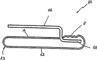
织物管33接着通过如图6所示的第一偏转工作台,并且大致用参考数字64表示。偏转臂66有一个自由端部分68,它的形状使之能够插入折边B下面,并将折边B和与之成重叠关系的折边A分开。尽管在图6或下面的图中未示出,但本领域的技术人员也会理解,本发明的设备包括一个适当的细长平台或板,用于在整个装配过程的连续步骤中支撑织物管33的底面62。The
接着,织物管33通过如图7所示的盘条插入工作台,并且大致用参考数字70表示。一个用72表示的盘条插入装置包括上板74和下板76,这两个板相互平行并且间隔约3/8英寸。上板74有一个可让盘簧16通过的圆形开口78,以使弹簧16由下板76支撑并使其纵轴为垂直方向。应当指出,弹簧16是由任何一种运输机构(未示出)以未压缩状态输送到插入器72的,并且位于压缩器80下方,该压缩器与上板74的开口78垂直对正。此时织物管33的状态是,折边B在插入器72下板76的下面通过,而折边A在支撑板82的下面通过,而且其边缘84由插入器72的上板74支撑。折边A的边缘84由张紧导辊86紧紧地压在板74上。Next, the
在图8中,由于压缩器80的动作而使得弹簧16处于压缩状态。图9表示的是盘条插入过程的下一个步骤,其中织物管33前进的方式是折边A的边缘84进入与气压缸88对齐状态。盘条的插入是在图10中完成的,该图表示的是当往复式空气驱动插杆92从压缩器80处平行地将压缩盘条16移至折边A下的位置时,气压缸88的顶杆90将折边A的边缘84紧紧地压到插入器上板74上。In FIG. 8 , the
盘条的插入完成后,织物管33连同支撑板82下面的压缩盘条16一起被送到大致用图11中数字94表示的第二偏转工作台。在这个工作台94上,第二偏转臂96有一个自由端部98,该端部与折边B接触并将其抬升至原来与折边A搭接的位置。After the insertion of the wire rod is complete, the
图12所示的设备100用来实现本发明过程中的下一步,其中织物管33送到平台102上。平台102可由板82支撑,并且包括一个折边B可从其上面通过的第一上臂104。折边B由张紧导辊106紧紧地压到臂104上。在这一步中,折边A从下面通过第一平台臂104,并位于第二下臂108的上部,该臂是从第一臂104悬挂下来的。平台102的设计使得下臂108也可从上臂104的下部在设备中沿水平方向伸出。The apparatus 100 shown in FIG. 12 is used to carry out the next step in the process of the present invention in which the
现参看图13,第一焊接工作台大致用参考数字110表示,并且包括一个超声波点焊头112。在这个工作台110上,织物管33已经通过了平台102的上臂104,随后折边B又与折边A搭接,两折边都由平台102的下臂108支撑。接着开启焊头112,从而在折边A和折边B之间的搭接部分进行点焊,这就形成了一个搭接焊缝。Referring now to FIG. 13 , a first welding station is indicated generally by the reference numeral 110 and includes an ultrasonic spot welding head 112 . On this table 110 , the
在图14中,第二焊接工作台大致用参考数字114表示,并且包括一个与织物管33横向对准的第二焊头116。在一种本领域熟知的方式中,第二焊头116用于在织物管33的上下侧面之间形成一直线系列的相间焊缝,来分开连续的盘条16,从而形成一列14独立的织物袋18,在每个袋中都装有单独的盘簧16。In FIG. 14 , the second welding station is indicated generally by the reference numeral 114 and includes a second welding head 116 aligned laterally with the
图15大略示出了设备的驱动工作台120,该工作台包括一对紧密平行相间的导辊122和124。导辊122和124被张紧,从而能拉着织物管33从输入工作台30开始通过设备的所有后续工作台。在导辊122或124的其中一个上形成一个适当的凹槽126,从而使盘簧16可在导辊122和124之间自由通过。Figure 15 schematically shows the drive table 120 of the apparatus, which table includes a pair of closely spaced parallel guide rollers 122 and 124 . The guide rollers 122 and 124 are tensioned so as to pull the
图16大略示出了最终成型工作台,并且大致用参考数字130表示。在这个工作台130上,设置一个带有弹性臂134的旋转拍打装置132,用来击打织物管33中的封装盘簧16部分。这个拍打器132的击打动作使盘簧16在袋中旋转90度,并且由压缩状态伸展到舒张状态,从而填充织物袋18。The final forming station is schematically shown in FIG. 16 and generally indicated by the reference numeral 130 . On this table 130, a rotating beating device 132 with an elastic arm 134 is provided for beating the portion of the encased
现在应当清楚,本发明的设备对于形成封装弹簧列来说是高效而实用的,其中弹簧列沿其侧面有一行焊缝,而不是挨着弹簧的端部有一行焊缝。图17以侧视图表示出了采用本设备生产的一列织物封装的盘簧136。如图中所示,一个平的重叠侧缝138代替了图2所示现有技术设计的列14的两个上边28。这样,在一个床垫的内弹簧装置中就很有必要使用盘簧136,因为它可以消除有害的错松。还应理解,由于侧缝138可能只重叠约半英寸左右,与现有技术中具有两个多余边28的情况相比,可节省织物32。进一步讲,本发明的设备可以很容易地在现有设备基础上添加或更换一些部件和配件来制成。相应地,本发明使之能成为对现有设备的更经济的一种改型。It should now be clear that the apparatus of the present invention is efficient and practical for forming encapsulated spring columns having a row of welds along its sides rather than next to the ends of the springs. Figure 17 shows in side view an array of fabric-encased coil springs 136 produced using the apparatus. As shown, a flat
尽管本发明用优选实施方案进行描述,但应当理解,本领域技术人员对设备进行的一些改动和修正并没有脱离本发明的本质精神和范围。因此,附带的权利要求意在涉及所有这些属于本发明本质精神和范围内的改动和修正。Although the present invention has been described in terms of preferred embodiments, it should be understood that changes and modifications of equipment may be made by those skilled in the art without departing from the true spirit and scope of the present invention. Accordingly, the appended claims are intended to cover all such changes and modifications as fall within the true spirit and scope of this invention.
Claims (6)
Applications Claiming Priority (3)
| Application Number | Priority Date | Filing Date | Title |
|---|---|---|---|
| US08/478,915 US5613287A (en) | 1995-06-07 | 1995-06-07 | Method for forming strings of pocketed springs |
| US08/478,915 | 1995-06-07 | ||
| PCT/US1996/009700 WO1996040557A1 (en) | 1995-06-07 | 1996-06-06 | Method and apparatus for forming strings of pocketed springs |
Publications (2)
| Publication Number | Publication Date |
|---|---|
| CN1192722A CN1192722A (en) | 1998-09-09 |
| CN1088024C true CN1088024C (en) | 2002-07-24 |
Family
ID=23901898
Family Applications (1)
| Application Number | Title | Priority Date | Filing Date |
|---|---|---|---|
| CN96196143A Expired - Lifetime CN1088024C (en) | 1995-06-06 | 1996-06-07 | Method and apparatus for forming strings of pocketed springs |
Country Status (21)
| Country | Link |
|---|---|
| US (1) | US5613287A (en) |
| EP (1) | EP0833772B1 (en) |
| JP (1) | JP2983641B2 (en) |
| KR (1) | KR100231386B1 (en) |
| CN (1) | CN1088024C (en) |
| AT (1) | ATE208724T1 (en) |
| AU (1) | AU689724B2 (en) |
| BR (1) | BR9609004A (en) |
| CA (1) | CA2223799C (en) |
| DE (1) | DE69617013T2 (en) |
| DK (1) | DK0833772T3 (en) |
| ES (1) | ES2168482T3 (en) |
| IL (1) | IL122402A (en) |
| IN (1) | IN190816B (en) |
| MY (1) | MY116528A (en) |
| PL (1) | PL181753B1 (en) |
| PT (1) | PT833772E (en) |
| RU (1) | RU2144490C1 (en) |
| TW (1) | TW360510B (en) |
| UA (1) | UA49839C2 (en) |
| WO (1) | WO1996040557A1 (en) |
Families Citing this family (35)
| Publication number | Priority date | Publication date | Assignee | Title |
|---|---|---|---|---|
| SE504366C2 (en) * | 1995-05-08 | 1997-01-20 | Dux Ind Ab | Way and machine to provide a spring mattress path |
| US5749133A (en) | 1996-09-10 | 1998-05-12 | Simmons Company | Method and apparatus for forming strings of pocketed springs |
| US6101697A (en) * | 1997-09-10 | 2000-08-15 | International Bedding Corporation, Inc. | Apparatus for producing string of pocket coils |
| JP2000015377A (en) * | 1998-06-26 | 2000-01-18 | Matsushita Kogyo Kk | Apparatus for manufacturing housing type coil spring |
| US6021627A (en) * | 1998-08-24 | 2000-02-08 | L & P Property Management Company | Manufacture of pocketed compound nested coil springs |
| EP1105660A1 (en) | 1998-08-25 | 2001-06-13 | L & P Property Management Company | Manufacture of pocketed compound nested coil springs |
| US6834477B2 (en) * | 1999-04-16 | 2004-12-28 | Spuhl Ag | Method and system for forming strings of pocketed coil springs with traction mechanism |
| US6591436B2 (en) * | 1999-04-16 | 2003-07-15 | Spuhl Ag St. Gallen | Side seam pocketed coil springs |
| US6336305B1 (en) | 1999-04-16 | 2002-01-08 | Spuhl Ag St. Gallen | System for forming strings of pocketed coil springs |
| US6499275B1 (en) | 1999-04-16 | 2002-12-31 | Spuhl Ag St. Gallen | Method and system for forming strings of pocketed coil springs |
| JP4377074B2 (en) | 1999-04-16 | 2009-12-02 | シュプール アクチェンゲゼルシャフト サンクト ガレン | Method and system for forming a string of pocket coil springs |
| US6260331B1 (en) | 1999-06-17 | 2001-07-17 | Sidhil Technology, Llc | Method and apparatus for the manufacture of pocketed springs |
| US6131892A (en) | 1999-07-06 | 2000-10-17 | Sidhil Technology, Llc | Belted pocketed springs and assemblies thereof |
| US6256820B1 (en) | 2000-02-09 | 2001-07-10 | L&P Property Management Company | Multilayered pocketed bedding or seating product |
| US6718726B1 (en) | 2001-10-09 | 2004-04-13 | Dreamwell Ltd. | Method and apparatus for storing and transporting strings of pocketed coils |
| KR100991459B1 (en) * | 2008-06-16 | 2010-11-04 | 탑와이어 주식회사 | Bookbinding Spring Packaging Device |
| KR100940832B1 (en) * | 2009-07-31 | 2010-02-04 | 주식회사지엠피 | Packing method of document bookbinding binder ring and packing structure |
| PL2565152T3 (en) * | 2011-08-30 | 2014-11-28 | Spuehl Ag | Device for forming a hose out of pocket material and method for producing a pocket row of springs |
| CN105007780B (en) | 2013-01-19 | 2018-11-30 | 马丁·沃尔夫森 | Non-glue bagged spring unit structure |
| EP2813463A1 (en) * | 2013-06-14 | 2014-12-17 | Spühl AG | Apparatus and method for forming a string of pocket springs |
| WO2016118833A1 (en) | 2015-01-23 | 2016-07-28 | Dreamwell, Ltd. | Mattress manufacturing process and apparatus |
| CA2974523C (en) | 2015-01-23 | 2023-12-12 | Dreamwell, Ltd. | Mattress manufacturing process and apparatus |
| US9862553B2 (en) | 2015-01-23 | 2018-01-09 | Dreamwell, Ltd. | Mattress manufacturing process and apparatus |
| WO2016118834A1 (en) | 2015-01-23 | 2016-07-28 | Dreamwell, Ltd. | Mattress manufacturing process and apparatus |
| CA2917406C (en) | 2015-01-23 | 2023-05-09 | Francis G. Jan | Staging cart for transporting mattresses |
| US10365638B2 (en) | 2015-01-23 | 2019-07-30 | Dreamwell, Ltd. | Scheduling process for automated mattress manufacturing |
| TR201902234T4 (en) | 2015-01-23 | 2019-03-21 | Dreamwell Ltd | Mattress production process and apparatus. |
| CA2974529C (en) | 2015-01-23 | 2023-08-15 | Dreamwell, Ltd. | Automated mattress manufacturing process and apparatus |
| US10696540B2 (en) | 2015-04-15 | 2020-06-30 | Dreamwell, Ltd. | Coil string staging area apparatus and method |
| CN105000528B (en) * | 2015-08-18 | 2017-04-26 | 佛山市昱纶机械有限公司 | Film-covered welding pull-down device applied to bag spring machine |
| CN105174193A (en) * | 2015-10-19 | 2015-12-23 | 安吉县龙威家具有限责任公司 | Packaged spring machine |
| CN105174192A (en) * | 2015-10-19 | 2015-12-23 | 安吉县龙威家具有限责任公司 | Packaged spring machine and packaged spring production method |
| EP3202505A1 (en) * | 2016-02-02 | 2017-08-09 | Spühl GmbH | Spring setting device, apparatus for forming a string of pocket springs, and method of setting springs |
| US10874222B2 (en) | 2017-09-22 | 2020-12-29 | Ashley Furniture Industries, Inc. | Ready to assemble furniture |
| ES2978585T3 (en) | 2019-05-14 | 2024-09-16 | Bekaert Sa Nv | Pocket spring coil |
Citations (2)
| Publication number | Priority date | Publication date | Assignee | Title |
|---|---|---|---|---|
| US2093531A (en) * | 1936-07-11 | 1937-09-21 | Murray Corp | Spring covering apparatus |
| CN1061758A (en) * | 1990-12-01 | 1992-06-10 | 斯拉姆伯兰德公共有限公司 | The spring installation assembling |
Family Cites Families (8)
| Publication number | Priority date | Publication date | Assignee | Title |
|---|---|---|---|---|
| US1950186A (en) * | 1931-03-18 | 1934-03-06 | Karpen & Bros S | Coil spring inserting machine |
| US2647671A (en) * | 1947-12-15 | 1953-08-04 | James L Mcinerney | Spring loading machine |
| US3668816A (en) * | 1970-07-10 | 1972-06-13 | Mildred B Thompson | Method and apparatus for constructing fabric enclosed springs |
| US4439977A (en) * | 1977-05-05 | 1984-04-03 | Simmons U.S.A. Corporation | Method and apparatus for making a series of pocketed coil springs |
| US4234983A (en) * | 1978-10-02 | 1980-11-25 | Simmons Company | Thermally welded spring pockets |
| US4854023A (en) * | 1988-06-13 | 1989-08-08 | Simmons U.S.A. Corporation | Method for providing pocketed coil strings having a flat overlap side seam |
| US4986518A (en) * | 1988-06-13 | 1991-01-22 | Simmons U.S.A. Corporation | Pocketed coil strings having a flat overlap side seam |
| JP2836877B2 (en) * | 1988-08-05 | 1998-12-14 | スランバーランド・ホールディングス・リミテッド | Spring unit for mattress etc. |
-
1995
- 1995-06-07 US US08/478,915 patent/US5613287A/en not_active Expired - Lifetime
-
1996
- 1996-06-06 IL IL12240296A patent/IL122402A/en not_active IP Right Cessation
- 1996-06-06 UA UA98010038A patent/UA49839C2/en unknown
- 1996-06-06 AT AT96918383T patent/ATE208724T1/en active
- 1996-06-06 KR KR1019970708896A patent/KR100231386B1/en not_active Expired - Lifetime
- 1996-06-06 BR BR9609004A patent/BR9609004A/en not_active IP Right Cessation
- 1996-06-06 MY MYPI96002289A patent/MY116528A/en unknown
- 1996-06-06 RU RU98100095A patent/RU2144490C1/en active
- 1996-06-06 DK DK96918383T patent/DK0833772T3/en active
- 1996-06-06 PL PL96323733A patent/PL181753B1/en unknown
- 1996-06-06 JP JP9501957A patent/JP2983641B2/en not_active Expired - Lifetime
- 1996-06-06 AU AU61061/96A patent/AU689724B2/en not_active Ceased
- 1996-06-06 EP EP96918383A patent/EP0833772B1/en not_active Expired - Lifetime
- 1996-06-06 ES ES96918383T patent/ES2168482T3/en not_active Expired - Lifetime
- 1996-06-06 WO PCT/US1996/009700 patent/WO1996040557A1/en not_active Ceased
- 1996-06-06 PT PT96918383T patent/PT833772E/en unknown
- 1996-06-06 DE DE69617013T patent/DE69617013T2/en not_active Expired - Lifetime
- 1996-06-06 CA CA002223799A patent/CA2223799C/en not_active Expired - Lifetime
- 1996-06-07 CN CN96196143A patent/CN1088024C/en not_active Expired - Lifetime
- 1996-06-07 IN IN1244DE1996 patent/IN190816B/en unknown
- 1996-06-15 TW TW085107258A patent/TW360510B/en not_active IP Right Cessation
Patent Citations (2)
| Publication number | Priority date | Publication date | Assignee | Title |
|---|---|---|---|---|
| US2093531A (en) * | 1936-07-11 | 1937-09-21 | Murray Corp | Spring covering apparatus |
| CN1061758A (en) * | 1990-12-01 | 1992-06-10 | 斯拉姆伯兰德公共有限公司 | The spring installation assembling |
Also Published As
| Publication number | Publication date |
|---|---|
| KR100231386B1 (en) | 1999-11-15 |
| KR19990022416A (en) | 1999-03-25 |
| RU2144490C1 (en) | 2000-01-20 |
| IL122402A (en) | 2000-11-21 |
| IN190816B (en) | 2003-08-23 |
| DK0833772T3 (en) | 2002-01-21 |
| ES2168482T3 (en) | 2002-06-16 |
| EP0833772A4 (en) | 1999-05-26 |
| CA2223799A1 (en) | 1996-12-19 |
| PL181753B1 (en) | 2001-09-28 |
| DE69617013T2 (en) | 2002-06-13 |
| EP0833772B1 (en) | 2001-11-14 |
| UA49839C2 (en) | 2002-10-15 |
| MY116528A (en) | 2004-02-28 |
| MX9709661A (en) | 1998-10-31 |
| IL122402A0 (en) | 1998-06-15 |
| JP2983641B2 (en) | 1999-11-29 |
| HK1010180A1 (en) | 1999-06-17 |
| PT833772E (en) | 2002-03-28 |
| US5613287A (en) | 1997-03-25 |
| TW360510B (en) | 1999-06-11 |
| AU6106196A (en) | 1996-12-30 |
| AU689724B2 (en) | 1998-04-02 |
| CN1192722A (en) | 1998-09-09 |
| EP0833772A1 (en) | 1998-04-08 |
| ATE208724T1 (en) | 2001-11-15 |
| WO1996040557A1 (en) | 1996-12-19 |
| CA2223799C (en) | 2001-10-30 |
| JPH10507957A (en) | 1998-08-04 |
| PL323733A1 (en) | 1998-04-14 |
| DE69617013D1 (en) | 2001-12-20 |
| BR9609004A (en) | 1999-06-29 |
Similar Documents
| Publication | Publication Date | Title |
|---|---|---|
| CN1088024C (en) | Method and apparatus for forming strings of pocketed springs | |
| EP0928283B1 (en) | Method and apparatus for forming pocketed springs | |
| US6131892A (en) | Belted pocketed springs and assemblies thereof | |
| US10722044B2 (en) | Dual-layered fabric for use in pocketed spring assembly | |
| EP1171377B1 (en) | Method and system for forming strings of pocketed coil springs | |
| WO2001098151A1 (en) | Method and system for forming strings of pocketed coil springs | |
| AU729575B2 (en) | Spring units for mattresses and the like | |
| HK1019871B (en) | Method and apparatus for forming pocketed springs | |
| HK1010180B (en) | Method for forming strings of pocketed springs | |
| MXPA97009661A (en) | Method and apparatus for forming resort chains embolsa | |
| MXPA99002327A (en) | Method and apparatus for forming pocketed springs |
Legal Events
| Date | Code | Title | Description |
|---|---|---|---|
| C06 | Publication | ||
| PB01 | Publication | ||
| C10 | Entry into substantive examination | ||
| SE01 | Entry into force of request for substantive examination | ||
| C14 | Grant of patent or utility model | ||
| GR01 | Patent grant | ||
| ASS | Succession or assignment of patent right |
Owner name: MENHEL CO., LTD. Free format text: FORMER OWNER: SIMMONS CO. Effective date: 20030110 |
|
| C41 | Transfer of patent application or patent right or utility model | ||
| TR01 | Transfer of patent right |
Effective date of registration: 20030110 Address after: Nevada Patentee after: Monwhale Inc. Address before: Georgia, USA Patentee before: Simmons Corp. |
|
| CX01 | Expiry of patent term |
Granted publication date: 20020724 |
|
| EXPY | Termination of patent right or utility model |