CN109069727B - Syringe slot assembly - Google Patents
Syringe slot assembly Download PDFInfo
- Publication number
- CN109069727B CN109069727B CN201780021809.4A CN201780021809A CN109069727B CN 109069727 B CN109069727 B CN 109069727B CN 201780021809 A CN201780021809 A CN 201780021809A CN 109069727 B CN109069727 B CN 109069727B
- Authority
- CN
- China
- Prior art keywords
- plate
- base
- edge
- syringe
- opposing
- Prior art date
- Legal status (The legal status is an assumption and is not a legal conclusion. Google has not performed a legal analysis and makes no representation as to the accuracy of the status listed.)
- Active
Links
Images



Classifications
-
- A—HUMAN NECESSITIES
- A61—MEDICAL OR VETERINARY SCIENCE; HYGIENE
- A61M—DEVICES FOR INTRODUCING MEDIA INTO, OR ONTO, THE BODY; DEVICES FOR TRANSDUCING BODY MEDIA OR FOR TAKING MEDIA FROM THE BODY; DEVICES FOR PRODUCING OR ENDING SLEEP OR STUPOR
- A61M5/00—Devices for bringing media into the body in a subcutaneous, intra-vascular or intramuscular way; Accessories therefor, e.g. filling or cleaning devices, arm-rests
- A61M5/008—Racks for supporting syringes or needles
-
- B—PERFORMING OPERATIONS; TRANSPORTING
- B01—PHYSICAL OR CHEMICAL PROCESSES OR APPARATUS IN GENERAL
- B01L—CHEMICAL OR PHYSICAL LABORATORY APPARATUS FOR GENERAL USE
- B01L9/00—Supporting devices; Holding devices
- B01L9/54—Supports specially adapted for pipettes and burettes
-
- B—PERFORMING OPERATIONS; TRANSPORTING
- B32—LAYERED PRODUCTS
- B32B—LAYERED PRODUCTS, i.e. PRODUCTS BUILT-UP OF STRATA OF FLAT OR NON-FLAT, e.g. CELLULAR OR HONEYCOMB, FORM
- B32B27/00—Layered products comprising a layer of synthetic resin
- B32B27/06—Layered products comprising a layer of synthetic resin as the main or only constituent of a layer, which is next to another layer of the same or of a different material
-
- B—PERFORMING OPERATIONS; TRANSPORTING
- B32—LAYERED PRODUCTS
- B32B—LAYERED PRODUCTS, i.e. PRODUCTS BUILT-UP OF STRATA OF FLAT OR NON-FLAT, e.g. CELLULAR OR HONEYCOMB, FORM
- B32B27/00—Layered products comprising a layer of synthetic resin
- B32B27/32—Layered products comprising a layer of synthetic resin comprising polyolefins
-
- B—PERFORMING OPERATIONS; TRANSPORTING
- B32—LAYERED PRODUCTS
- B32B—LAYERED PRODUCTS, i.e. PRODUCTS BUILT-UP OF STRATA OF FLAT OR NON-FLAT, e.g. CELLULAR OR HONEYCOMB, FORM
- B32B3/00—Layered products comprising a layer with external or internal discontinuities or unevennesses, or a layer of non-planar shape; Layered products comprising a layer having particular features of form
- B32B3/10—Layered products comprising a layer with external or internal discontinuities or unevennesses, or a layer of non-planar shape; Layered products comprising a layer having particular features of form characterised by a discontinuous layer, i.e. formed of separate pieces of material
- B32B3/12—Layered products comprising a layer with external or internal discontinuities or unevennesses, or a layer of non-planar shape; Layered products comprising a layer having particular features of form characterised by a discontinuous layer, i.e. formed of separate pieces of material characterised by a layer of regularly- arranged cells, e.g. a honeycomb structure
-
- B—PERFORMING OPERATIONS; TRANSPORTING
- B32—LAYERED PRODUCTS
- B32B—LAYERED PRODUCTS, i.e. PRODUCTS BUILT-UP OF STRATA OF FLAT OR NON-FLAT, e.g. CELLULAR OR HONEYCOMB, FORM
- B32B3/00—Layered products comprising a layer with external or internal discontinuities or unevennesses, or a layer of non-planar shape; Layered products comprising a layer having particular features of form
- B32B3/26—Layered products comprising a layer with external or internal discontinuities or unevennesses, or a layer of non-planar shape; Layered products comprising a layer having particular features of form characterised by a particular shape of the outline of the cross-section of a continuous layer; characterised by a layer with cavities or internal voids ; characterised by an apertured layer
- B32B3/30—Layered products comprising a layer with external or internal discontinuities or unevennesses, or a layer of non-planar shape; Layered products comprising a layer having particular features of form characterised by a particular shape of the outline of the cross-section of a continuous layer; characterised by a layer with cavities or internal voids ; characterised by an apertured layer characterised by a layer formed with recesses or projections, e.g. hollows, grooves, protuberances, ribs
-
- B—PERFORMING OPERATIONS; TRANSPORTING
- B32—LAYERED PRODUCTS
- B32B—LAYERED PRODUCTS, i.e. PRODUCTS BUILT-UP OF STRATA OF FLAT OR NON-FLAT, e.g. CELLULAR OR HONEYCOMB, FORM
- B32B7/00—Layered products characterised by the relation between layers; Layered products characterised by the relative orientation of features between layers, or by the relative values of a measurable parameter between layers, i.e. products comprising layers having different physical, chemical or physicochemical properties; Layered products characterised by the interconnection of layers
- B32B7/04—Interconnection of layers
- B32B7/08—Interconnection of layers by mechanical means
-
- B—PERFORMING OPERATIONS; TRANSPORTING
- B65—CONVEYING; PACKING; STORING; HANDLING THIN OR FILAMENTARY MATERIAL
- B65D—CONTAINERS FOR STORAGE OR TRANSPORT OF ARTICLES OR MATERIALS, e.g. BAGS, BARRELS, BOTTLES, BOXES, CANS, CARTONS, CRATES, DRUMS, JARS, TANKS, HOPPERS, FORWARDING CONTAINERS; ACCESSORIES, CLOSURES, OR FITTINGS THEREFOR; PACKAGING ELEMENTS; PACKAGES
- B65D25/00—Details of other kinds or types of rigid or semi-rigid containers
- B65D25/02—Internal fittings
- B65D25/10—Devices to locate articles in containers
- B65D25/108—Devices, e.g. plates, presenting apertures through which the articles project
-
- B—PERFORMING OPERATIONS; TRANSPORTING
- B32—LAYERED PRODUCTS
- B32B—LAYERED PRODUCTS, i.e. PRODUCTS BUILT-UP OF STRATA OF FLAT OR NON-FLAT, e.g. CELLULAR OR HONEYCOMB, FORM
- B32B2250/00—Layers arrangement
- B32B2250/02—2 layers
-
- B—PERFORMING OPERATIONS; TRANSPORTING
- B32—LAYERED PRODUCTS
- B32B—LAYERED PRODUCTS, i.e. PRODUCTS BUILT-UP OF STRATA OF FLAT OR NON-FLAT, e.g. CELLULAR OR HONEYCOMB, FORM
- B32B2274/00—Thermoplastic elastomer material
-
- B—PERFORMING OPERATIONS; TRANSPORTING
- B32—LAYERED PRODUCTS
- B32B—LAYERED PRODUCTS, i.e. PRODUCTS BUILT-UP OF STRATA OF FLAT OR NON-FLAT, e.g. CELLULAR OR HONEYCOMB, FORM
- B32B2535/00—Medical equipment, e.g. bandage, prostheses or catheter
Landscapes
- Health & Medical Sciences (AREA)
- Engineering & Computer Science (AREA)
- Mechanical Engineering (AREA)
- Life Sciences & Earth Sciences (AREA)
- General Health & Medical Sciences (AREA)
- Biomedical Technology (AREA)
- Heart & Thoracic Surgery (AREA)
- Hematology (AREA)
- Vascular Medicine (AREA)
- Animal Behavior & Ethology (AREA)
- Anesthesiology (AREA)
- Public Health (AREA)
- Veterinary Medicine (AREA)
- Clinical Laboratory Science (AREA)
- Chemical & Material Sciences (AREA)
- Chemical Kinetics & Catalysis (AREA)
- Infusion, Injection, And Reservoir Apparatuses (AREA)
- Medical Preparation Storing Or Oral Administration Devices (AREA)
Abstract
The injector slot assembly includes a base having a first surface and an opposing second surface and a first plate movably coupled to the base. The base includes a plurality of nested cells extending upwardly away from the first surface of the base. Each nesting unit includes a hollow body having a first open end distal to the first surface of the base and an opposite second open end. The first plate has a first surface and an opposing second surface. The first plate includes a plurality of apertures extending from the first surface to the second surface of the first plate. Each aperture of the first plate is substantially aligned with a respective nesting unit of the base.
Description
Technical Field
The invention relates to an injector slot assembly. In particular, the present invention relates to a syringe slot assembly configured to more accurately center syringes contained therein relative to one another and facilitate proper positioning of the syringes when connected with automated manufacturing, handling, packaging, and filling equipment.
Background
The syringe slot is typically a substantially planar tray that sits within the syringe barrel and has a plurality of individual nesting units, commonly referred to as chimneys, each capable of receiving a syringe to contain, transport, and fill the syringe during various manufacturing processes. Syringe slots are commonly used in automated processes for assembling, for example, pre-filled syringes. The chimney of the injector slot has a defined center-to-center distance that must be maintained accurately to ensure that the slot is compatible with existing manufacturing, packaging and filling equipment. In recent years, the number of injector slots has increased in size, and 160 chimneys/slots may become the new standard.
This allows the injector chimneys to be formed significantly closer together, particularly for slots requiring a larger chimney diameter due to the integrated safety system. However, as the diameter of standard chimneys increases, maintaining the center-to-center distance becomes more difficult, which is necessary to ensure proper engagement of the syringe with existing automated manufacturing, handling, packaging and filling equipment.
Accordingly, there is a need for an injector slot assembly that ensures that the injectors located therein meet the center-to-center distances necessary for the standard.
Disclosure of Invention
Briefly, in one embodiment, the present disclosure is directed to an injector slot assembly that includes a base having a first surface and an opposing second surface and a first plate movably coupled to the base. The base includes a plurality of nested cells extending upwardly away from the first surface of the base. Each nesting unit includes a hollow body having a first open end distal to the first surface of the base and an opposite second open end. The first plate has a first surface and an opposing second surface. The first plate includes a plurality of apertures extending from the first surface to the second surface of the first plate. Each aperture of the first plate is substantially aligned with a respective nesting unit of the base.
In another embodiment, the invention is directed to a method of centering two or more syringes in a syringe slot assembly. The injector slot assembly includes a base having a first surface and an opposing second surface and a first plate movably coupled to the base. The base includes a plurality of nested cells extending upwardly away from the first surface of the base. Each nesting unit includes a hollow body having a first open end distal to the first surface of the base and an opposite second open end. The first plate has a first surface and an opposing second surface. The first plate includes a plurality of apertures extending from the first surface to the second surface of the first plate. Each aperture of the first plate is substantially aligned with a respective nesting unit of the base. The method comprises positioning a first syringe in a first nesting unit and a second syringe in a second nesting unit adjacent to the first nesting unit such that the barrel of each syringe extends through the hollow body of the respective nesting unit; and sliding the first plate in a first direction such that the first plate contacts each syringe and moves each syringe toward the inner wall surface of the respective nested unit until each syringe contacts the inner wall surface of the respective nested unit.
In another embodiment, the invention is directed to an injector slot comprising a flexible base having a first surface and an opposing second surface. The base includes a plurality of nested units extending upwardly away from the first surface of the base. Each nesting unit includes a hollow body having a first open end distal to the first surface of the base and an opposite second end. The base also includes a notch formed at the second end of each nested unit. Each notch is configured to be in a closed position when the syringe is not positioned in the nested unit and each notch is configured to be in an open position when the syringe is positioned in the nested unit such that the syringe extends through the base when the notch is in the open position.
Drawings
The foregoing summary, as well as the following detailed description of preferred embodiments of the present invention, will be better understood when read in conjunction with the appended drawings. For the purpose of illustrating the invention, there is shown in the drawings embodiments which are presently preferred. It should be understood, however, that the invention is not limited to the precise arrangements and instrumentalities shown. In the drawings:
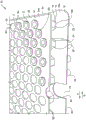
FIG. 1 is a top front perspective view of an injector slot assembly according to an embodiment of the present invention.
FIG. 2A is a top front partial perspective view of the injector slot assembly shown in FIG. 1 with an injector in a first non-centered position;
FIG. 2B is a top front partial perspective view of the injector slot assembly shown in FIG. 1 with an injector in a second centered position;
FIG. 3A is a top front partial perspective view of the injector slot (with the top plate removed) shown in FIG. 1, with the injector in a first non-centered position;
FIG. 3B is a top front partial perspective view of the injector slot assembly shown in FIG. 1 (with the top plate removed) with the injector in a second centered position;
FIG. 4A is a top front perspective view of a syringe slot assembly according to a second embodiment of the present invention, wherein the assembly is shown with a syringe in a first non-centered position;
FIG. 4B is a top front perspective view of the syringe slot assembly shown in FIG. 4A with the syringe in a second centered position;
FIG. 5 is an enlarged top side partial perspective view of the injector port assembly shown in FIGS. 4A-4B;
FIG. 6A is a front perspective view of the base of a syringe slot assembly according to a third embodiment of the present invention, wherein the assembly is shown in a first position in which the syringes are not centered;
FIG. 6B is a base front perspective view of the injector slot assembly shown in FIG. 6A in a second position in which the injectors will be centered relative to one another;
FIG. 7 is a top partial plan view of an injector slot assembly according to a fourth embodiment of the present invention; and
FIG. 8 is a partial side perspective view of the base of the injector slot assembly shown in FIG. 7.
Detailed Description
Reference will now be made in detail to the present embodiments of the invention, which are illustrated in the accompanying drawings. It should be noted that the drawings are in simplified form and are not drawn to precise scale. Certain terminology is used in the following description for convenience only and is not limiting. The words "right", "left", "top", "bottom" and "lower" designate directions in the drawings to which reference is made. The words "first", "second", "third" and "fourth" denote the order of operation in the referenced figures, but do not limit the steps to the exact order described. The words "inwardly" and "outwardly" refer to directions toward and away from, respectively, the geometric center of the component and designated parts thereof. The terms "a," "an," and "the" are not limited to one element, but rather are to be construed as "at least one," unless specifically stated otherwise herein. The terminology includes the words above, derivatives thereof and words of similar import.
Referring to the drawings in detail, wherein like numerals and characters indicate like elements throughout, there is shown in FIGS. 1-8 a presently preferred embodiment of an injector slot assembly according to the present invention. Referring first to fig. 1-3B, an injector slot assembly, generally designated 10, includes an injector slot 12 and at least one movable plate 14.
Referring to fig. 1, the trough 12 includes a substantially planar base or tray 16, the base or tray 16 having a first surface 16a and an opposing second surface 16 b. The base 16 also includes a first edge or side 40 and an opposing second edge or side 42. The first and second edges 40, 42 extend parallel to each other. The base 16 also includes a third edge or side 44 and an opposite fourth edge or side 46. The third and fourth edges 44, 46 are parallel to each other and extend perpendicular to the first and second edges 40, 42. Longitudinal axis X of base 1616Extending from the third edge 44 parallel to the first and second edges 40, 42 towards the fourth edge 46 (or vice versa).
While the present embodiment is configured with the base 16 configured as a planar rectangular tray, the base 16 may alternatively be configured in any planar manner suitable for its intended use, such as a planar circular, square, oval, or octagonal tray.
The tank 12 also includes a plurality of individual nested units, referred to herein as chimneys 18. Each chimney 18 comprises a substantially hollow body 19 extending distally from the first surface 16a of the base 16. The hollow body 19 includes a first open end 19a distal from the base 16 and a second open end 19b proximal to the base 16. The hollow body 19 also includes an inner wall surface 20 and an outer wall surface 22. The tank 12 may also include an injector 34 housed within each of the plurality of chimneys 18.
Referring to fig. 3A-3B, in one embodiment, each chimney 18 preferably has a hexagonal shape or geometry. Thus, each chimney 18 has six sidewalls 24 and six connecting lines (also referred to as vertices or corners) 26. The hexagonal chimneys 18 are arranged in a honeycomb pattern. By this honeycomb pattern, the chimneys 18 are connected to each other in such a way: at least one side wall 24 of one chimney 18, and preferably each side wall 24, also forms a side wall 24 (i.e., a continuous wall) of another chimney 18 such that no voids are formed between adjacent chimneys 18. Each chimney 18 thus shares at least one sidewall 24 with at least one other chimney 18. More preferably, each sidewall 24 of each chimney 18 is common to each sidewall of another chimney 18, except for the outermost chimney 18. Thus, each chimney 18 shares a common sidewall 24 with a plurality of other chimneys 18.
Traditionally, using only a honeycomb structure based on the required center-to-center distance would require an excessive wall thickness to form a platform on which the flange of the syringe can be placed, which is disadvantageous for injection molding. However, the present invention avoids such excessive wall thickness. In particular, each hexagonal chimney 18 has a relatively large diameter, such that a predetermined center-to-center distance D of the injectors 34 contained therein can be maintained, but without excessive sidewall 24 thickness.
It should be understood, however, that the chimneys 18 need not have a hexagonal geometry and need not be arranged in a honeycomb pattern. In practice, the chimneys 18 may be cylindrical and arranged in any pattern, with or without gaps or voids between adjacent chimneys.
Referring to fig. 3A-3B, in one embodiment, each outermost chimney 18 adjacent the first edge 40 of the base 16 includes a protruding tab, edge, or flange 48 that extends outwardly away from the chimney body 19 toward the first edge 40. More specifically, at the first open end 19a of each peripheral chimney 18 adjacent the first edge 40, a portion of the chimney body 19 includes or is formed as a peripheral flange 48, the peripheral flange 48 projecting outwardly away from the chimney body 19 toward the first edge 40. In the case of the hexagonal chimney 18, a peripheral flange 48 is formed on one side wall 24 at the first open end 19a of the chimney body 19.
In general, the peripheral flange 48 of the outermost chimney 18 adjacent the first edge 40 defines a first longitudinally extending peripheral flange 50 in the plane of the first open end 19a of the chimney body 19 and away from the base 16, and more particularly the first peripheral flange 50 extending along the first edge 40 of the base 16. The first peripheral flange 50 is along the longitudinal axis X16Extending (i.e., from the third edge 44 toward the fourth edge 46, or vice versa). The first peripheral flange 50 includes spaced apart individual flanges 48 adjacent the first edge 40, each flange 48 being along the longitudinal axis X16Extending (i.e., from the third edge 44 toward the fourth edge 46, or vice versa).
Preferably, at the first open end 19a of each outermost chimney 18 adjacent the second edge 42 of the base 16, a portion of the chimney body 19 further includes or is formed as a peripheral projection or flange 48 that projects outwardly from the chimney body 19 toward the second edge 42. That is, the sidewall of each chimney 18 proximate the first and second edges 40, 42 includes a peripheral flange 48. Generally, the peripheral flange 48 of the outermost chimney 18 adjacent the second edge 42 defines a second peripheral flange 50 in the plane of the first open end 19a of the chimney body 19 and away from the base 16, the second peripheral flange 50 extending along the second edge 42 of the base 16. The second peripheral flange 50 is along the longitudinal axis X16(i.e., from the third edge 44 toward the fourth edge 46, or vice versa). Thus, the second peripheral flange 50 is a mirror image of the first peripheral flange 50. The second peripheral flange 50 includes spaced apart individual flanges 48 adjacent the second edge 42, each flange 48 along the longitudinal axis X16Extending (i.e., from the third edge 44 toward the fourth edge 46, or vice versa).
The plate 14 has a substantially planar shape and includes a first surface 14a and an opposing second surface 14 b. In the assembled position of the syringe slot assembly 10, the second surface 14b faces the first surface 16a of the base 16. The plate 14 further comprises a first edge or side 52 and an opposite second edge or side 54. The first and second edges 52, 54 extend parallel to each other. The plate 14 also includes a third edge or side 56 and an opposite fourth edge or side 58. The third and fourth edges 56, 58 are parallel to each other and extend perpendicular to the first and second edges 52, 54. Longitudinal axis X of plate 1414Extending parallel to the first and second edges 52, 54 from the third edge 56 toward the fourth edge 58 (or vice versa).
While the present embodiment is configured with the plate 14, the plate 14 being configured in a planar rectangular form, the plate 14 may alternatively be configured in any planar manner suitable for its intended use, such as a planar circular, square, oval or octagonal shape. Preferably, however, the shape of the plate 14 conforms to the shape of the base 16.
The plate 14 also includes a plurality of spaced apart openings or holes 60, the plurality of spaced apart openings or holes 60 extending from the first surface 14a to the second surface 14 b. The aperture 60 is defined by a sidewall 61, the sidewall 61 extending through the body of the plate 14 from the first surface 14a to the second surface 14 b. Each aperture 60 is positioned (i.e., configured to align) with a respective one of the chimneys 18 of the tank 12. The holes 60 may have any geometric shape. Preferably, the bore 60 is cylindrical (e.g., circular in cross-section). However, it should be understood that the apertures 60 may alternatively be hexagonal or any other shape that is complementary to the shape of the associated chimney 18.
In one embodiment, the first edge 52 of the plate 14 includes a first elongated slot or groove 62, the first elongated slot or groove 62 configured to mate with the first peripheral flange 50 of the base 16 (i.e., the single flange 48 of the peripheral chimney 18). More specifically, the first edge 52 of the plate 14 is provided with an L-shape that extends downwardly from the first edge 52 and defines a first elongated slot 62 therein. The first elongated slot 62 is along the longitudinal axis X of the plate 1414Extending (i.e., from the third edge 56 toward the fourth edge 58, or vice versa). The first peripheral flange 50 of the peripheral chimney 18 of the first edge 40 of the slot 12 is received and movable within the first elongated slot 62. By this engagement, the plate 14 can slide relative to the slot 12, and more specifically relative to the slotThe base 16 and chimney 18 slide.
Preferably, the second edge 54 of the plate 14 includes a second elongated slot or groove 62, the second elongated slot or groove 62 configured to mate with the second peripheral flange 50 of the base 16. More specifically, the second edge 54 of the plate 14 is provided with an L-shape that extends downwardly from the second edge 54 and defines a second elongated slot 62 therein. The second elongated slot 62 is along the longitudinal axis X of the plate 1414Extending (i.e., from the third edge 56 toward the fourth edge 58, or vice versa). The second peripheral flange 50 of the peripheral chimney 18 of the second edge 42 of the slot 12 is received and movable within the second elongated slot 62. By this engagement, the plate 14 is slidable relative to the channel 12, and more specifically relative to the base 16 and chimney 18.
More specifically, plate 14 is slidable with respect to nest 12 in a first direction a or in an opposite second direction B, the first and second directions being parallel to the longitudinal axis X of plate 14 and base 16, respectively14、X16. As described in further detail below, by this sliding motion, the plate 14 may move the injectors 34 so as to maintain a predetermined center-to-center distance D (e.g., according to manufacturer requirements) between the injectors 34 placed within each chimney 18 (see fig. 2B and 3B). The predetermined center-to-center distance D refers to the distance between the center C of an injector 34 disposed in one chimney 18 and the center C of an injector 34 disposed in an adjacent chimney 18.
Those skilled in the art will appreciate that the first and second peripheral flanges 50 of the base 16 need not be formed along the first and second edges 40, 42 of the base 16, and the respective first and second elongated slots 62 need not be formed along the first and second edges 52, 54 of the plate 14. Rather, flanges and slots may be formed along the third and fourth edges 44, 46 and 56, 58 of the base 16 and the plate 14 such that the plate 14 is slidable in a third or fourth direction perpendicular to the first and second directions A, B (i.e., perpendicular to the longitudinal axis X of the plate 14 and the base 16, respectively)14、X16Direction of (d). Alternatively, the flanges may be formed adjacent to certain edges 52, 54, 56, 58 of the panel 14, while the slots are formed adjacent to the corresponding edges 40, 42 of the base 1644, 46.
In a first assembled position of injector slot assembly 10, as shown in fig. 2A, plate 14 is connected to slot 12 such that first and second peripheral flanges 50 of base 16 are received within first and second elongated slots 62 of plate 14. Thus, the plate 14 and base 16 may be oriented along the longitudinal axis X14、X16Move, more particularly are slidable, relative to each other. The injectors 34 are located within one or more of the apertures 60 and corresponding chimneys 18 of the assembly 10. However, the syringes 34 are not properly centered, meaning that they are not positioned to maintain a predetermined center-to-center distance D between adjacent syringes 34.
In one embodiment, in the assembled position, the flange 64 of each injector 34 is positioned above the plane of the plate 14, and the barrel 66 of each injector 34 is positioned within the aperture 60 of the plate 14 and the corresponding chimney 18 of the slot 12 (and extends through the aperture 60 and the chimney 18). The flange 64 of each syringe 34 may rest on the first surface 14a of the plate 14 or may be adjacent to the first surface 14a but not in contact with the first surface 14 a.
In another embodiment, in the assembled position, the flange 64 of each injector 34 is positioned within the bore 60 of the plate 14 (e.g., within a counterbore) and the barrel 66 of each injector is positioned within the respective chimney 18 of the nest 12 (and extends through the chimney 18).
To place the injector slot assembly 10 in the second position, wherein the injectors 34 are at the predetermined center-to-center distance D, the plate 14 is moved, and more specifically, along the longitudinal axis X14Sliding in a first direction a. The sliding of plate 14 causes the inner side wall 61 of aperture 60 of plate 14 to contact the barrel 66 or flange 64 of syringe 34 located therein. By this contact, the plate 14 moves the injector 34 together with the plate 14 in the first direction a toward the inner wall surface 20 of the corresponding chimney 18. The sliding movement of the plate 14 and the injectors 34 continues until the barrel 66 of each injector 34 abuts or contacts a portion of the inner wall surface 20 of the chimney 18 in which the injector 34 is positioned (see fig. 2B and 3B). Thus, a second position of the injector slot assembly 10 is reached, as shown in fig. 2B and 3B, wherein the injectors 34 are positioned according to the necessary center-to-center distance D。
Fig. 4A-5 depict another embodiment of a syringe reservoir assembly 100 according to the present invention. The injector slot assembly 100 is substantially similar to the injector slot assembly 10 of fig. 1-3B, except for certain aspects discussed below.
Referring to fig. 4A-4B, the injector slot assembly 100 includes an injector slot 102 and at least one movable plate 104. The trough 102 includes a substantially planar base or tray 106 having a first surface 106a and an opposing second surface 106 b. The base 106 also includes a first edge or side 140 and an opposing second edge or side 142. The first and second edges 140, 142 extend parallel to each other. The base 106 also includes a third edge or side 144 and an opposing fourth edge or side 146. The third and fourth edges 144, 146 are parallel to each other and extend perpendicular to the first and second edges 140, 142. Longitudinal axis X of base 106106Extending parallel to the first and second edges 140, 142 from the third edge 144 toward the fourth edge 146 (or vice versa).
The base 16 is preferably configured as a planar rectangular tray, but may alternatively be configured in any planar manner suitable for its intended use, such as a planar circular, square, oval or octagonal tray.
The trough 102 also includes a plurality of chimneys 108, and more preferably, a plurality of spaced chimneys 108 (i.e., there are gaps between adjacent chimneys 108). However, it should be understood that the chimneys 108 may be arranged in any pattern, such as, for example, the honeycomb pattern described with reference to fig. 1-3B.
Each chimney 108 includes a substantially hollow body 109 that extends distally from the first surface 106a of the base 106. The hollow body 109 includes a first open end 109a distal from the base 106 and a second open end 109b proximal to the base 16. The hollow body 109 also includes an inner wall surface 120 and an outer wall surface 122. The tank 102 may also include an injector 134 housed within each of the plurality of chimneys 108.
Referring to fig. 4A-5, in one embodiment, each chimney 108 preferably has a cylindrical shape or geometry. However, it should be understood that the chimney 108 may have any suitable shape or geometry, such as, for example, the hexagonal geometry discussed above with reference to fig. 1-3B.
4A-5, in one embodiment, the base 106 includes a first elongated slot 162 formed adjacent to or at the first edge 140. The first elongated slot 162 is preferably along the longitudinal axis X of the base 106106Extending (i.e., from adjacent the third edge 144 toward the fourth edge 146, or vice versa). The base 106 also preferably includes a second elongated slot 162 formed adjacent to or at the second edge 142, similarly along the longitudinal axis X of the base 106106And (4) extending.
The plate 104 has a substantially planar shape and includes a first surface 104a and an opposing second surface 104 b. In the assembled position of the syringe slot assembly 100, the second surface 104b faces the first surface 106a of the base 106. The plate 104 also includes a first edge or side 152 and an opposing second edge or side 154. The first and second edges 152, 154 extend parallel to each other. The plate 104 also includes a third edge or side 156 and an opposite fourth edge or side 158. The third and fourth edges 156, 158 extend parallel to each other and perpendicular to the first and second edges 152, 154. Longitudinal axis X of plate 104104Extending parallel to the first and second edges 152, 154 from the third edge 156 toward the fourth edge 158 (or vice versa).
While the plate 104 is preferably configured in a planar rectangular form, the plate 104 may alternatively be configured in any planar form suitable for its intended use, such as a planar circular, square, oval, or octagonal shape. Preferably, however, the shape of the plate 104 conforms to the shape of the base 106.
The plate 104 also includes a central raised portion 105. The central raised portion 105 has a distal surface 105a that extends in a plane above the plane of the first surface 104a of the plate 104. The plate 104 also includes a plurality of openings or holes 160 extending through the body of the plate 104, and more specifically, a plurality of openings or holes 160 extending from the distal surface 105a of the raised portion 105 to the second surface 104b of the plate 104. The aperture 160 is defined by a sidewall 161, the sidewall 161 extending through the body of the plate 104, and more particularly, from the distal surface 105a of the raised portion 105 to the second surface 104b of the plate 104. Each aperture 160 is positioned to correspond with (i.e., align with) a respective one of the chimneys 108 of the slot 102. The aperture 160 may have any geometry. Preferably, the bore 160 is cylindrical (e.g., circular in cross-section). However, it should be understood that the apertures 160 may alternatively be hexagonal or any other shape that is complementary to the shape of the associated chimney 108.
The plate 104 also preferably includes at least one post 112, and more preferably a plurality of spaced apart posts 112. More specifically, a plurality of spaced-apart posts 112 are preferably formed or otherwise disposed adjacent to or at the first edge 152 of the plate 104. Preferably, a plurality of spaced-apart posts 112 are also formed or otherwise disposed adjacent to or at the second edge 154 of the plate 104.
Each post 112 has a first proximal end 112a and an opposite second distal end 112 a. The first proximal end 112a is preferably attached to the plate 104 or integrally formed with the plate 104, and more preferably attached to the second surface 104b of the plate 104 or integrally formed with said second surface 104 b. The distal end 112a of each post 112 is distal from the plate 104. Thus, each post 112 is a downwardly facing post. Those skilled in the art will appreciate that the term "post" is used herein for illustrative purposes only, and may be readily replaced by another suitable term, such as a pin, tab, protrusion, rod, etc.
Referring to fig. 5, the distal end 112a of each post 112 is preferably movably coupled to the base 106, and more specifically, to one of the elongated slots 162 of the base 106. More specifically, the distal end 112a of each post 112 includes first and second tongues 114. The first tongue 114 projects outwardly away from the body of the post 112 in a first direction, while the second tongue 114 projects outwardly away from the body of the post 112 in a second direction opposite the first direction. Each post 112 formed adjacent the first edge 152 of the plate 104, and more specifically the distal end 112a of each post 112, is configured to mate with the first elongated slot 162 of the base 106. Each post 112 formed adjacent the second edge 154 of the plate 104, and more particularly, the distal end 112a of each post 112, is configured to mate with the second elongated slot 162 of the base 106. More specifically, in the mated configuration, distal end 112a of each post 112 engages one of the elongated slots 162 such that one of first and second tongues 114 extends toward first edge 140 of base 106 and engages first surface 106a of base 106, and the other of first and second tongues 114 extends away from first edge 140 of base 106 and engages second surface 106b of base 106.
Thus, the posts 112 of the plate 104 are received and moved within the first and second elongated slots 162 of the base 106. Through this engagement, the plate 104 is slidable relative to the slot 102, and more specifically relative to the base 106 and chimney 108. More specifically, plate 104 is slidable relative to nest 102 in a first direction a or an opposite second direction B, the first and second directions being parallel to longitudinal axis X of plate 104 and base 106, respectively104、X106。
Those skilled in the art will appreciate that the first and second elongated slots 162 of the base 106 need not be formed along the first and second edges 140, 142 of the base 106, and the respective posts 112 of the plate 104 need not be formed along the first and second edges 152, 154 of the plate 104. Instead, slots and posts may be formed along the third and fourth edges 144, 146 and 156, 158 of the base 106 and the plate 104 such that the plate 104 is slidable in a third or fourth direction perpendicular to the first and second directions a, B (i.e., perpendicular to the longitudinal axis X of the plate 104 and the base 106, respectively)104、X106Direction of (d).
In a first set of device positions of injector slot assembly 100, as shown in fig. 4A, plate 104 is coupled to nest 102 such that distal ends 112a of posts 112 of plate 104 are received within first and second elongated slots 162 of base 106. In this way, the plate 104 and the base 106 may be along the longitudinal axis X104、X106Move relative to each other and, more particularly, are slidable. The injector 134 is located within one or more of the aperture 160 and the corresponding chimney 108 of the assembly 100. However, the syringes 134 are not properly centered, meaning that they are not positioned so as to maintain a predetermined center-to-center distance D between adjacent syringes 134.
In one embodiment, in the assembled position, the flange 164 of each injector 134 is positioned within the aperture 160 of the plate 104, and the barrel 166 of each injector 134 is positioned within (and extends through) the respective chimney 108 of the slot 102. Each hole 160 includes counterbores that capture the syringe flange 164 therein on the top and bottom sides of the flange 164, which allows for better control of the deflection of the syringe 134.
In another embodiment (not shown), the flange 164 of each injector 134 is positioned above the plane of the raised portion 105 of the plate 104, and the barrel 166 of each injector 134 is positioned within the aperture 160 of the plate 104 (and extends through the aperture 160 of the plate 104). The flange 164 of each syringe 134 may rest on the distal surface 105a of the raised portion 105 of the plate 104, or may be adjacent to but not in contact with the distal surface 105 a. In another embodiment, the plate 104 does not include the raised portion 105, such that the flange 164 of each injector 134 rests on the first surface 104a of the plate 104 or is proximate to but does not contact the first surface 104 a.
To place the injector slot assembly 100 in the second position shown in FIG. 4B, wherein the injectors 134 are at the predetermined center-to-center distance D, the plate 104 is moved, and more specifically, in the first direction A along the longitudinal axis X104And (4) sliding. The sliding movement of the plate 104 causes the inner side walls 161 of the apertures 160 to contact the flange 164 (or barrel 166) of the syringe 134 located therein. By this contact, the plate 104 moves the injector 134 with the plate 104 in the first direction a toward the inner wall surface 120 of the respective chimney 108. The sliding movement of the plate 104 and the syringes 134 continues until the barrel 166 of each syringe 134 abuts or contacts a portion of the inner wall surface 120 of the chimney 108 in which the syringe 134 is positioned. Thus, as shown in FIG. 4B, a second position of the syringe slot assembly 100 is obtained in which the syringes 134 are positioned according to the requisite center-to-center distance D.
Fig. 6A-6B depict another embodiment of a syringe reservoir assembly 200 according to the present invention. The injector slot assembly 200 is substantially similar to the injector slot assembly 10 of fig. 1-3B, except for certain aspects discussed below.
Referring to fig. 6A-6B, an injector slot assembly 200 includes an injector slot 202 and at least one movable plate 204. More excellentOptionally, the injector slot assembly 200 includes a first movable plate 204 and a second movable plate 280. The well 202 is generally similar to the injector well 102 of fig. 4A-5, except for certain aspects discussed below. The trough 202 includes a substantially planar base or tray 206 having a first surface 206a and an opposing second surface 206 b. The base 206 also includes a first edge or side 240 and an opposing second edge or side 242. The first and second edges 240, 242 extend parallel to each other. The base 206 also includes a third edge or side 244 and an opposing fourth edge or side 246. The third and fourth edges 244, 246 extend parallel to each other and perpendicular to the first and second edges 240, 242. Longitudinal axis X of base 206206Extending parallel to the first and second edges 240, 242 from the third edge 244 toward the fourth edge 246 (or vice versa).
The base 206 is preferably configured as a planar rectangular tray, but may alternatively be configured in any planar manner suitable for its intended use, such as a planar circular, square, oval, or octagonal tray.
The trough 202 also includes a plurality of chimneys 208, and more preferably, a plurality of spaced chimneys 208 (i.e., there are gaps between adjacent chimneys 208). However, it should be understood that the chimneys 208 may be arranged in any pattern, such as, for example, the honeycomb pattern described with reference to fig. 1-3B.
Each chimney 208 comprises a substantially hollow body 209, said body 209 extending distally from the first surface 206a of the base 206. The hollow body 209 includes a first open end 209a distal from the base 206 and a second open end 209b proximal to the base 206. The hollow body 209 also includes an inner wall surface 220 and an outer wall surface 222. The tank 202 may also include an injector (not shown) received within each of the plurality of chimneys 208.
Referring to fig. 6A-6B, in one embodiment, each chimney 208 preferably has a cylindrical shape or geometry. However, it should be understood that the chimney 208 may have any suitable shape or geometry, such as, for example, the hexagonal geometry discussed with reference to fig. 1-3B above.
In one embodiment, the first L-shaped member 296 is disposed adjacent to the first edge 240 of the base 206 or at the first edge 240. Preferably, a second L-shaped member 296 is also provided adjacent the second edge 242 or the second edge 242 of the base 206. Each L-shaped member 296 extends downwardly from the bottom surface 206b of the base 206 and defines a first elongated slot or groove 262 therein. Each L-shaped member 296 and each elongated slot 262 is along the longitudinal axis X of the base 206206Extending (i.e., from the third edge 244 toward the fourth edge 246, or vice versa).
The first plate 204 has a substantially planar shape and includes a first surface 204a and an opposing second surface 204 b. In the assembled position of injector slot assembly 200, first surface 204a of plate 204 faces second surface 206b of base 206. The first plate 204 also includes a first edge or side 252 and an opposing second edge or side 254. The first and second edges 252, 254 extend parallel to one another. The first plate 204 also includes a third edge or side 256 and an opposite fourth edge or side (not visible in fig. 6A-6B). The third edge 256 and the fourth edge extend parallel to each other and perpendicular to the first and second edges 252, 254. Longitudinal axis X of first plate 204204Extending parallel to the first and second edges 252, 254 from the third edge 256 toward the fourth edge (or vice versa).
The first and second edges 252, 254 of the plate 204 are received within first and second elongated slots 262, respectively, of the base 206 and are movable within the first and second elongated slots 262. Through this engagement, the first plate 204 may slide relative to the slot 202, and more specifically relative to the base 206 and chimney 208.
The first plate 204 also includes a plurality of openings or holes 260 that extend through the body of the first plate 204, and more particularly, from the first surface 204a to the second surface 204b of the first plate 204. The aperture 260 is defined by a sidewall 261 that extends through the body of the first plate 204, and more specifically, from the first surface 204a to the second surface 204b of the first plate 204. Each aperture 260 is positioned to correspond with (i.e., align with) a respective one of the chimneys 208 of the trough 202. The aperture 260 may have any geometric shape. Preferably, the bore 260 is cylindrical (e.g., circular in cross-section). However, it should be understood that the apertures 260 may alternatively be hexagonal or any other shape that is complementary to the shape of the associated chimney 208.
The second plate 280 has a substantially planar shape and includes a first surface 280a and an opposite second surface 280 b. In the assembled position of the injector slot assembly 200, the first surface 280a of the second plate 280 faces the second surface 204b of the first plate 204. The second plate 280 also includes a first edge or side 286 and an opposing second edge or side 288. The first and second edges 286, 288 extend parallel to each other. The second plate 280 also includes a third edge or side 292 and an opposing fourth edge or side 294. The third and fourth edges 292, 294 extend parallel to each other and perpendicular to the first and second edges 286, 288. Longitudinal axis X of second plate 280280Extending parallel to the first and second edges 286, 288 from the third edge 292 toward the fourth edge 294 (or vice versa).
The first and second edges 286, 288 of the second plate 280 are also received within the first and second elongated slots 262 of the base 206, respectively, and are movable within the first and second elongated slots 262. With this engagement, the second plate 280 is slidable relative to the slot 202, and more specifically relative to the base 206 and chimney 208, and also slidable relative to the first plate 204.
More specifically, each of the first plate 204 and the second plate 280 is independently slidable relative to the slot 202 in a first direction a or in an opposite second direction B, the first and second directions being parallel to the longitudinal axis X of the base 16206。
The second plate 280 also includes a plurality of openings or holes 282, the plurality of openings or holes 282 extending through the body of the second plate 280, and more particularly, from the first surface 280a to the second surface 280b of the second plate 280. The aperture 282 is defined by a sidewall 283, the sidewall 283 extending through the body of the second plate 280, and more particularly, from the first surface 280a to the second surface 208b of the second plate 280. Each aperture 282 is positioned to correspond with (i.e., align with) a respective one of the chimneys 208 of the slot 202 and a respective one of the apertures 260 in the first plate 204. The aperture 282 may have any geometry. Preferably, the aperture 282 is cylindrical (e.g., circular in cross-section). However, it should be understood that the aperture 282 may alternatively be hexagonal or any other shape that is complementary to the shape of the associated chimney 208 and aperture 260 of the first plate 204.
While the plates 204, 280 are each preferably configured in a planar rectangular form, the plates 204, 280 may alternatively be configured in any planar manner suitable for their intended use, such as a planar circular, square, oval, or octagonal shape. Preferably, however, the shape of the plates 204, 280 conforms to the shape of the base 206.
Those skilled in the art will appreciate that the first and second elongated slots 262 of the base 206 need not be formed along the first and second edges 240, 242 of the base 206. Conversely, the slots 262 may be formed along the third and fourth edges 244, 246 of the base 206 such that the third and fourth edges 256 and 292, 294 of the first and second plates 204, 280 are received within the slots 262 and are slidable in a third or fourth direction that is perpendicular to the first and second directions A, B (i.e., perpendicular to the longitudinal axis X of the base 106)206Direction of (d).
In a first assembled position of injector slot assembly 200, as shown in fig. 6A, first and second plates 204, 280 are coupled to slot 202 such that third edge 256 of first plate 204 and third edge 292 of second plate 280 are received within first elongate slot 262 of base 206 and fourth edge 294 of first plate 204 and fourth plate 280 are received within second elongate slot 262 of base 206. As such, the first plate 204, the second plate 280, and the base 206 may be along the longitudinal axis X204、X280、X206Move relative to each other and more particularly are slidable. Injectors (not shown) are positioned in any of the above-described manners in one or more of the apertures 260, 282 and corresponding chimneys 208 of the assembly 200.
To place the syringe slot assembly 200 in a second position as shown in FIG. 6B, wherein the syringes are at a predetermined center-to-center distance D, the second plate 280 is moved, and more specifically, in the first direction A along the longitudinal axis X280Slides, and the first plate 204 (typically)Simultaneously) in a second direction B along a longitudinal axis X204And (4) sliding. Sliding of the first and second plates 204, 280 in opposite directions (more specifically, in opposite directions toward the syringe) causes the inner side walls 261, 283 of the apertures 260, 282 to contact the syringe flange or barrel located therein. With this contact, the first and second plates 204, 280 center the syringes as described above (i.e., position the syringes according to the necessary center-to-center distance D).
In one embodiment, a portion of the base 16, 106, 206, i.e., at one edge, is recessed or indented to form an arcuate edge aperture 70, 170, 270. In some embodiments, the arcuate edge ridge 172, 272 may extend substantially perpendicular to the base 16, 106, 206 and around the edge aperture 70, 170, 270. The edge ribs 172, 272 (if present) provide rigidity and strength to the base 16, 106, 206 adjacent the edge apertures 70, 170, 270. Additionally, in one embodiment, the arcuate apertures 71, 174, 284, 290 are formed adjacent one or more edges of the plates 14, 104, 204, 280. The edge apertures 70, 170, 270 of the base 16, 106, 206 are preferably configured to align with the edge apertures 71, 174, 284, 290 of the plate 14, 104, 204, 280. One or more edge apertures 70, 170, 270, 71, 174, 284, 290 are preferably included in the base 16, 106, 206 and the panel 14, 104, 204, 280 to enable a user to insert a finger or tool, or an automated device to grasp the base 16, 106, 206 and/or the panel 14, 110, 204, 280 through the edge apertures 70, 170, 270, 71, 174, 284, 290 to facilitate gripping and moving the panel 14, 104, 204, 280 and/or the base 16, 106, 206. The edge apertures 70, 170, 270, 71, 174, 284, 290 are not limited to being included in the edges of the base 16, 106, 206 and the plate 14, 104, 204, 280 and may alternatively be positioned in nearly any location on the base 16, 106, 206 and the plate 14, 104, 204, 280.
Referring to fig. 7-8, another embodiment according to the present invention is shown. The injector slot assembly 400 of fig. 7-8 includes an injector slot having a substantially planar base or tray 406, the tray 406 having a first surface 406a and an opposing second surface 406 b. Unlike the generally rigid bases 16, 106, 206 of fig. 1-6B, the base 406 of fig. 7-8 is formed of a relatively flexible material. While the present embodiment is configured with the base 406 configured as a planar rectangular tray, the base 406 may alternatively be configured in any planar manner suitable for its intended use, such as a planar circular, square, oval, or octagonal tray.
The tank 400 also includes a plurality of individual nested units, referred to herein as chimneys 408. Each chimney 408 includes a substantially hollow body 409 extending distally from the first surface 406a of the base 406. The hollow body 409 includes a first open end 409a distal from the base 16 and a second end 409b proximal to the base 406. The hollow body 409 further comprises an inner wall surface 420 and an outer wall surface 422. The slots 402 are configured to receive a syringe (not shown) within each of a plurality of chimneys 408.
Referring to fig. 7, in one embodiment, each chimney 408 preferably has a hexagonal shape or geometry, and the hexagonal chimneys 408 are arranged in a honeycomb pattern, as described above with reference to fig. 1-3B. However, it should be understood that chimneys 408 need not have a hexagonal geometry and need not be arranged in a honeycomb pattern. In practice, the chimneys 408 may be cylindrical and arranged in any pattern, with or without gaps or voids between adjacent chimneys.
At the proximal end 409b of each chimney 408, the flexible base 406 includes a selectively openable/closable notch 410. Preferably, the notch 410 is formed by a pair of intersecting cuts made in the material of the flexible base 406. As such, the proximal end 409b of each chimney 408 includes four flaps 412 of flexible base 406 material formed by intersecting cuts.
When a syringe is not placed within chimney 408, each notch 410 is in a closed position, as shown in fig. 7-8. However, when the injector is placed within the chimney 408, the syringe of the injector extends through the hollow body 409 of the chimney 408 and through the flexible base 406 at the notch 410. In this way, the notch 410 is placed in an open position wherein the tabs 412 surround and resiliently grip the syringe barrel, thereby centering or stabilizing the syringe to achieve a predetermined center-to-center distance between adjacent syringes.
The base 406 may be formed of any flexible material. Preferably, the base 406 is a polypropylene film or formed of a thermoplastic elastomer, which is bonded to the base of the chimney 408 by heat fusion, ultrasonic welding, laser welding, or the like, or is integrally formed with the chimney 408.
It will be appreciated by those skilled in the art that changes could be made to the embodiments described above without departing from the broad inventive concept thereof. It is understood, therefore, that this invention is not limited to the particular embodiments disclosed, but it is intended to cover modifications within the spirit and scope of the appended claims.
Claims (16)
Applications Claiming Priority (3)
| Application Number | Priority Date | Filing Date | Title |
|---|---|---|---|
| US201662292607P | 2016-02-08 | 2016-02-08 | |
| US62/292,607 | 2016-02-08 | ||
| PCT/US2017/017031 WO2017139385A1 (en) | 2016-02-08 | 2017-02-08 | Syringe nest assembly |
Publications (2)
| Publication Number | Publication Date |
|---|---|
| CN109069727A CN109069727A (en) | 2018-12-21 |
| CN109069727B true CN109069727B (en) | 2021-08-17 |
Family
ID=58057313
Family Applications (1)
| Application Number | Title | Priority Date | Filing Date |
|---|---|---|---|
| CN201780021809.4A Active CN109069727B (en) | 2016-02-08 | 2017-02-08 | Syringe slot assembly |
Country Status (5)
| Country | Link |
|---|---|
| US (2) | US11071817B2 (en) |
| EP (1) | EP3413951B1 (en) |
| JP (2) | JP6898337B2 (en) |
| CN (1) | CN109069727B (en) |
| WO (1) | WO2017139385A1 (en) |
Families Citing this family (11)
| Publication number | Priority date | Publication date | Assignee | Title |
|---|---|---|---|---|
| JP6929291B2 (en) | 2016-01-27 | 2021-09-01 | ウエスト ファーマスーティカル サービシーズ インコーポレイテッド | Syringe nest with center offset with hex chimney |
| IT201800003376A1 (en) * | 2018-03-08 | 2019-09-08 | Nuova Ompi Srl | STRUCTURE FOR THE PACKAGING OF CONTAINERS FOR PHARMACEUTICAL USE |
| DE102018128817A1 (en) * | 2018-11-16 | 2020-05-20 | Schott Schweiz Ag | Holding structure for simultaneously holding a plurality of containers for substances for pharmaceutical, medical or cosmetic applications, transport structures and transport or packaging containers with the same |
| EP3725335A3 (en) | 2019-04-15 | 2020-11-18 | Grifols Worldwide Operations Limited | Container for sterilising flexible bags |
| WO2022161992A1 (en) * | 2021-01-26 | 2022-08-04 | Becton Dickinson France | A nest for the packaging of plunger stoppers with stacking pins ensuring a reliable alignment of a pile of nests |
| US12319466B2 (en) | 2021-05-18 | 2025-06-03 | Gerresheimer Glas Gmbh | Transporting packaging units |
| MX2022005952A (en) * | 2021-05-18 | 2023-04-10 | Gerresheimer Glas Gmbh | Transporting packaging units. |
| MX2022005963A (en) | 2021-05-18 | 2023-03-01 | Gerresheimer Glas Gmbh | Container for packaging units. |
| WO2023147407A2 (en) * | 2022-01-28 | 2023-08-03 | Becton, Dickinson And Company | Honeycomb cell packaging |
| JP2025506283A (en) * | 2022-02-23 | 2025-03-07 | ベクトン ディキンソン フランス | Holding device for medical containers with plates of different heights - Patents.com |
| EP4717286A1 (en) | 2024-09-25 | 2026-04-01 | SCHOTT Pharma Schweiz AG | Nest with bounded openings for lifting and centring of said nest |
Family Cites Families (22)
| Publication number | Priority date | Publication date | Assignee | Title |
|---|---|---|---|---|
| FR2498933A1 (en) * | 1981-02-05 | 1982-08-06 | Demarle Guy | Flexible disc for supporting syringe in autoclave - has peripheral groove fitting support plate and radial slits forming triangular retaining flaps |
| DE8707894U1 (en) * | 1987-06-03 | 1987-08-20 | Bausch + Ströbel, Maschinenfabrik GmbH + Co, 7174 Ilshofen | Handling magazine for containers, especially medical syringes |
| US5190169A (en) * | 1987-11-04 | 1993-03-02 | Ausmedics Pty Ltd. | Device and method for the safe securing and disposal of sharps from medical tools |
| US5823363A (en) | 1996-10-18 | 1998-10-20 | Cassel; Douglas | Medical syringe holding/transport apparatus |
| US5975295A (en) * | 1997-10-30 | 1999-11-02 | Diamond; Richard B. | Apparatus and method for organizing and recapping medical needles and syringes |
| US6533133B2 (en) * | 2001-05-18 | 2003-03-18 | Jun-Tai Liu | Test tube rack with inserting structure |
| WO2004082745A1 (en) * | 2003-02-24 | 2004-09-30 | Becton Dickinson France | Plate for holding a group of syringe body objects |
| US7665491B2 (en) * | 2005-08-05 | 2010-02-23 | Merit Medical Systems, Inc. | Multi-part waste container apparatus |
| WO2008067467A2 (en) * | 2006-11-29 | 2008-06-05 | West Pharmaceutical Services, Inc. | Syringe cartridge system |
| CN101652152B (en) * | 2007-03-05 | 2013-03-20 | 株式会社大协精工 | Medical container |
| DE102009027452A1 (en) * | 2009-07-03 | 2011-01-05 | Robert Bosch Gmbh | Device for filling and closing pharmaceutical containers |
| CN102470206B (en) * | 2009-07-15 | 2014-04-16 | 贝克顿迪金森法国公司 | Tray for positioning elongated objects, in particular syringe bodies or syringes |
| US9630745B2 (en) * | 2010-09-17 | 2017-04-25 | Flexiways Sprl | Packaging for the storage, protection and transport of syringes |
| HUE030473T2 (en) * | 2010-09-28 | 2017-05-29 | Becton Dickinson France | Packaging for cylindrical containers |
| JP4685198B1 (en) * | 2010-11-11 | 2011-05-18 | 株式会社アルテ | Manufacturing method of packaging plate, syringe holding container, and container combined syringe |
| KR20150009982A (en) * | 2012-05-03 | 2015-01-27 | 쇼오트 아게 | Method and device for treating containers and substances stored therein for medical, pharmaceutical or cosmetic applications |
| DE102012103896A1 (en) * | 2012-05-03 | 2013-11-07 | Schott Ag | Supporting structure for simultaneously holding a plurality of medical or pharmaceutical containers and transport or packaging container with self |
| DE102012103898A1 (en) * | 2012-05-03 | 2013-11-07 | Schott Ag | Supporting structure for simultaneously holding a plurality of medical or pharmaceutical containers and transport or packaging container with self |
| WO2014049714A1 (en) * | 2012-09-26 | 2014-04-03 | テルモ株式会社 | Syringe storage container |
| CN104603022B (en) * | 2013-01-09 | 2016-09-14 | 泰尔茂株式会社 | Medical equipment storage container |
| US9408965B2 (en) * | 2014-10-31 | 2016-08-09 | Tolmar, Inc. | Method and system for handling and transporting syringes |
| FR3067246B1 (en) * | 2017-06-09 | 2019-08-09 | Crossject | PLATE FOR MAINTAINING DRUG INJECTION DEVICE TUBES |
-
2017
- 2017-02-08 JP JP2018541126A patent/JP6898337B2/en active Active
- 2017-02-08 CN CN201780021809.4A patent/CN109069727B/en active Active
- 2017-02-08 EP EP17706081.1A patent/EP3413951B1/en active Active
- 2017-02-08 US US16/075,352 patent/US11071817B2/en active Active
- 2017-02-08 WO PCT/US2017/017031 patent/WO2017139385A1/en not_active Ceased
-
2021
- 2021-06-10 JP JP2021097040A patent/JP7209772B2/en active Active
- 2021-06-24 US US17/356,728 patent/US11517661B2/en active Active
Also Published As
| Publication number | Publication date |
|---|---|
| JP7209772B2 (en) | 2023-01-20 |
| EP3413951A1 (en) | 2018-12-19 |
| JP6898337B2 (en) | 2021-07-07 |
| US20190083697A1 (en) | 2019-03-21 |
| EP3413951B1 (en) | 2020-05-06 |
| US11517661B2 (en) | 2022-12-06 |
| CN109069727A (en) | 2018-12-21 |
| JP2019504688A (en) | 2019-02-21 |
| JP2021137619A (en) | 2021-09-16 |
| US20210316063A1 (en) | 2021-10-14 |
| US11071817B2 (en) | 2021-07-27 |
| WO2017139385A1 (en) | 2017-08-17 |
Similar Documents
| Publication | Publication Date | Title |
|---|---|---|
| CN109069727B (en) | Syringe slot assembly | |
| US12186525B2 (en) | Syringe nest | |
| JP6036095B2 (en) | Assembled battery | |
| US20160349414A1 (en) | Stacks of arrays of beam shaping elements including stacking, self-alignment and/or self-centering features | |
| CN111629799A (en) | magnet board toy | |
| KR20240114721A (en) | Preparation table for welding beads toys | |
| CN108215499A (en) | The manufacturing method of liquid ejecting head and liquid ejecting head unit | |
| TWI628126B (en) | Substrate storage container | |
| TW201529139A (en) | Block toy equipment | |
| KR102481298B1 (en) | Glass bending mold, glass bending apparatus including the same, and method of bending glass | |
| CN109070085B (en) | Support housing for sampling cones of pipetting systems | |
| CN101168392A (en) | Battery tray and method of manufacturing battery using same | |
| JP5747722B2 (en) | Nasal administration container | |
| US7438185B2 (en) | Stackable tray with integral latch | |
| JP7793503B2 (en) | Molded part holding structure and transport method | |
| JP4863478B2 (en) | Mold for molding of the housing | |
| WO2025094904A1 (en) | Dish with multiple wells | |
| CN222886463U (en) | A tray assembly for packaging electronic components | |
| JP2563009Y2 (en) | Parts tray | |
| JP6305910B2 (en) | Snap-fit and snap-fit housing | |
| CN106232491A (en) | container component |
Legal Events
| Date | Code | Title | Description |
|---|---|---|---|
| PB01 | Publication | ||
| PB01 | Publication | ||
| SE01 | Entry into force of request for substantive examination | ||
| SE01 | Entry into force of request for substantive examination | ||
| GR01 | Patent grant | ||
| GR01 | Patent grant |