CN109123794B - Electronic cigarette device - Google Patents
Electronic cigarette device Download PDFInfo
- Publication number
- CN109123794B CN109123794B CN201810832874.1A CN201810832874A CN109123794B CN 109123794 B CN109123794 B CN 109123794B CN 201810832874 A CN201810832874 A CN 201810832874A CN 109123794 B CN109123794 B CN 109123794B
- Authority
- CN
- China
- Prior art keywords
- level
- airflow
- vaping device
- electronic vaping
- power
- Prior art date
- Legal status (The legal status is an assumption and is not a legal conclusion. Google has not performed a legal analysis and makes no representation as to the accuracy of the status listed.)
- Active
Links
- 239000003571 electronic cigarette Substances 0.000 title description 44
- 238000010438 heat treatment Methods 0.000 claims abstract description 37
- 230000000391 smoking effect Effects 0.000 claims abstract description 37
- 239000007788 liquid Substances 0.000 claims description 34
- 230000004044 response Effects 0.000 claims description 16
- 230000004913 activation Effects 0.000 claims description 13
- 230000007423 decrease Effects 0.000 claims description 11
- 238000001514 detection method Methods 0.000 claims description 9
- 238000009834 vaporization Methods 0.000 claims description 7
- 230000008016 vaporization Effects 0.000 claims description 6
- 230000003213 activating effect Effects 0.000 claims 3
- 230000003247 decreasing effect Effects 0.000 claims 2
- 239000000779 smoke Substances 0.000 abstract description 52
- 230000003750 conditioning effect Effects 0.000 abstract description 4
- 239000000126 substance Substances 0.000 abstract description 4
- 230000003434 inspiratory effect Effects 0.000 description 31
- 239000000443 aerosol Substances 0.000 description 13
- 238000001994 activation Methods 0.000 description 10
- 230000003044 adaptive effect Effects 0.000 description 9
- 230000001105 regulatory effect Effects 0.000 description 9
- 230000008859 change Effects 0.000 description 8
- 238000010586 diagram Methods 0.000 description 8
- 238000009835 boiling Methods 0.000 description 7
- DNIAPMSPPWPWGF-UHFFFAOYSA-N Propylene glycol Chemical compound CC(O)CO DNIAPMSPPWPWGF-UHFFFAOYSA-N 0.000 description 6
- 238000004519 manufacturing process Methods 0.000 description 6
- 238000000034 method Methods 0.000 description 6
- 230000002093 peripheral effect Effects 0.000 description 6
- 235000019504 cigarettes Nutrition 0.000 description 5
- 239000003595 mist Substances 0.000 description 4
- 230000008569 process Effects 0.000 description 4
- PEDCQBHIVMGVHV-UHFFFAOYSA-N Glycerine Chemical compound OCC(O)CO PEDCQBHIVMGVHV-UHFFFAOYSA-N 0.000 description 3
- 230000015556 catabolic process Effects 0.000 description 3
- 238000006731 degradation reaction Methods 0.000 description 3
- WHXSMMKQMYFTQS-UHFFFAOYSA-N Lithium Chemical compound [Li] WHXSMMKQMYFTQS-UHFFFAOYSA-N 0.000 description 2
- 241000208125 Nicotiana Species 0.000 description 2
- 235000002637 Nicotiana tabacum Nutrition 0.000 description 2
- 208000021063 Respiratory fume inhalation disease Diseases 0.000 description 2
- 230000000295 complement effect Effects 0.000 description 2
- 230000001276 controlling effect Effects 0.000 description 2
- 230000001934 delay Effects 0.000 description 2
- 230000001419 dependent effect Effects 0.000 description 2
- 239000000796 flavoring agent Substances 0.000 description 2
- 235000011389 fruit/vegetable juice Nutrition 0.000 description 2
- 229910052744 lithium Inorganic materials 0.000 description 2
- 239000000203 mixture Substances 0.000 description 2
- 230000009467 reduction Effects 0.000 description 2
- 238000011144 upstream manufacturing Methods 0.000 description 2
- SNICXCGAKADSCV-JTQLQIEISA-N (-)-Nicotine Chemical compound CN1CCC[C@H]1C1=CC=CN=C1 SNICXCGAKADSCV-JTQLQIEISA-N 0.000 description 1
- HBBGRARXTFLTSG-UHFFFAOYSA-N Lithium ion Chemical compound [Li+] HBBGRARXTFLTSG-UHFFFAOYSA-N 0.000 description 1
- 229920002565 Polyethylene Glycol 400 Polymers 0.000 description 1
- 239000002202 Polyethylene glycol Substances 0.000 description 1
- 230000032683 aging Effects 0.000 description 1
- 239000003990 capacitor Substances 0.000 description 1
- 235000019506 cigar Nutrition 0.000 description 1
- 238000010276 construction Methods 0.000 description 1
- 230000006866 deterioration Effects 0.000 description 1
- 230000005611 electricity Effects 0.000 description 1
- 235000019634 flavors Nutrition 0.000 description 1
- 239000012530 fluid Substances 0.000 description 1
- 235000011187 glycerol Nutrition 0.000 description 1
- 230000000977 initiatory effect Effects 0.000 description 1
- 229910001416 lithium ion Inorganic materials 0.000 description 1
- 230000007774 longterm Effects 0.000 description 1
- 229910052751 metal Inorganic materials 0.000 description 1
- 239000002184 metal Substances 0.000 description 1
- 229960002715 nicotine Drugs 0.000 description 1
- SNICXCGAKADSCV-UHFFFAOYSA-N nicotine Natural products CN1CCCC1C1=CC=CN=C1 SNICXCGAKADSCV-UHFFFAOYSA-N 0.000 description 1
- 229920003023 plastic Polymers 0.000 description 1
- 239000004033 plastic Substances 0.000 description 1
- 229920001223 polyethylene glycol Polymers 0.000 description 1
- 229940068918 polyethylene glycol 400 Drugs 0.000 description 1
- QQONPFPTGQHPMA-UHFFFAOYSA-N propylene Natural products CC=C QQONPFPTGQHPMA-UHFFFAOYSA-N 0.000 description 1
- 125000004805 propylene group Chemical group [H]C([H])([H])C([H])([*:1])C([H])([H])[*:2] 0.000 description 1
- 230000004043 responsiveness Effects 0.000 description 1
- 230000000630 rising effect Effects 0.000 description 1
- 235000013311 vegetables Nutrition 0.000 description 1
- 239000011800 void material Substances 0.000 description 1
Images







Classifications
-
- A—HUMAN NECESSITIES
- A24—TOBACCO; CIGARS; CIGARETTES; SIMULATED SMOKING DEVICES; SMOKERS' REQUISITES
- A24F—SMOKERS' REQUISITES; MATCH BOXES; SIMULATED SMOKING DEVICES
- A24F40/00—Electrically operated smoking devices; Component parts thereof; Manufacture thereof; Maintenance or testing thereof; Charging means specially adapted therefor
- A24F40/50—Control or monitoring
-
- A—HUMAN NECESSITIES
- A24—TOBACCO; CIGARS; CIGARETTES; SIMULATED SMOKING DEVICES; SMOKERS' REQUISITES
- A24F—SMOKERS' REQUISITES; MATCH BOXES; SIMULATED SMOKING DEVICES
- A24F40/00—Electrically operated smoking devices; Component parts thereof; Manufacture thereof; Maintenance or testing thereof; Charging means specially adapted therefor
- A24F40/40—Constructional details, e.g. connection of cartridges and battery parts
-
- A—HUMAN NECESSITIES
- A24—TOBACCO; CIGARS; CIGARETTES; SIMULATED SMOKING DEVICES; SMOKERS' REQUISITES
- A24F—SMOKERS' REQUISITES; MATCH BOXES; SIMULATED SMOKING DEVICES
- A24F40/00—Electrically operated smoking devices; Component parts thereof; Manufacture thereof; Maintenance or testing thereof; Charging means specially adapted therefor
- A24F40/50—Control or monitoring
- A24F40/57—Temperature control
-
- H—ELECTRICITY
- H05—ELECTRIC TECHNIQUES NOT OTHERWISE PROVIDED FOR
- H05B—ELECTRIC HEATING; ELECTRIC LIGHT SOURCES NOT OTHERWISE PROVIDED FOR; CIRCUIT ARRANGEMENTS FOR ELECTRIC LIGHT SOURCES, IN GENERAL
- H05B1/00—Details of electric heating devices
- H05B1/02—Automatic switching arrangements specially adapted to apparatus ; Control of heating devices
- H05B1/0227—Applications
- H05B1/023—Industrial applications
- H05B1/0244—Heating of fluids
-
- A—HUMAN NECESSITIES
- A24—TOBACCO; CIGARS; CIGARETTES; SIMULATED SMOKING DEVICES; SMOKERS' REQUISITES
- A24F—SMOKERS' REQUISITES; MATCH BOXES; SIMULATED SMOKING DEVICES
- A24F40/00—Electrically operated smoking devices; Component parts thereof; Manufacture thereof; Maintenance or testing thereof; Charging means specially adapted therefor
- A24F40/10—Devices using liquid inhalable precursors
Landscapes
- Charge And Discharge Circuits For Batteries Or The Like (AREA)
- Catching Or Destruction (AREA)
- Investigating Or Analyzing Materials By The Use Of Fluid Adsorption Or Reactions (AREA)
- Dc-Dc Converters (AREA)
- Control Of Resistance Heating (AREA)
- Disinfection, Sterilisation Or Deodorisation Of Air (AREA)
Abstract
An electronic vaping device comprising an inhalation sensor, a smoke source containing a vaporizable smoke substance, an electric heater for heating the smoke substance, and a power adjustment controller for controlling power supply to operate the heater; wherein the power conditioning controller is configured to adaptively supply operating power to the heater based on characteristics of a smoking inhalation event detected at the inhalation sensor.
Description
The present application is a divisional application of the invention patent application entitled "electronic cigarette device" with application number 201380052134.1.
Technical Field
The present invention relates to electronic vaping devices, and more particularly, to an electronic vaping device that includes an adaptive power supply manager. The invention also relates to a power regulating device for an electronic vaping apparatus.
Background
The e-vapor device provides a useful alternative to conventional tobacco-burning cigarette or herbal-burning smoking devices. Electronic vaping devices typically include a smoke source for generating a smoke of a cigarette-flavored aerosol or cigarette-like smoke mist and an electronic heater. When power is delivered to the heater, the heater operates to heat a source of smoke and produce a cigarette-flavoured aerosol smoke or mist for inhalation by a user to simulate smoking. The source of smoke typically comprises a propylene glycol-or glycerin-, polyethylene glycol-based liquid mixture. The liquid mixture is commonly referred to as an electronic juice or electronic liquid. Electronic cigarettes are a well-known example of electronic cigarette devices and are also known as E-cigarettes or E-cigarettes. Electronic cigars and pipes are another example of electronic smoking devices.
While improvements in the design and construction of electronic vapor devices have made the use of electronic vapor devices more closely resemble the use of conventional smoking devices, it has been pointed out that the responsiveness of aerosol generation to user smoking is somewhat less than ideal and needs to be improved.
Drawings
The invention will now be described, by way of example, with reference to the accompanying drawings, in which:
figure 1 is a schematic diagram of an exemplary electronic cigarette according to the present invention;
figure 1A is a perspective view of a mouthpiece of the electronic cigarette of figure 1;
figure 1B is a schematic view of another exemplary electronic cigarette according to the present invention;
figure 1C is a schematic diagram of an exemplary power regulating device for the electronic cigarette of figures 1 and 1B;
FIG. 2 is a schematic diagram illustrating an exemplary loss of output voltage of a lithium battery for an electronic cigarette over time;
FIG. 3 is a schematic diagram illustrating a drop in battery output power associated with the drop in output voltage of FIG. 2;
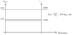
FIG. 4 is a schematic timing diagram illustrating exemplary output voltage and power characteristics at two discrete output voltage (and power) levels;
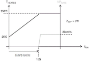
FIG. 5 is a schematic time diagram showing the rise in smoke source temperature (top graph), the rise in smoke smell mist rate (bottom graph) and their time or latency dependence at a first supply power level;
FIG. 6 is a schematic time diagram showing the rise in smoke source temperature (top graph), the rise in smoke smell mist rate (bottom graph) and their time or wait time dependence at a second supply power level;
7A, 7B, 7C are time charts illustrating exemplary changes in battery power output to a heater, smoke temperature versus time, and smoke generation rate (generation volume rate), respectively, during a smoke inhalation event according to the adaptive power control scheme of the present invention;
fig. 8 is an exemplary equivalent circuit model of a cartomizer for the electronic cigarette of fig. 1;
FIG. 9 is a schematic functional block diagram of an exemplary adaptive power supply control scheme in accordance with the present invention;
10A, 10B, 10C are time charts illustrating exemplary changes in detected inspiratory effort at the airflow sensor of FIG. 9, the associated adaptive power output to the heater, and the associated output waveform at the temperature estimator, respectively, during a smoke inhalation cycle.
Detailed Description
The present specification discloses an electronic vaping device comprising an inhalation sensor, a smoke source containing a vaporizable smoke substance, an electric heater for heating the smoke substance, and a power adjustment controller for controlling the supply of power to operate the heater; wherein the power conditioning controller is configured to adaptively supply operating power to the heater based on characteristics of a smoking inhalation event detected at the inhalation sensor.
The present specification also discloses a power regulating device for an electronic vaping apparatus, wherein the power regulating device includes a controller that adaptively supplies operating power to a heater to operate the electronic vaping apparatus in accordance with a received signal indicative of a characteristic of a puff inhalation event.
Exemplary embodiments of the present invention are described below.
The electronic cigarette 100 shown in fig. 1 includes: an elongate member similar in shape, size and appearance to a filter cigarette filled with tobacco and wrapped with paper. The elongate member is rigid, generally cylindrical, and includes a mouth piece 110 and a body 120 at opposite longitudinal ends. The mouthpiece in this example is a "cartomizer" shown in figure 1A, which is removable from the body 120 to facilitate replacement of the cartomizer when the flavourant contained in the cartomizer is exhausted or when a new taste is required. A cartomizer is a term in the field of electronic smoking devices that refers to a cartridge-type device that contains a flavoured liquid and an internal atomizer to produce a vapourised flavoured liquid.
The mouthpiece 110 in this example is adapted to correspond to the filter portion of a filter cigarette and comprises a tubular housing defining a suction end 112 and a connecting end 114. The inhalation end 112 is at the free longitudinal end of the electronic cigarette and is adapted to contact the mouth of a user during use to facilitate simulating a cigarette smoke. The connection end 114 is at a longitudinal end relative to the suction end 112 and includes a threaded connector portion 116 that releasably engages with a corresponding or complementary threaded connector portion 126 on the main body 120. The threaded connector portion 116 is an example of a releasable fastener that facilitates easy removal of the cartomizer from the body 120 when replacement is required.
The threaded connector portion 116 carries a pair of insulated electrical contacts thereon to provide electrical interconnection between the battery in the body and the heating element in the cartomizer. Electrical contacts for electrical interconnection with the battery are provided on a side surface of the threaded connector portion 116 opposite the main body 120 to facilitate electrical interconnection with the main body 120 by making electrical contact with corresponding contacts of the main body 120 when the mouthpiece 110 and the main body 120 are in secure mechanical engagement. The threaded connector portion 116 is metallic, while the electrical contact portions through the threaded connector are electrically insulated.
The portion of the tubular housing of the mouthpiece 110 extending between the suction end 112 and the threaded connector portion 116 comprises an outer peripheral wall and an inner peripheral wall. The outer peripheral wall, inner peripheral wall, suction end and connection end collectively define a reservoir 115 for filling the vaporizable smoke-flavoured liquid. The smoke flavored liquid is typically a solution made of Propylene Glycol (PG), Vegetable Glycerin (VG), and/or polyethylene glycol 400(PEG 400) mixed with a concentrated flavor. The flavored liquid optionally contains concentrated nicotine. An air passage 117 extending between the suction end and the connection end is defined by the inner circumferential wall. The air channel 117 also defines an air intake aperture of the mouthpiece 110. The assembly comprising the heating element 118 and wick 119 extends transversely through the air passage 117 at a location between the threaded connector portion 116 and the suction end 112. A wick 119 extends transversely between diametrically opposed sides of the inner peripheral wall and serves to wick the flavoured liquid from the reservoir 115 into the air passage 117. The heating element 118 is wound around the wick 119 and is adapted to vaporize the smoky liquid carried on the wick 119 upon heating operation of the heating element 118.
The body 120 includes an elongated and tubular member 122 having a first longitudinal end 124 and a second longitudinal end in contact with the mouthpiece 110. The tubular member 122 is generally cylindrical and has a transverse dimension substantially the same as that of the mouthpiece to provide geometric continuity between the body 120 and the mouthpiece 110. The first longitudinal end 124 of the tubular member 122 is distal from the mouth piece and forms a free end of the electronic cigarette 100. A threaded connector portion 126, complementary to the threaded connector portion 116 of the mouthpiece 110, is built on a second longitudinal end of the tubular member. An elongate and cylindrical battery 127 is inserted into the tubular member to provide power to operate the electronic cigarette 110 while leaving a longitudinally extending air channel through which air can pass from the first longitudinal end 124 to the second longitudinal end. The battery 127 is a pair of insulated electrical contacts wired (not shown) to the side surface of the threaded connector portion 126 oppositely facing the mouthpiece 120 to electrically interconnect corresponding contact terminals on the corresponding threaded connector portion 116 of the mouthpiece 120. The threaded connector portion 126 is metallic, while the portion of the electrical contact that passes through the threaded connector is insulated. To promote smooth movement of air across the cell, the cell has a cross-sectional dimension smaller than the interior void of the elongate member, and a longitudinally extending air guide is formed within the interior of the elongate body to support the cell and guide the air more smoothly through the space between the outside of the cell and the interior of the tubular member 122. A stop is mounted at the first longitudinal end to retain the battery 127 and other components within the tubular member 122. The stopper has holes to allow the air passage into and out of the tubular member and to allow the LED to be viewed from outside the electronic cigarette.
An electronics module 128, including LEDs (light emitting diodes), an inspiration sensor, a microprocessor (or microcontroller) and peripheral circuitry on a Printed Circuit Board (PCB), is mounted within the tubular member 122 at a location between the battery 122 and the first longitudinal end 124. The tubular member 122 may be made of metal or rigid plastic to provide sufficient strength to receive the battery and electronics module 128. The electronics module 128 is wired to the battery (wiring not shown). The LED faces the outside of the electronic cigarette and emits red light during operation in response to a user inhaling at the mouthpiece to simulate the color of an open flame produced during a conventional smoking procedure. The microprocessor is used to operate the heater by controlling the power to the heating element when an inhalation is detected by the inhalation sensor. The puff sensor and the microcontroller together define a power regulating device that controls the power to the heater to operate the electronic cigarette.
The inhalation sensor comprises an airflow sensor to detect a smoking inhalation event at the inhalation end. A smoking inhalation event in this context refers to the act of inhaling by a user (or smoker) by holding the mouth support of the electronic cigarette in the mouth and drawing air out of the electronic cigarette to simulate a draw. Although the puff sensor is disposed at the first longitudinal end 124 of the electronic cigarette and distal from the puff end 112, the mouthpiece 110 and the body 120 together define an airtight air passageway such that inhalation by a user at the puff end generates an incoming air flow that is detectable by the airflow sensor.
The inhalation sensor comprises an airflow sensor arranged to detect airflow at the first longitudinal end resulting from a smoking inhalation event occurring at the inhalation end. To facilitate detection of a smoking inhalation event, the airflow sensor has an associated electrical characteristic that can vary according to the characteristics of the smoking inhalation event. Examples of such event characteristics include, for example, the onset of a smoking event, the intensity of the inspiratory effort, and the variation in the intensity of the inspiratory effort. Capacitance and resistance values are typical relevant electrical characteristics that may be used. The microprocessor is coupled to the airflow sensor to measure the relevant electrical characteristics of the airflow sensor that may vary depending on the characteristics of the intake air flow. The measured electrical characteristic is then used to determine characteristics of the smoking inhalation event, such as onset or onset of a smoking inhalation event, inspiratory effort, and changes in inspiratory effort.
In the present example, the airflow sensor includes a plate-like detection member that can move, deflect, or deform when an intake airflow exceeding a predetermined threshold is encountered. Movement, deflection or deformation of the detection member of the airflow sensor will result in a change in the relevant electrical characteristic and the characteristic or changes thereof will be used by the microprocessor to determine the characteristics of a smoking inhalation event.
An exemplary airflow sensor and an example thereof for an electronic cigarette is described in WO 2011/033396a2 by the same inventor of the present application and that publication is incorporated herein by reference. Other airflow sensors and detectors suitable for use with electronic cigarettes may sometimes be used with electronic cigarettes where appropriate without loss of generality.
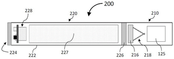
Figure 1B shows another example of an electronic cigarette 200 according to the present disclosure. The electronic cigarette 200 includes a body 220 and a mouth piece 210. The body 220 is identical to the body of the electronic cigarette 100, and all parts of the electronic cigarette 100 are incorporated herein by reference, with each corresponding number incremented by 100. The mouthpiece 210 is similar to that of the electronic cigarette 100 except that a heater/atomizer 218 and an ink cartridge 125 containing a flavoured liquid are provided within a rigid tubular housing to perform the function of atomizing a cartridge. The above description of the mouthpiece 110 is incorporated herein by reference, and each corresponding reference numeral is incremented by 100, as appropriate.
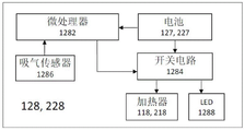
As shown in fig. 1C, the electronics module 128 includes a power conditioning device. The power conditioning device includes a microprocessor 1282, which is powered by the batteries 127, 227. The heaters 118, 218 are connected to the battery through a switching circuit 1284 that regulates the voltage and power supplied to the heaters 118, 218. The microprocessor 1282 is connected to an inhalation sensor 1286 to detect a characteristic of a puff inhalation, and the detected characteristic of the puff inhalation is used by the microprocessor 1282 to operate a switch circuit 1284 to regulate power to the heater and LED 1288. An exemplary operation of the microprocessor for regulating the operational power will be described below.
In use, a user inhales at the inhalation end 112, 212 of the electronic cigarette to smoke, which creates a low pressure region within the mouthpiece 110, 210. This low pressure area will cause outside air to enter the body 122, 222 through the first longitudinal end 124, 224, as the body and mouthpiece together form an airtight conduit. The outside air reaching the first longitudinal end will cause a momentary relative movement or deformation of the detection member of the airflow sensor. This instantaneous relative movement or deformation, or change in movement or deformation, of the plate-like member of the airflow sensor, when interpreted by the microprocessor, is converted into data indicative of the airflow direction and/or inspiratory effort. When the detected direction of airflow corresponds to a smoking inhalation and the detected inhalation force reaches a predetermined threshold, the microprocessor will activate the battery to operate the heater of the aerosol source to vaporize the smoke flavoured liquid within the aerosol source and cause the smoke flavoured vapour to pass through the mouthpiece and to the user. The aerosol source may be a cartomizer or a cartridge and atomizer type assembly without loss of generality. Smoking an inhalation in this context means that inhalation takes place in a manner similar to smoking at the inhalation end of the mouthpiece.
Since the smoke-flavoured liquid within the smoke source requires time to heat before vaporisation occurs, there is a perceptible time delay between the user's act of inhaling and the arrival of the smoke-flavoured vapour at the user. The delay time generally depends on the heat capacity of the smoke source and the instantaneous temperature. The heating delay time is referred to herein as the heating latency time. Sometimes this delay time can be as long as a few seconds, which is equivalent to the time of a typical smoking inhalation cycle. Such delays can make electronic smoking a strange and unrealistic experience. As noted, the output voltage of some batteries, particularly lithium ion batteries commonly used to power electronic cigarettes, will decrease with use, and thus the heating latency can be expected to deteriorate or increase with use or aging of the electronic cigarette. In this context, the time of a smoking inhalation cycle is the time between the start and end of an inhalation maneuver.
As shown in FIG. 2, the terminal voltage V of an exemplary lithium battery having a rated voltage of 4.2VOUTAnd gradually drops to about 3.2V after repeated use. In the example where the heater has an internal resistance of 3 Ω and direct resistance heating is used so that a terminal voltage is applied directly to and across the terminals of the resistive heater, the output power of the battery will drop rapidly as shown by the lower curve of fig. 3. The battery output power represented by the lower curve is according to the following formula POUT=VOUT 2/ROUTIn which R isOUT3 Ω. In addition to the increase of the heating waiting time, the battery terminal voltage VOUTThe loss of (b) also results in a reduction in power output, which in turn causes the rate of smoke generation during normal smoking operation to be significantly reduced.
The power management of the electronic cigarette of figures 1 and 1A is set to provide constant power to the electric heaterOr a substantially constant voltage to mitigate the deterioration of heating latency delay and performance degradation caused by long-term use. For example, a constant or substantially constant voltage as shown in FIG. 4 may be provided by the battery by using Pulse Width Modulation (PWM) techniques. PWM may be facilitated by a high frequency switching circuit driven by a microprocessor as a controller for the power regulating device of the electronic cigarette. By maintaining a constant or substantially constant voltage supply, heating latency can be kept short during the life of the battery. As shown in the lower curve of fig. 5, a short heating latency of about 0.3 seconds can be maintained. As shown in the upper curve of fig. 5, this heating wait time is the time for the smoke source to reach the boiling point of the smoke-flavoured liquid (about 250 ℃) from room temperature (about 25 ℃). After the smoke source's smoke liquid reaches its boiling point, smoke vapor is produced at a constant rate by this constant supply of electricity. In this example, the smoke vapour is at 50cm at a voltage supply of 4.2V to the heater 3The rate of/s.
While supplying a constant voltage to the resistive heater helps mitigate the degradation of heating latency delays and performance degradation caused by repeated use of the battery, it may not be entirely desirable to provide a constant dose rate of smoke vapor throughout the smoking inhalation process. For example, the continuous generation of the same amount of rate of smoke vapor after the user's peak suction has occurred may be excessive if not wasteful.
On the other hand, if a lower rate of smoke vapor is generated during steady state operation, the lower rate will mean that a lower operating level of operating power is supplied to the heater, which will result in longer heating latency. As shown in FIG. 6, lower production rates of smoke vapor under run state operation, e.g., at 20cm3At/s, it means a constant supply P of 3W to the heaterOUTThis translates into a longer latency of about 1.2s compared to a 0.3 second heating latency at 5W power.
To avoid the difficult side-to-side situation between selecting a longer heating wait time and an excess dose rate under steady state operation, the electronic cigarette of fig. 1 and 2 employs an adaptive power control scheme. Referring to fig. 7A, 7B and 7C, an exemplary implementation of the adaptive power supply control scheme is shown.
Referring to fig. 7A, push power is supplied to the heater when a smoking inhalation event is initiated. The push power is applied only for an initial time 10 during which the aerosol source heats up from room temperature to a vaporized state. A reduced power level is supplied to the heater after the aerosol source enters the boil-off state. The reduced power level is set to maintain the electronic cigarette in a running or operational state in which the smoke source will remain in a vaporized state. During the operating state time 20, a steady state quantity rate of smoke vapor is generated that is substantially lower than the quantity rate generated by the power supply at the boost power level when the smoke source is in a vaporized state. When a stronger inhalation is detected at the inhalation sensor, the power to the heater will increase during this more inhaled state 30 and the rate of production of smoke vapor will increase. A state of stronger inhalation herein refers to a state during which the strength of the inhalation force is higher than the inhalation strength required to maintain the electronic cigarette in a running or operating state. As the inhale intensity begins to decrease during the stronger inhale state 30, the power to the heater will follow and begin to decrease. As a result, the rate of production of the flavorful vapor will also decrease, and the decrease will stop when the steady state rate is reached. When the power supply to the heater is equal to the power for maintaining the operation or operating state, the power supply P to the heater OUTWill stop. In this example, P OUT5W in the push power supply and 3W in the run or operating state.
The adaptive powering scheme provides a more realistic smoking experience for the user, as the rate of production of smoke vapor substantially follows the variations in inspiratory strength.
Referring to fig. 7B, the smoke source heats up from room temperature (25 ℃) to its boiling or vaporization point (250 ℃) during an initial time 10 and will remain at the boiling or vaporization point during the time the electronic cigarette is in operation.
Referring to fig. 7C, after an initial time of 10 has elapsed, a significant amount of smoke vapor may begin to be produced. During time 20, the rate of production of the flavoured vapour is maintained at a steady state rate. The rate of production of the smoke vapor increases when a stronger inhalation is detected during the stronger inhalation state 30. In this example, the initial time 10 has a duration of 0.3 seconds, which is a short heating latency that is not noticeable by most users or smokers of the electronic smoking device.
In this example, battery power to the heater is regulated by a microprocessor of the power regulating device included in the electronics module 128. After the electronic cigarette is started, the running time 20 may be considered as a standby time during which no effective inhalation force is detected at the inhalation sensor.
The exemplary electronic cigarette of fig. 1 and 2 includes a capacitive airflow sensor, and an exemplary relationship between instantaneous air pressure and a related change in capacitance value detected by the airflow sensor resulting from an inhalation at the mouthpiece is shown in table 1 below:
| sensor pressure (Pa) | Change in capacitance (%) | C value |
| Atmospheric pressure (A) | 0.0% | C0 |
| A+100 | 0.8% | C1 |
| A+200 | 1.6% | C2 |
| A+400 | 3.2% | C3 |
| A+600 | 4.8% | C4 |
| A+800 | 6.4% | C5 |
TABLE 1
In this example, the above-described electrical characteristics of the capacitive airflow sensor are used by the microprocessor of the power modulating device of fig. 1C to determine the smoking inhalation characteristics as described below. In the present exemplary airflow sensor, the detected suction pressure of a +200Pa is set as the activation threshold pressure, which corresponds to the detected capacitance value C2. The maximum detectable inspiratory pressure at the inspiratory sensor is C5, i.e., a +800Pa, which represents a + 6.4% change in capacitance value compared to the capacitance value of the inspiratory sensor at atmospheric pressure. Supply of power P to the heaterOUTIs set such that on start-up, the heater will be supplied with a boost supply corresponding to the maximum available power output (5W). The instantaneous power to the heater will vary between a maximum power level (e.g. 5W) and a minimum power level (e.g. 3W). In this example, the power supply will gradually increase from a minimum power of 3W at C2 to a maximum power of 5W at C5, while the maximum power supply level is the same as the push power supply, which will be supplied when the maximum detectable suction pressure A +800Pa is detected. Conversely, the supply will gradually decrease from a maximum power of 5W at C5 to a minimum power of 3W at C2. An exemplary operation of an exemplary electronic cigarette will be described.
When there is no suction at the mouthpiece, the pressure at the airflow sensor will be atmospheric pressure a. Assuming that a +200Pa is set to the activation threshold pressure corresponding to detection of a smoking puff at the mouthpiece, the microprocessor will cause the electronic cigarette to begin operation by supplying a push power to the heater upon detection of a capacitance value corresponding to the activation threshold capacitance C2, as shown by operating region 10 in figure 7A. After the power-on application time has elapsed, the aerosol source will reach its vaporization or boiling temperature and the instantaneous heating power will depend on the instantaneous suction pressure. In this example, the instantaneous suction pressure is A +200Pa, and a running state of 3W will be supplied, as shown by the operating region 20 in FIG. 7A.
When the inspiratory effort, represented by the pressure at the inspiratory sensor, subsequently increases to a +400Pa, a +600Pa, and a +800Pa as shown by the operating region 30 in fig. 7A. The microprocessor will increase the power supply to the heater according to the measured capacitance values C3, C4 and C5, respectively. The increase is represented by the rising edge of the triangular portion of the region 30. When the inspiratory effort drops from the maximum detectable inspiratory pressure a +800Pa, the microprocessor will decrease the power supply based on the instantaneously detected capacitance value. The reduction is represented by the falling edge of the triangular portion of the region 30.
When the inspiratory effort drops to the activation threshold pressure, a +200Pa, the microprocessor reduces the power supply to a steady state level to maintain the electronic cigarette in a running or operational state in which the smoke source will remain in a vaporized state, as shown in operational area 40 of fig. 7A.
When the inspiratory effort further drops below the activation threshold pressure a +200Pa, for example, to a +100Pa, the microprocessor will cease power and turn off the heater to complete the puff inspiration cycle. In this example, pressures below a +200Pa would be considered non-smoking induced pressure events to avoid unintended activations.
In one example, the power to the heater may be maintained at a minimum power level or run state power level even when the inspiratory pressure drops below the activation pressure to maintain the aerosol source in a vaporized state. In the example, when the detected pressure is below the activation threshold pressure for a duration of time, say 1 second, the microprocessor will turn off the power supply and end the puff inhalation event until the next activation threshold pressure is detected at the inhalation sensor. When the microprocessor detects the next activation threshold pressure, it will restart the heater in the manner described above.
To facilitate determining or estimating the instantaneous temperature of the liquid in the cartomizer so that the microprocessor can adjust the power to the heater with reference to the instantaneous temperature of the liquid, an equivalent circuit model of the cartomizer as shown in figure 8 can be used as a suitable example. The equivalent circuit comprises a first resistor (R) connected in sequenceθx) And a second resistor (R)θy). The upstream end of the first resistor, which is not connected with the second resistor, is connected with the power supply end, and the downstream end of the second resistor, which is not connected with the first resistor, is connected with the shell of the atomized cartridge. The circuit further comprises a first capacitor (C)y) A housing connected to the cartomizer from a junction between the first resistance and the second resistance; and a second capacitance (C)x) Which is connected to the outer casing of the cartomizer from the upstream end of the first resistor.
As shown in fig. 8, the equivalent circuit has the following meanings.

As shown in fig. 9, the power to the cartomizer can be controlled based on the instantaneous temperature of the liquid in the cartomizer and the temperature change of the liquid, which can be estimated using the following equation:


wherein, PoFor instantaneous power output to the heater, VoIs the output voltage, RoIs the total resistance of the heater and Δ t is the heating time. T is ASet to 25 c as a suitable example.
As shown in fig. 10A, when the microprocessor detects a threshold inspiratory pressure at the airflow sensor, the microprocessor activates the heater by providing push power or ramp power from the battery to the heater. This initiation process, which includes a period of power supply or power ramp, will cause the smoke liquid to quickly reach its boiling point. When the boiling point is reached, the temperature of the smoke liquid will not continue to rise and the microprocessor will reduce the power supply to the operating power level so that the smoke volume generation rate is maintained at the operating level. When the user stops inhaling, the microprocessor will detect a change in air pressure at the airflow sensor and when the microprocessor detects a decrease in air pressure, which corresponds to a cessation of the smoking process, the power to the heater will be discontinued. When the above process occurs, the temperature of the smoke liquid decreases as shown in the third period of time of fig. 10A. When the user begins to inhale again, as shown in the fourth time period of figure 10A, the microprocessor begins to provide power to the heater again, which causes the liquid to boil with a short delay time, since the liquid is now at a temperature higher than ambient temperature.
Accordingly, the present invention discloses an adaptive power supply scheme in which the aerosol generation rate is set to be substantially determined by or dependent on the inspiratory effort at the inspiratory end of the device. In one example, the controller or microprocessor is configured to control the heater such that the power to the heater for heating the source of aerosol is dependent on the instantaneous inspiratory effort applied to the inspiratory end of the device.
In one example of the invention, the microprocessor is set to supply a plurality of discrete power levels to the heater in response to changes in inspiratory effort, as shown in fig. 10B. Where the same inspiratory capacitive sensor was used, but a plurality of inspiratory force levels as shown in table 2 were set.

TABLE 2
As shown in fig. 10C and table 2, four levels of inspiratory force (S1, S2, S3, S4) were set. As shown in table 2, the inspiratory effort level corresponds to the pressure level and the percentage change in capacitance value of the inspiratory sensor. As shown in fig. 10B, power is provided to the heater to push power when operation of the e-vapor device is initiated or initiated. When the smoke source begins to generate smoke and the amount of inspiratory effort is between the levels of S1 and S2, the power supply will drop from the push power supply level to the first operating power level of 1.5W. When the amount of inspiratory effort increases between the levels of S2 and S3, the power output is set to a second operating power level of 2.5W. When the amount of suction is further increased to a level between the levels of S3 and S4 (not shown), the power output is set to a third operating power level of 3.5W. When no inspiratory effort is detected, the power output to the heater will decrease to zero, as shown in the OFF segment of FIG. 10B. When the user inhales again, the push power will again be generated, as shown by the second power peak in fig. 10B. Because the temperature of the tobacco juice is higher than the ambient temperature T when the heater starts to heat again AThe duration (or width) of the powered peak is much shorter than the first power peak.
While the foregoing examples have been used to help illustrate the present invention, it should be understood that these examples are illustrative only and not limiting. For example, while an aerosol cartridge has been used as a suitable example, an atomizer or cartridge having a heating element and filled with liquid smoke may also be used without loss of generality. In addition, the above-described adaptive power supply examples may be used alone or in combination according to the preference of the user. Further, the exemplary scheme is illustrated using a plurality of 4 inhale power levels and 4 discrete power levels, but it should be understood that the levels used are for illustration only and are not limiting. Although the mouthpiece in the example is detachable from the body of the e-cigarette for ease of illustration, the mouthpiece may not be detachable from the body of the cigarette without loss of generality. While equivalent models are used for temperature estimation, the use of thermal sensors to detect the temperature of the smoke fluid may be a useful alternative.
Further, it should be readily understood by those skilled in the art that exemplary pressure values, capacitance values, changes in capacitance values, power supply values, timing values, and the like are provided to aid understanding.
Claims (18)
1. An electronic vaping device, comprising:
a reservoir configured to hold a liquid;
a heater configured to heat liquid drawn from the reservoir;
a switching circuit configured to control supply of operating power to the heater; and
a controller configured to control the switching circuit,
wherein, during a smoking event, the controller is configured to control the switching circuit to
Supplying the operating power at a boost supply level in response to detecting airflow through the electronic vaping device at or above a first threshold level,
upon detection of said airflow at or above a first threshold level, reducing said operating power from said boost supply level to an operational supply level after a boost heating time has elapsed, an
In response to detecting that airflow through the electronic vaping device is a stronger airflow above the first threshold level, increasing the operating power above the operational power level by an amount corresponding to an increase in airflow through the electronic vaping device from the first threshold level of airflow to the stronger airflow,
Wherein the first threshold level is an activation threshold pressure for activating an electronic vaping device;
the boost power level is a maximum operating power applied to the heater during a smoking event;
the operating power level is a minimum non-zero operating power to maintain vaporization of the heater liquid.
2. The electronic vaping device of claim 1, wherein the push heating time is less than 1 second.
3. The electronic vaping device of claim 1, further comprising:
a sensor configured to output a signal indicative of a level of airflow through the electronic vaping device; and wherein
The controller is further configured to detect a level of airflow through the electronic vaping device based on the signal output from the sensor.
4. The electronic vaping device of claim 3, wherein
The sensor comprises a capacitive airflow sensor having a capacitance value that varies in response to a level of airflow through the electronic vaping device.
5. The electronic vaping device of claim 1, wherein the controller is further configured to control the switching circuit to decrease the operating power from the push supply level to the run supply level and to increase the operating power above the run supply level without decreasing the operating power to 0.
6. The electronic vaping device of claim 1, wherein the electronic vaping device is in a state of being a passive vaping device
The controller is further configured to control the switching circuit to increase the operating power from the operational power supply level to a power level greater than the operational power supply level in response to detecting an airflow through the electronic vaping device being stronger than a first level of the airflow; and is
The power level greater than the operational power supply level is lower than the push power supply level.
7. The electronic vaping device of claim 1, wherein the controller is further configured to control the switching circuit to:
first, reducing the operating power to 0 in response to detecting a second level of airflow through the electronic vaping device, the second level of airflow being below the first threshold level;
secondly, increasing the operating power from 0 to the boost supply level in response to detecting a third level of airflow through the electronic vaping device, the third level of airflow being at or above the first threshold level; and
then, the operating power is reduced from the boost power level to the run power level after a boost heating time following detection of a third level of the airflow, the boost heating time following detection of the third level of the airflow being less than the boost heating time following the first level of the airflow.
8. An electronic vaping device, comprising:
a reservoir configured to hold a liquid;
a heater configured to heat liquid drawn from the reservoir;
a switching circuit configured to control supply of operating power to the heater; and
a controller configured to control the switching circuit to:
supplying the operating power at a boost power level in response to detecting that airflow through the electronic vaping device is at or above a first threshold level,
upon detecting the airflow at or above a first threshold level, reducing the operating power from the boost power level to an operating power level after a boost heating time, the operating power level being a non-zero power level, an
Increasing the operating power above the operational power supply level in response to detecting that airflow through the electronic vaping device is stronger airflow above the first threshold level,
wherein the first threshold level is an activation threshold pressure for activating an electronic vaping device;
the boost power level is a maximum operating power applied to the heater during a smoking event;
the operating power level is a minimum non-zero operating power to maintain vaporization of the heater liquid.
9. The electronic vaping device of claim 8, wherein the increase in operating power above the operational power supply level corresponds to an increase in airflow through the electronic vaping device above the first level of airflow.
10. The electronic vaping device of claim 8, wherein the controller is further configured to control the switching circuit to increase the operating power above the operational power level without decreasing the operating power to 0.
11. The electronic vaping device of claim 8,
the controller is further configured to control the switching circuit to increase the operating power from the operational power supply level to a power level greater than the operational power supply level in response to detecting that airflow through the electronic vaping device is stronger airflow above a first level of the airflow; and is provided with
The power level greater than the run power level is lower than the push power level.
12. The electronic vaping device of claim 8, further comprising:
a sensor configured to output a signal indicative of a level of airflow through the electronic vaping device; and wherein
The controller is further configured to detect a level of airflow through the electronic vaping device based on the signal output from the sensor.
13. The electronic vaping device of claim 12, wherein the set of buttons are configured to be activated by a user
The sensor comprises a capacitive airflow sensor having a capacitance value that varies in response to a level of airflow through the electronic vaping device.
14. An electronic vaping device, comprising:
a reservoir configured to hold a liquid;
a heater configured to heat liquid drawn from the reservoir;
a switching circuit configured to control supply of operating power to the heater; and
a controller configured to control the switching circuit to:
first supplying the operating power at a boost power level in response to detecting that airflow through the electronic vaping device is at or above a first threshold level,
secondly, after detecting said airflow at or above a first threshold level, after a first boost heating time has elapsed, reducing said operating power from said boost supply level to a run supply level,
again, reducing the operating power from the operational power supply level to 0 in response to detecting a second level of airflow through the electronic vaping device,
Then increasing the operating power from 0 to the boost supply level in response to detecting that airflow through the electronic vaping device is at or above the first threshold level, and
thereafter, upon detecting the airflow at or above the first threshold level, reducing the operating power from the boost power level to the run power level after a second boost heating time, the second boost heating time being less than the first boost heating time, has elapsed;
wherein the first threshold level is an activation threshold pressure for activating an electronic vaping device;
the boost power level is a maximum operating power applied to the heater during a smoking event;
the operating power level is a minimum non-zero operating power to maintain vaporization of the heater liquid.
15. The electronic vaping device of claim 14, wherein the second level of airflow is below the first threshold level.
16. The electronic vaping device of claim 14, wherein the first push heating time is less than 1 second.
17. The electronic vaping device of claim 14, further comprising:
a sensor configured to output a signal indicative of a level of airflow through the electronic vaping device; and wherein
The controller is further configured to detect a level of airflow through the electronic vaping device based on the signal output from the sensor.
18. The electronic vaping device of claim 17, wherein
The sensor comprises a capacitive airflow sensor having a capacitance value that varies in response to a level of airflow through the electronic vaping device.
Applications Claiming Priority (4)
| Application Number | Priority Date | Filing Date | Title |
|---|---|---|---|
| HK12109815.0 | 2012-10-05 | ||
| HK12109815 | 2012-10-05 | ||
| CN201380052134.1A CN104736005B (en) | 2012-10-05 | 2013-10-07 | Electronic cigarette device |
| PCT/IB2013/059166 WO2014054035A1 (en) | 2012-10-05 | 2013-10-07 | Electronic smoke apparatus |
Related Parent Applications (1)
| Application Number | Title | Priority Date | Filing Date |
|---|---|---|---|
| CN201380052134.1A Division CN104736005B (en) | 2012-10-05 | 2013-10-07 | Electronic cigarette device |
Publications (2)
| Publication Number | Publication Date |
|---|---|
| CN109123794A CN109123794A (en) | 2019-01-04 |
| CN109123794B true CN109123794B (en) | 2022-06-28 |
Family
ID=49598056
Family Applications (3)
| Application Number | Title | Priority Date | Filing Date |
|---|---|---|---|
| CN2013103015235A Pending CN103404969A (en) | 2012-10-05 | 2013-07-17 | Electronic cigarette device |
| CN201380052134.1A Active CN104736005B (en) | 2012-10-05 | 2013-10-07 | Electronic cigarette device |
| CN201810832874.1A Active CN109123794B (en) | 2012-10-05 | 2013-10-07 | Electronic cigarette device |
Family Applications Before (2)
| Application Number | Title | Priority Date | Filing Date |
|---|---|---|---|
| CN2013103015235A Pending CN103404969A (en) | 2012-10-05 | 2013-07-17 | Electronic cigarette device |
| CN201380052134.1A Active CN104736005B (en) | 2012-10-05 | 2013-10-07 | Electronic cigarette device |
Country Status (5)
| Country | Link |
|---|---|
| US (8) | US10111465B2 (en) |
| EP (3) | EP2903466B1 (en) |
| CN (3) | CN103404969A (en) |
| BR (1) | BR112015007500A2 (en) |
| WO (1) | WO2014054035A1 (en) |
Families Citing this family (190)
| Publication number | Priority date | Publication date | Assignee | Title |
|---|---|---|---|---|
| US10244793B2 (en) | 2005-07-19 | 2019-04-02 | Juul Labs, Inc. | Devices for vaporization of a substance |
| GB2502055A (en) | 2012-05-14 | 2013-11-20 | Nicoventures Holdings Ltd | Modular electronic smoking device |
| GB2502053B (en) | 2012-05-14 | 2014-09-24 | Nicoventures Holdings Ltd | Electronic smoking device |
| CN103404969A (en) | 2012-10-05 | 2013-11-27 | 佛山市新芯微电子有限公司 | Electronic cigarette device |
| GB2507103A (en) | 2012-10-19 | 2014-04-23 | Nicoventures Holdings Ltd | Electronic inhalation device |
| GB2507104A (en) | 2012-10-19 | 2014-04-23 | Nicoventures Holdings Ltd | Electronic inhalation device |
| US10034988B2 (en) | 2012-11-28 | 2018-07-31 | Fontem Holdings I B.V. | Methods and devices for compound delivery |
| TWI622969B (en) | 2012-12-17 | 2018-05-01 | 印奈克斯托股份有限公司 | Method and apparatus for marking manufactured items using physical characteristic |
| TWI608805B (en) | 2012-12-28 | 2017-12-21 | 菲利浦莫里斯製品股份有限公司 | Heated aerosol-generating device and method for generating aerosol with consistent properties |
| US10279934B2 (en) | 2013-03-15 | 2019-05-07 | Juul Labs, Inc. | Fillable vaporizer cartridge and method of filling |
| CN205385867U (en) * | 2013-06-17 | 2016-07-20 | 吉瑞高新科技股份有限公司 | Electronic cigarette |
| WO2014205694A1 (en) * | 2013-06-26 | 2014-12-31 | 吉瑞高新科技股份有限公司 | Electronic cigarette and method for outputting constant power of electronic cigarette |
| US10194693B2 (en) | 2013-09-20 | 2019-02-05 | Fontem Holdings 1 B.V. | Aerosol generating device |
| WO2015046420A1 (en) * | 2013-09-30 | 2015-04-02 | 日本たばこ産業株式会社 | Non-combusting flavor inhaler |
| GB2519101A (en) * | 2013-10-09 | 2015-04-15 | Nicoventures Holdings Ltd | Electronic vapour provision system |
| US10039321B2 (en) | 2013-11-12 | 2018-08-07 | Vmr Products Llc | Vaporizer |
| PL3082484T3 (en) | 2013-12-19 | 2020-05-18 | Philip Morris Products S.A. | Aerosol-generating system |
| US10076139B2 (en) | 2013-12-23 | 2018-09-18 | Juul Labs, Inc. | Vaporizer apparatus |
| USD842536S1 (en) | 2016-07-28 | 2019-03-05 | Juul Labs, Inc. | Vaporizer cartridge |
| US10058129B2 (en) | 2013-12-23 | 2018-08-28 | Juul Labs, Inc. | Vaporization device systems and methods |
| USD825102S1 (en) | 2016-07-28 | 2018-08-07 | Juul Labs, Inc. | Vaporizer device with cartridge |
| US10159282B2 (en) | 2013-12-23 | 2018-12-25 | Juul Labs, Inc. | Cartridge for use with a vaporizer device |
| KR102267997B1 (en) | 2013-12-23 | 2021-06-23 | 쥴 랩스, 인크. | Vaporization device systems and methods |
| US20160366947A1 (en) | 2013-12-23 | 2016-12-22 | James Monsees | Vaporizer apparatus |
| CN203723449U (en) * | 2014-02-12 | 2014-07-23 | 刘秋明 | Electronic cigarette |
| US10081531B2 (en) | 2014-02-28 | 2018-09-25 | Beyond Twenty Ltd. | Electronic vaporiser system |
| US10136674B2 (en) | 2014-02-28 | 2018-11-27 | Beyond Twenty Ltd. | Electronic vaporiser system |
| GB201413032D0 (en) | 2014-02-28 | 2014-09-03 | Beyond Twenty Ltd | Beyond 7 |
| US10285430B2 (en) | 2014-02-28 | 2019-05-14 | Ayr Ltd. | Electronic vaporiser system |
| US11085550B2 (en) | 2014-02-28 | 2021-08-10 | Ayr Ltd. | Electronic vaporiser system |
| US10588176B2 (en) | 2014-02-28 | 2020-03-10 | Ayr Ltd. | Electronic vaporiser system |
| US10091839B2 (en) | 2014-02-28 | 2018-10-02 | Beyond Twenty Ltd. | Electronic vaporiser system |
| US12295411B2 (en) | 2014-02-28 | 2025-05-13 | Ayr Ltd. | Electronic vaporizer system |
| PL2915443T3 (en) * | 2014-03-03 | 2020-01-31 | Fontem Holdings 1 B.V. | Electronic smoking device |
| CN104886773A (en) * | 2014-03-07 | 2015-09-09 | 惠州市吉瑞科技有限公司 | Electronic cigarette with accumulated tar removal function and method for removing accumulated tar of electronic cigarette |
| US10193364B2 (en) * | 2014-04-25 | 2019-01-29 | Shenzhen Kimsen Technology Co., Ltd | Electronic cigarette and method for reminding charging therein |
| MY189739A (en) * | 2014-05-02 | 2022-02-28 | Japan Tobacco Inc | Non-burning-type flavor inhaler |
| CN203873004U (en) * | 2014-05-07 | 2014-10-15 | 林光榕 | Double-voltage electronic cigarette control assembly |
| CN112772973B (en) * | 2014-05-12 | 2025-01-21 | 空气Ip控股有限公司 | A container of combustible material |
| US20150335070A1 (en) * | 2014-05-20 | 2015-11-26 | R.J. Reynolds Tobacco Company | Electrically-powered aerosol delivery system |
| GB201410171D0 (en) * | 2014-06-09 | 2014-07-23 | Nicoventures Holdings Ltd | Electronic vapour provision system |
| CN104049550B (en) * | 2014-06-19 | 2017-09-26 | 卓尔悦欧洲控股有限公司 | Control method and device of multi-output mode electronic cigarette |
| WO2015196354A1 (en) * | 2014-06-24 | 2015-12-30 | 深圳麦克韦尔股份有限公司 | Electronic cigarette and control method therefor |
| ES2991819T3 (en) * | 2014-06-27 | 2024-12-05 | Fontem Ventures Bv | Electronic smoking device and capsule system |
| WO2016000208A1 (en) * | 2014-07-01 | 2016-01-07 | 惠州市吉瑞科技有限公司 | Electronic cigarette and atomization method |
| WO2016029225A1 (en) | 2014-08-22 | 2016-02-25 | Fontem Holdings 2 B.V. | Method, system and device for controlling a heating element |
| TWI680726B (en) | 2014-10-13 | 2020-01-01 | 瑞士商菲利浦莫里斯製品股份有限公司 | Method of controlling an electric heater in an electrically heated smoking system and electrically heated smoking system |
| US11051554B2 (en) | 2014-11-12 | 2021-07-06 | Rai Strategic Holdings, Inc. | MEMS-based sensor for an aerosol delivery device |
| CN106102487B (en) * | 2014-11-27 | 2019-04-12 | 惠州市吉瑞科技有限公司 | A kind of electronic cigarette and its smog amount control method |
| KR102627987B1 (en) | 2014-12-05 | 2024-01-22 | 쥴 랩스, 인크. | Calibrated dose control |
| EP4183282B1 (en) | 2014-12-25 | 2025-12-17 | Fontem Ventures B.V. | Dynamic output power management for electronic smoking device |
| CN104571191B (en) * | 2015-01-22 | 2018-01-02 | 卓尔悦欧洲控股有限公司 | Temperature control system and its electronic cigarette |
| GB201501429D0 (en) * | 2015-01-28 | 2015-03-11 | British American Tobacco Co | Apparatus for heating aerosol generating material |
| PL229757B1 (en) | 2015-02-06 | 2018-08-31 | Esmoking Inst Spolka Z Ograniczona Odpowiedzialnoscia | Electronic device for producing aerosol and the method for producing aerosol |
| US10010111B2 (en) | 2015-03-04 | 2018-07-03 | Altria Client Services Llc | E-vaping device |
| CN104824848B (en) * | 2015-03-10 | 2018-04-03 | 深圳麦克韦尔股份有限公司 | Electronic cigarette |
| WO2016145634A1 (en) * | 2015-03-18 | 2016-09-22 | 惠州市吉瑞科技有限公司 | Heating method for heating wire of electronic cigarette atomizer, and electronic cigarette |
| CN104824851A (en) * | 2015-04-10 | 2015-08-12 | 矽翔微机电系统(上海)有限公司 | Electronic atomizer, atomization control method and physical sign data monitoring system |
| WO2016172821A1 (en) * | 2015-04-27 | 2016-11-03 | 惠州市吉瑞科技有限公司深圳分公司 | Electronic cigarette atomization control method and electronic cigarette control circuit |
| JP6395931B2 (en) * | 2015-05-29 | 2018-09-26 | 日本たばこ産業株式会社 | Non-burning flavor inhaler and aerosol delivery method |
| US10368399B2 (en) | 2015-06-10 | 2019-07-30 | Altria Client Services Llc | E-vaping device |
| WO2016210242A1 (en) | 2015-06-25 | 2016-12-29 | Altria Client Services Llc | Electronic vaping device having pressure sensor |
| GB2540135B (en) | 2015-07-01 | 2021-03-03 | Nicoventures Holdings Ltd | Electronic aerosol provision system |
| CN104983073A (en) * | 2015-07-07 | 2015-10-21 | 深圳市赛尔美电子科技有限公司 | Cigarette distillation device |
| US20170055574A1 (en) | 2015-08-31 | 2017-03-02 | British American Tobacco (Investments) Limited | Cartridge for use with apparatus for heating smokable material |
| CN108136141B (en) | 2015-09-01 | 2021-09-03 | 艾尔有限公司 | Electronic evaporator system |
| GB2542011A (en) * | 2015-09-01 | 2017-03-08 | Beyond Twenty Ltd | Electronic vaporiser system |
| US10939704B2 (en) | 2015-09-24 | 2021-03-09 | Philip Morris Products S.A. | Aerosol-generating article with capacitor |
| US10918134B2 (en) * | 2015-10-21 | 2021-02-16 | Rai Strategic Holdings, Inc. | Power supply for an aerosol delivery device |
| US20170119049A1 (en) | 2015-10-30 | 2017-05-04 | British American Tobacco (Investments) Limited | Article for Use with Apparatus for Heating Smokable Material |
| US20180317554A1 (en) | 2015-10-30 | 2018-11-08 | British American Tobacco (Investments) Limited | Article for use with apparatus for heating smokable material |
| US20170119051A1 (en) | 2015-10-30 | 2017-05-04 | British American Tobacco (Investments) Limited | Article for Use with Apparatus for Heating Smokable Material |
| US20170119050A1 (en) | 2015-10-30 | 2017-05-04 | British American Tobacco (Investments) Limited | Article for Use with Apparatus for Heating Smokable Material |
| WO2017118553A1 (en) | 2016-01-07 | 2017-07-13 | Philip Morris Products S.A. | Aerosol-generating device with sealed compartment |
| US10258086B2 (en) * | 2016-01-12 | 2019-04-16 | Rai Strategic Holdings, Inc. | Hall effect current sensor for an aerosol delivery device |
| US20170215478A1 (en) | 2016-01-28 | 2017-08-03 | Stratos Product Development Llc | Vapor delivery systems and methods |
| WO2017139675A1 (en) | 2016-02-11 | 2017-08-17 | Pax Labs, Inc. | Securely attaching cartridges for vaporizer devices |
| MX377347B (en) | 2016-02-11 | 2025-03-07 | Juul Labs Inc | Fillable vaporizer cartridge and method of filling |
| CN209002919U (en) * | 2016-02-22 | 2019-06-21 | 惠州市吉瑞科技有限公司深圳分公司 | Electronic cigarette |
| US10405582B2 (en) * | 2016-03-10 | 2019-09-10 | Pax Labs, Inc. | Vaporization device with lip sensing |
| CN118319066A (en) | 2016-04-22 | 2024-07-12 | 尤尔实验室有限公司 | Aerosol device with spacer material |
| FR3050618B1 (en) * | 2016-05-02 | 2023-12-15 | Sarl Gaiatrend | METHOD FOR CONTROLLING A VAPING DEVICE AND VAPING DEVICE FOR IMPLEMENTING THE METHOD |
| US10111468B2 (en) | 2016-06-13 | 2018-10-30 | Db Innovation Inc. | Vaporization device |
| USD849996S1 (en) | 2016-06-16 | 2019-05-28 | Pax Labs, Inc. | Vaporizer cartridge |
| USD848057S1 (en) | 2016-06-23 | 2019-05-07 | Pax Labs, Inc. | Lid for a vaporizer |
| USD836541S1 (en) | 2016-06-23 | 2018-12-25 | Pax Labs, Inc. | Charging device |
| USD851830S1 (en) | 2016-06-23 | 2019-06-18 | Pax Labs, Inc. | Combined vaporizer tamp and pick tool |
| PL3478104T3 (en) * | 2016-06-29 | 2023-05-08 | Nicoventures Trading Limited | Apparatus for heating smokable material |
| KR102468749B1 (en) | 2016-06-29 | 2022-11-17 | 니코벤처스 트레이딩 리미티드 | Apparatus for heating smokable material |
| US12478096B2 (en) | 2016-06-29 | 2025-11-25 | Nicoventures Trading Limited | Apparatus for heating smokable material |
| US10757973B2 (en) | 2016-07-25 | 2020-09-01 | Fontem Holdings 1 B.V. | Electronic cigarette with mass air flow sensor |
| US10051893B2 (en) * | 2016-07-25 | 2018-08-21 | Fontem Holdings 1 B.V. | Apparatus and method for communication and negotiation of charge rate between electronic smoking device and charger |
| CN106292772A (en) * | 2016-08-18 | 2017-01-04 | 陈镇江 | A electronic cigarette temperature control system based on joule mode |
| CN106388002B (en) * | 2016-09-13 | 2019-12-27 | 卓尔悦欧洲控股有限公司 | Electronic cigarette and cigarette liquid control method |
| CN106820266A (en) * | 2016-09-19 | 2017-06-13 | 卓尔悦欧洲控股有限公司 | A kind of electronic cigarette and its control method |
| EP3562537B1 (en) * | 2016-12-30 | 2024-03-06 | JT International S.A. | Electrically operated aerosol generation system |
| EP3562342B1 (en) * | 2016-12-30 | 2025-07-30 | JT International S.A. | Electrically operated aerosol generation system |
| GB201700812D0 (en) | 2017-01-17 | 2017-03-01 | British American Tobacco Investments Ltd | Apparatus for heating smokable material |
| EP4118989A1 (en) * | 2017-01-18 | 2023-01-18 | KT&G Corporation | Fine particle generating device |
| CN108338414B (en) * | 2017-01-25 | 2022-05-27 | 贵州中烟工业有限责任公司 | Control method and control system for electric heating smoking system |
| US20180220697A1 (en) * | 2017-02-03 | 2018-08-09 | Altria Client Services Llc | Methods and systems for improving stability of pre-vapor formulations of e-vaping devices |
| GB201705550D0 (en) * | 2017-04-06 | 2017-05-24 | British American Tobacco Investments Ltd | Electronic vapour provision device with variable power supply |
| CN108685182B (en) * | 2017-04-11 | 2020-06-16 | 研能科技股份有限公司 | Electronic cigarette |
| CN108685183B (en) * | 2017-04-11 | 2020-09-01 | 研能科技股份有限公司 | electronic cigarette |
| CN108685185B (en) * | 2017-04-11 | 2020-06-16 | 研能科技股份有限公司 | Electronic cigarette |
| CN108685179A (en) * | 2017-04-11 | 2018-10-23 | 研能科技股份有限公司 | Electronic cigarette |
| CN108685177B (en) * | 2017-04-11 | 2020-06-16 | 研能科技股份有限公司 | electronic cigarette |
| TWI642368B (en) | 2017-04-11 | 2018-12-01 | 研能科技股份有限公司 | Electronic cigarette |
| CN108685178B (en) * | 2017-04-11 | 2020-06-16 | 研能科技股份有限公司 | Electronic cigarette |
| CN108685180B (en) * | 2017-04-11 | 2020-06-16 | 研能科技股份有限公司 | electronic cigarette |
| CN108685181B (en) * | 2017-04-11 | 2020-06-16 | 研能科技股份有限公司 | Electronic cigarette |
| CN110430768A (en) * | 2017-04-24 | 2019-11-08 | 日本烟草产业株式会社 | Aerosol generating device and control method and program for aerosol generating device |
| TWI730082B (en) * | 2017-04-24 | 2021-06-11 | 日商日本煙草產業股份有限公司 | Aerosol generating apparatus and control method and program product for the same |
| TWI691281B (en) * | 2017-04-24 | 2020-04-21 | 日商日本煙草產業股份有限公司 | Aerosol generating apparatus and control method and program product for the same |
| EA201991564A1 (en) * | 2017-04-24 | 2019-09-30 | Джапан Тобакко Инк. | AEROSOL-GENERATING DEVICE, METHOD FOR MANAGING AEROSOL-GENERATING DEVICE AND PROGRAM |
| WO2018198154A1 (en) | 2017-04-24 | 2018-11-01 | 日本たばこ産業株式会社 | Aerosol generation apparatus, method for controlling aerosol generation apparatus, and program |
| CN108968151B (en) * | 2017-05-31 | 2020-06-16 | 研能科技股份有限公司 | electronic cigarette |
| CN107280072A (en) | 2017-06-19 | 2017-10-24 | 深圳市合元科技有限公司 | Electronic cigarette and its control method |
| US10603459B2 (en) | 2017-07-20 | 2020-03-31 | Eric Kotch | Variable viscosity vaporizer cartridge |
| CN107373759A (en) * | 2017-07-21 | 2017-11-24 | 深圳市新宜康电子技术有限公司 | The startup method that electronic smoke atomizer quickly heats |
| CN107455799B (en) * | 2017-09-05 | 2024-02-27 | 惠州市新泓威科技有限公司 | Electronic cigarette that can control the amount of smoke and its control method |
| USD887632S1 (en) | 2017-09-14 | 2020-06-16 | Pax Labs, Inc. | Vaporizer cartridge |
| EP4201239A1 (en) | 2017-09-15 | 2023-06-28 | Nicoventures Trading Limited | Apparatus for heating smokable material |
| CN107692319B (en) * | 2017-10-18 | 2024-01-12 | 深圳市新宜康科技股份有限公司 | Immersive fuel supply electronic cigarette and its working method |
| IL263217B (en) | 2017-11-24 | 2022-06-01 | Juul Labs Inc | Emission sensing and power circuit for vaporizers |
| GB201721821D0 (en) | 2017-12-22 | 2018-02-07 | Nicoventures Holdings Ltd | Electronic aerosol provision system |
| US11020544B2 (en) * | 2017-12-29 | 2021-06-01 | Shenzhen Jianan Technology Co., Limited | Composite heating type flue-curing device and composite heating method for cigarettes |
| CA3128462A1 (en) | 2018-02-14 | 2019-08-22 | Zenigata Llc | Vaporization system with integrated heaters |
| GB201803648D0 (en) | 2018-03-07 | 2018-04-25 | Nicoventures Trading Ltd | Electronic aerosol provision system |
| CN110299906B (en) * | 2018-03-21 | 2023-03-10 | 湖南中烟工业有限责任公司 | A working control circuit and control method of an ultrasonic atomizing sheet |
| US11202872B2 (en) * | 2018-04-06 | 2021-12-21 | Mark James Grote | Selectively activate-able heating-element system with two-or-more heating-elements |
| CN108449811B (en) * | 2018-04-13 | 2024-02-13 | 深圳瀚星翔科技有限公司 | Temperature intelligent control system for electronic heating device and control method thereof |
| CN108991602B (en) * | 2018-04-13 | 2020-05-05 | 赫斯提亚深圳生物科技有限公司 | A kind of aerosol generating device and heating control method thereof |
| CA3100749A1 (en) | 2018-05-29 | 2019-12-05 | Juul Labs, Inc. | Vaporizer device with cartridge |
| JP6968848B2 (en) * | 2018-06-20 | 2021-11-17 | 深▲せん▼市合元科技有限公司Shenzhen First Union Technology Co., Ltd | How to control e-cigarettes and e-cigarettes |
| MY206004A (en) | 2018-06-21 | 2024-11-23 | Philip Morris Products Sa | Improved control of aerosol production in an aerosol-generating system |
| KR102116118B1 (en) * | 2018-07-18 | 2020-05-27 | 주식회사 케이티앤지 | Method for controlling temperature of heater of aerosol generator and apparatus thereof |
| CN110326817B (en) * | 2019-01-11 | 2020-11-24 | 深圳雾芯科技有限公司 | A kind of electronic cigarette power output power control method and electronic cigarette |
| WO2020034772A1 (en) * | 2018-08-17 | 2020-02-20 | 深圳雾芯科技有限公司 | Atomization device and method therefor |
| CN108835718B (en) * | 2018-08-18 | 2020-11-03 | 深圳市合元科技有限公司 | Electronic cigarette power control method and electronic cigarette |
| CN208909131U (en) * | 2018-08-20 | 2019-05-31 | 常州市派腾电子技术服务有限公司 | Control circuit and electronic cigarette |
| CN119279271A (en) | 2018-09-28 | 2025-01-10 | 菲利普莫里斯生产公司 | Aerosol generating device |
| WO2020082040A1 (en) | 2018-10-19 | 2020-04-23 | Juul Labs, Inc. | Charging adapter for vaporizer device |
| CA3118504A1 (en) | 2018-11-08 | 2020-05-14 | Juul Labs, Inc. | Vaporizer device with more than one heating element |
| CN109452690A (en) * | 2018-11-09 | 2019-03-12 | 深圳市麦格米特控制技术有限公司 | Low-power consumption temprature control method, device and electronic cigarette |
| KR102199794B1 (en) * | 2018-11-16 | 2021-01-07 | 주식회사 케이티앤지 | Method for controlling power of heater of aerosol generating apparatus including continuous use function and apparatus thereof |
| US11592793B2 (en) | 2018-11-19 | 2023-02-28 | Rai Strategic Holdings, Inc. | Power control for an aerosol delivery device |
| JP6609687B1 (en) * | 2018-12-27 | 2019-11-20 | 日本たばこ産業株式会社 | Power supply unit for aerosol inhaler, its control method and control program |
| CN113939203A (en) | 2019-01-15 | 2022-01-14 | 尤尔实验室有限公司 | Evaporator device |
| US11523470B2 (en) * | 2019-01-18 | 2022-12-06 | Altria Client Services Llc | Non-combustible aerosol system and pre-aerosol formulation housing |
| CN109730360A (en) * | 2019-01-21 | 2019-05-10 | 深圳麦克韦尔股份有限公司 | The control method of electronic atomization device and its heating element |
| EP3711550A1 (en) * | 2019-03-22 | 2020-09-23 | Nerudia Limited | Smoking substitute system |
| CN109907379B (en) * | 2019-04-10 | 2021-10-26 | 深圳市卓力能技术有限公司 | Atomization device and output control method thereof |
| CN111838755B (en) * | 2019-04-25 | 2025-07-11 | 常州市派腾电子技术服务有限公司 | Electronic cigarette and control method thereof |
| KR102252458B1 (en) * | 2019-04-30 | 2021-05-14 | 주식회사 케이티앤지 | Aerosol generating device and operation method thereof |
| CN110236226A (en) * | 2019-04-30 | 2019-09-17 | 深圳市基克纳科技有限公司 | Atomizer with trigger protection |
| CN110432549B (en) * | 2019-06-12 | 2024-06-18 | 深圳市合元科技有限公司 | Aerosol Generating System |
| CN110432547A (en) * | 2019-06-12 | 2019-11-12 | 深圳市合元科技有限公司 | Aerosol Generating System |
| CN110200326B (en) * | 2019-06-26 | 2020-07-17 | 深圳市吉迩科技有限公司 | A kind of electronic cigarette power incremental control method and system |
| CN110279156A (en) | 2019-06-27 | 2019-09-27 | 深圳雾芯科技有限公司 | Electronic atomizer device, electronic atomizer device main body, and operation method |
| KR102400048B1 (en) | 2019-09-25 | 2022-05-19 | 주식회사 케이티앤지 | Aerosol generating device and control method thereof |
| GB201914979D0 (en) * | 2019-10-16 | 2019-11-27 | Nicoventures Trading Ltd | Aerosol delivery device |
| CN111011928A (en) * | 2019-11-21 | 2020-04-17 | 南京智晟达自动化科技有限公司 | An electronic smoke device that can reduce harm |
| CN112512139B (en) * | 2020-12-11 | 2023-06-23 | 深圳市新宜康科技股份有限公司 | Heating control method of heating component and electronic heating device |
| CN111528531B (en) * | 2020-04-30 | 2023-06-23 | 歌尔微电子股份有限公司 | Electronic cigarette detection device, detection method and electronic cigarette |
| CN111887507A (en) * | 2020-07-31 | 2020-11-06 | 深圳市吉迩科技有限公司 | Method for adaptively adjusting power, storage medium and aerosol generating device |
| CN112043010B (en) * | 2020-09-02 | 2024-05-28 | 深圳市云熙智能有限公司 | Low-temperature smoking set and method and device for collecting user data based on low-temperature smoking set |
| CN112006338B (en) * | 2020-09-14 | 2023-11-14 | 深圳雷炎科技有限公司 | Electronic cigarette power adjustment method, device, storage medium and electronic cigarette |
| CN112289602A (en) * | 2020-09-30 | 2021-01-29 | 深圳市吉迩科技有限公司 | Temperature-adjustable key assembly, temperature-adjustable method and aerosol generating device |
| CN112056634B (en) * | 2020-10-10 | 2023-03-14 | 云南中烟工业有限责任公司 | Method for controlling electric heating smoking set to heat cigarettes |
| WO2022079679A1 (en) * | 2020-10-15 | 2022-04-21 | Smart Chip Microelectronic Co. Limited | Electronic cigarettes and control devices thereof |
| CN112273731B (en) * | 2020-11-19 | 2022-08-02 | 钰泰半导体股份有限公司 | Control chip of electronic cigarette silicon microphone with double heating wires and control method thereof |
| CN112841753B (en) * | 2020-12-31 | 2022-06-07 | 四川三联新材料有限公司 | Heat-generating body temperature control method, temperature control device and aerosol generating device |
| KR102522678B1 (en) * | 2020-12-31 | 2023-04-17 | 주식회사 케이티앤지 | Aerosol generating device |
| US12520880B2 (en) | 2021-01-18 | 2026-01-13 | Altria Client Services Llc | Heat-not-burn (HNB) aerosol-generating devices including energy based heater control, and methods of controlling a heater |
| US11789476B2 (en) * | 2021-01-18 | 2023-10-17 | Altria Client Services Llc | Heat-not-burn (HNB) aerosol-generating devices including intra-draw heater control, and methods of controlling a heater |
| JP2021065238A (en) * | 2021-01-27 | 2021-04-30 | 日本たばこ産業株式会社 | Aerosol generating device, method of controlling aerosol generating device, and program |
| EP4059552A1 (en) * | 2021-03-18 | 2022-09-21 | JT International SA | Control device for controlling electrical power supply in an aerosol generation device |
| EP4147594B1 (en) * | 2021-04-13 | 2025-02-26 | Shenzhen Smoore Technology Limited | Heating control method and electronic atomization device |
| CN113180312A (en) * | 2021-04-27 | 2021-07-30 | 深圳市讴可电子科技有限公司 | Atomized electronic cigarette control method and device, atomized electronic cigarette and storage medium |
| JP7756246B2 (en) * | 2021-10-19 | 2025-10-17 | ケーティー アンド ジー コーポレイション | Aerosol Generator |
| JP7736800B2 (en) * | 2021-10-29 | 2025-09-09 | 日本たばこ産業株式会社 | Suction device, substrate, and control method |
| GB202200777D0 (en) * | 2022-01-21 | 2022-03-09 | Nicoventures Trading Ltd | Aerosol provision systems |
| CN116818383A (en) * | 2022-06-24 | 2023-09-29 | 陈瑶 | Detection device of range hood and detection method adopting same |
| CN115067577B (en) * | 2022-07-12 | 2023-10-31 | 无锡市晶源微电子股份有限公司 | Airflow sensing device and electronic cigarette device |
| US12550942B2 (en) | 2022-09-19 | 2026-02-17 | Altria Client Services Llc | Session control system |
| CN121941429A (en) * | 2023-10-03 | 2026-04-28 | 菲利普莫里斯生产公司 | Aerosol generating device operable in an aerosol release mode and in a pause mode |
| WO2025073626A1 (en) * | 2023-10-03 | 2025-04-10 | Philip Morris Products S.A. | Aerosol-generating device operable in an aerosol-releasing mode and in a pause mode |
| WO2026027530A1 (en) * | 2024-07-31 | 2026-02-05 | Jt International Sa | An aerosol generating device |
| CN119385355B (en) * | 2024-12-30 | 2025-09-19 | 湖北中烟工业有限责任公司 | Self-regulating heating temperature control method and system for heating smoking set |
Family Cites Families (25)
| Publication number | Priority date | Publication date | Assignee | Title |
|---|---|---|---|---|
| US4947874A (en) * | 1988-09-08 | 1990-08-14 | R. J. Reynolds Tobacco Company | Smoking articles utilizing electrical energy |
| EP0358114A3 (en) * | 1988-09-08 | 1990-11-14 | R.J. Reynolds Tobacco Company | Aerosol delivery articles utilizing electrical energy |
| US4951174A (en) | 1988-12-30 | 1990-08-21 | United Technologies Corporation | Capacitive pressure sensor with third encircling plate |
| US6040560A (en) * | 1996-10-22 | 2000-03-21 | Philip Morris Incorporated | Power controller and method of operating an electrical smoking system |
| ES2473591T3 (en) * | 2001-07-31 | 2014-07-07 | Philip Morris Products S.A. | Method and apparatus for generating volatilized liquids |
| CN201067079Y (en) * | 2006-05-16 | 2008-06-04 | 韩力 | Simulated aerosol inhaler |
| WO2008015918A1 (en) * | 2006-08-01 | 2008-02-07 | Japan Tobacco Inc. | Aerosol suction device, and its sucking method |
| US7726320B2 (en) | 2006-10-18 | 2010-06-01 | R. J. Reynolds Tobacco Company | Tobacco-containing smoking article |
| DE102007011120A1 (en) | 2007-03-07 | 2008-09-11 | Bel Air International Corp., Nashville | Electrically-rechargeable, smoke-free cigarette, includes sensor measuring airflow, with controller to time and modulate electrical heating which vaporizes nicotine |
| EP2113178A1 (en) * | 2008-04-30 | 2009-11-04 | Philip Morris Products S.A. | An electrically heated smoking system having a liquid storage portion |
| EP2143346A1 (en) * | 2008-07-08 | 2010-01-13 | Philip Morris Products S.A. | A flow sensor system |
| EP2201850A1 (en) | 2008-12-24 | 2010-06-30 | Philip Morris Products S.A. | An article including identification information for use in an electrically heated smoking system |
| CN101518361B (en) * | 2009-03-24 | 2010-10-06 | 北京格林世界科技发展有限公司 | High-simulation electronic cigarette |
| CN201482667U (en) * | 2009-04-28 | 2010-05-26 | 微创高科有限公司 | Electronic atomizer |
| DE102009029768B4 (en) | 2009-06-18 | 2013-02-21 | Zetzig Ab | Device for delivering nicotine |
| EP2477514B2 (en) * | 2009-09-18 | 2021-12-29 | Altria Client Services LLC | Electronic cigarette |
| EP2327318A1 (en) * | 2009-11-27 | 2011-06-01 | Philip Morris Products S.A. | An electrically heated smoking system with internal or external heater |
| CN201830900U (en) | 2010-06-09 | 2011-05-18 | 李永海 | Tobacco juice atomization device for electronic cigarette |
| LT2982255T (en) * | 2010-08-24 | 2019-08-12 | Jt International Sa | INHALATION DEVICE WITH MATERIALS ADJUSTMENT |
| EP2454956A1 (en) * | 2010-11-19 | 2012-05-23 | Philip Morris Products S.A. | An electrically heated smoking system comprising at least two units |
| EP2460423A1 (en) * | 2010-12-03 | 2012-06-06 | Philip Morris Products S.A. | An electrically heated aerosol generating system having improved heater control |
| EP2672848A4 (en) * | 2011-02-09 | 2017-12-06 | SIS Resources, Ltd. | Variable power control electronic cigarette |
| CN102106611B (en) | 2011-03-28 | 2013-01-16 | 深圳市康泰尔电子有限公司 | Electronic cigarette |
| KR101184758B1 (en) | 2012-01-13 | 2012-09-19 | 이영인 | Cartridge of electric cigarette for preventing leakage |
| CN103404969A (en) * | 2012-10-05 | 2013-11-27 | 佛山市新芯微电子有限公司 | Electronic cigarette device |
-
2013
- 2013-07-17 CN CN2013103015235A patent/CN103404969A/en active Pending
- 2013-10-07 EP EP13844300.7A patent/EP2903466B1/en active Active
- 2013-10-07 US US14/433,556 patent/US10111465B2/en active Active
- 2013-10-07 WO PCT/IB2013/059166 patent/WO2014054035A1/en not_active Ceased
- 2013-10-07 BR BR112015007500A patent/BR112015007500A2/en not_active IP Right Cessation
- 2013-10-07 EP EP21151712.3A patent/EP3831231B1/en active Active
- 2013-10-07 CN CN201380052134.1A patent/CN104736005B/en active Active
- 2013-10-07 EP EP24223682.6A patent/EP4508994A3/en active Pending
- 2013-10-07 CN CN201810832874.1A patent/CN109123794B/en active Active
-
2018
- 2018-07-25 US US16/044,870 patent/US10123570B1/en active Active
- 2018-10-01 US US16/148,276 patent/US10244796B2/en active Active
-
2019
- 2019-03-26 US US16/364,656 patent/US10568363B2/en active Active
-
2020
- 2020-01-13 US US16/740,952 patent/US11103011B2/en active Active
-
2021
- 2021-07-26 US US17/385,173 patent/US11684088B2/en active Active
-
2023
- 2023-05-12 US US18/316,388 patent/US12082619B2/en active Active
-
2024
- 2024-08-02 US US18/793,182 patent/US20240389667A1/en active Pending
Also Published As
| Publication number | Publication date |
|---|---|
| EP2903466A1 (en) | 2015-08-12 |
| US20150313284A1 (en) | 2015-11-05 |
| BR112015007500A2 (en) | 2017-07-04 |
| US12082619B2 (en) | 2024-09-10 |
| US20190029325A1 (en) | 2019-01-31 |
| CN103404969A (en) | 2013-11-27 |
| EP2903466A4 (en) | 2015-12-09 |
| WO2014054035A1 (en) | 2014-04-10 |
| US20230329349A1 (en) | 2023-10-19 |
| US20210345680A1 (en) | 2021-11-11 |
| CN104736005B (en) | 2018-08-21 |
| EP4508994A2 (en) | 2025-02-19 |
| US20180325181A1 (en) | 2018-11-15 |
| EP3831231A1 (en) | 2021-06-09 |
| US10123570B1 (en) | 2018-11-13 |
| US20240389667A1 (en) | 2024-11-28 |
| US20190216137A1 (en) | 2019-07-18 |
| US11103011B2 (en) | 2021-08-31 |
| US10244796B2 (en) | 2019-04-02 |
| CN104736005A (en) | 2015-06-24 |
| EP3831231B1 (en) | 2025-01-08 |
| EP4508994A3 (en) | 2025-04-30 |
| CN109123794A (en) | 2019-01-04 |
| US10111465B2 (en) | 2018-10-30 |
| EP2903466B1 (en) | 2021-02-17 |
| US11684088B2 (en) | 2023-06-27 |
| US20200187557A1 (en) | 2020-06-18 |
| US10568363B2 (en) | 2020-02-25 |
Similar Documents
| Publication | Publication Date | Title |
|---|---|---|
| CN109123794B (en) | Electronic cigarette device | |
| US10568359B2 (en) | Sensor for an aerosol delivery device | |
| JP6723471B2 (en) | Aerosol generation system with adjustable pump flow rate | |
| KR102707899B1 (en) | Differential pressure sensor for aerosol delivery device | |
| JP2023103468A (en) | Control unit, aerosol generator, method and program for controlling heater, and smoking article | |
| KR102554827B1 (en) | Electronic vapour provision system | |
| JP7117390B2 (en) | Control unit, aerosol generator, method and program for controlling heater, and smoking article | |
| JP6410193B2 (en) | Heating control arrangement for electronic smoking articles and related systems and methods | |
| JP2021533758A (en) | Aerosol delivery device with charging circuit | |
| WO2020039589A1 (en) | Suction component generator, method for controlling suction component generator, and program therefor | |
| CN112752521A (en) | Double-battery electronic cigarette | |
| JP7190554B2 (en) | Control unit, aerosol generator, method and program for controlling heater, and smoking article | |
| CN121586525A (en) | Power controller for aerosol delivery systems |
Legal Events
| Date | Code | Title | Description |
|---|---|---|---|
| PB01 | Publication | ||
| PB01 | Publication | ||
| SE01 | Entry into force of request for substantive examination | ||
| SE01 | Entry into force of request for substantive examination | ||
| GR01 | Patent grant | ||
| GR01 | Patent grant |