CN1092811C - Paper feeder - Google Patents
Paper feeder Download PDFInfo
- Publication number
- CN1092811C CN1092811C CN96104038A CN96104038A CN1092811C CN 1092811 C CN1092811 C CN 1092811C CN 96104038 A CN96104038 A CN 96104038A CN 96104038 A CN96104038 A CN 96104038A CN 1092811 C CN1092811 C CN 1092811C
- Authority
- CN
- China
- Prior art keywords
- paper
- detection block
- size
- detection
- signal generating
- Prior art date
- Legal status (The legal status is an assumption and is not a legal conclusion. Google has not performed a legal analysis and makes no representation as to the accuracy of the status listed.)
- Expired - Fee Related
Links
- 238000001514 detection method Methods 0.000 claims abstract description 180
- 230000007246 mechanism Effects 0.000 claims description 9
- 238000000034 method Methods 0.000 description 12
- 230000008569 process Effects 0.000 description 7
- 230000009471 action Effects 0.000 description 6
- 238000006073 displacement reaction Methods 0.000 description 3
- 238000005192 partition Methods 0.000 description 3
- 238000012360 testing method Methods 0.000 description 3
- 230000008859 change Effects 0.000 description 2
- 238000010586 diagram Methods 0.000 description 2
- 238000012546 transfer Methods 0.000 description 2
- 238000004140 cleaning Methods 0.000 description 1
- 230000007547 defect Effects 0.000 description 1
- 238000013461 design Methods 0.000 description 1
- 230000005611 electricity Effects 0.000 description 1
- 230000007274 generation of a signal involved in cell-cell signaling Effects 0.000 description 1
- 238000003780 insertion Methods 0.000 description 1
- 230000037431 insertion Effects 0.000 description 1
- 238000009434 installation Methods 0.000 description 1
- 230000004044 response Effects 0.000 description 1
- 230000003068 static effect Effects 0.000 description 1
- 230000001960 triggered effect Effects 0.000 description 1
Images


Classifications
-
- B—PERFORMING OPERATIONS; TRANSPORTING
- B65—CONVEYING; PACKING; STORING; HANDLING THIN OR FILAMENTARY MATERIAL
- B65H—HANDLING THIN OR FILAMENTARY MATERIAL, e.g. SHEETS, WEBS, CABLES
- B65H1/00—Supports or magazines for piles from which articles are to be separated
- B65H1/26—Supports or magazines for piles from which articles are to be separated with auxiliary supports to facilitate introduction or renewal of the pile
- B65H1/266—Support fully or partially removable from the handling machine, e.g. cassette, drawer
-
- B—PERFORMING OPERATIONS; TRANSPORTING
- B65—CONVEYING; PACKING; STORING; HANDLING THIN OR FILAMENTARY MATERIAL
- B65H—HANDLING THIN OR FILAMENTARY MATERIAL, e.g. SHEETS, WEBS, CABLES
- B65H2511/00—Dimensions; Position; Numbers; Identification; Occurrences
- B65H2511/10—Size; Dimensions
Landscapes
- Engineering & Computer Science (AREA)
- Mechanical Engineering (AREA)
- Controlling Sheets Or Webs (AREA)
- Sheets, Magazines, And Separation Thereof (AREA)
- Paper Feeding For Electrophotography (AREA)
Abstract
一种输纸装置包括:一个由一规则的多边棱镜制成并带有多个传感器的检测板;一个检测块,其上有若干个面各自带有多个信号发生元件并可与传感器相对置;一个定位部件用于夹持检测块,该定位部件允许检测块改变其方位后被固定在设定的位置上;以及一个显示窗,该显示窗使显示在检测块的信号发生部件上的纸张尺寸指示标志能从外面看到。在这种结构中,可根据送纸盒中的纸张尺寸来改变检测块的方位。
A paper feeding device includes: a detection board made of a regular polygonal prism with a plurality of sensors; a detection block, on which several surfaces each have a plurality of signal generating elements and can be opposed to the sensors ; a positioning part is used to clamp the detection block, and the positioning part allows the detection block to be fixed at a set position after changing its orientation; and a display window, which makes the paper displayed on the signal generating part of the detection block Size indicators are visible from the outside. In this configuration, the orientation of the detection block can be changed according to the paper size in the paper feed cassette.
Description
本发明涉及的是一种用在诸如复印机或类似的静电记录设备中的改进的输纸装置,在该装置上配备有一个纸张尺寸检测装置和一个尺寸指示装置。The present invention relates to an improved sheet feeder for use in electrostatic recording equipment such as a copier or the like, provided with a sheet size detecting means and a size indicating means.
例如,一个复印机上带有一个输纸装置,该装置由一个作为纸张接纳部件来接纳诸如B5、A4、B4、A3等标准尺寸的纸张的输纸盒,一个用于一张接一张地输送纸盒中的纸张的输纸机构和一个显示在纸盒中所放置的纸张尺寸的纸张尺寸指示装置组成。For example, a copier has a paper feeding device, which consists of a paper feeding box as a paper receiving part to receive paper of standard sizes such as B5, A4, B4, A3, etc., and a paper feeding box for feeding paper one by one. The paper feed mechanism for the paper in the paper cassette is composed of a paper size indicating device that displays the size of the paper placed in the paper cassette.
一种典型的纸张尺寸指示装置是由一个用于检测纸盒中的纸张尺寸的检测装置和一个用于指示纸张尺寸的指示装置构成的。传统的检测装置和显示装置是相互独立的。检测装置只是用来检测纸张尺寸而指示装置则只是指示纸张尺寸。然而,无论何时要将纸盒中的纸张更换为另一种尺寸的纸张都必须分别改变指示装置和显示装置的状态。也就是说,传统的结构需要繁杂的操作,而且若忘记改变其中的一项就会引起操作故障。A typical paper size indicating device is composed of a detecting device for detecting the paper size in the paper cassette and an indicating device for indicating the paper size. Traditional detection devices and display devices are independent of each other. The detecting device is only used to detect the paper size and the indicating device is only used to indicate the paper size. However, whenever the paper in the paper cassette is to be replaced with another size of paper, the states of the indicating means and the display means must be changed respectively. That is, the conventional structure requires cumbersome operations, and forgetting to change one of them will cause an operation failure.
作为克服这一缺陷的方法,在平4,327431号日本专利申请的公开文件中公开了一种纸张尺寸指示装置。在该纸张尺寸指示装置中制有一个用于接纳不同尺寸纸张的纸张接纳部件并在该纸张接纳部件上或其区域在内设置了一个检测装置。在该纸张接纳部件上或其区域在内还设置了一个指示/检测元件,该元件是由被检测装置检测的一个单一部件和一个用于显示在纸张接纳部件内被接纳的纸张的尺寸的指示部件构成的。As a method for overcoming this defect, a paper size indicating device is disclosed in the laid-open document of Japanese Patent Application No. Hei 4,327431. A paper receiving part for receiving papers of different sizes is formed in the paper size indicating device and a detection device is arranged on the paper receiving part or in its area. Also provided on or in the area of the paper receiving part is an indicating/detecting element which is a single part detected by the detection means and an indication for displaying the size of the paper received in the paper receiving part composed of parts.
具体地说,这种已有的装置包括如图1所示的纸张尺寸指示标志41至44、形状各异且位于纸张检测板45的不同的四侧上的检测部件46至49以及与检测部件之一对置的光电传感器50至52,从而可几乎在检测到纸张尺寸的同时显示出指示标志41至44之一所对应的纸张尺寸。在该结构中,该装置通过检测与传感器50至52对置的检测部件46至49之一的形状来检测纸张的尺寸,并在检测的同时指示出被检测到的纸张尺寸。Specifically, this existing device includes paper size indicators 41 to 44 as shown in FIG. One of the opposite photoelectric sensors 50 to 52 can display the paper size corresponding to one of the indicator marks 41 to 44 almost at the same time as the paper size is detected. In this configuration, the apparatus detects the size of the paper by detecting the shape of one of the detection members 46 to 49 opposed to the sensors 50 to 52, and indicates the detected paper size while detecting.
例如,如果将检测部件46放置在光电传感器50至52的对面,在A4指示标志41显示时,传感器50和51被遮蔽。在另一例中,若将纸张检测板45绕点O沿顺时针方向转动90度,则检测部件47处于与传感器50至52对置的位置上。在此情况下,传感器51和52被遮蔽而B5尺寸的指示标志42被显示。For example, if the detection part 46 is placed opposite the photoelectric sensors 50 to 52, when the A4 indicator 41 is displayed, the sensors 50 and 51 are covered. In another example, if the paper detection plate 45 is rotated 90 degrees clockwise around the point O, the detection member 47 is at a position facing the sensors 50 to 52 . In this case, the sensors 51 and 52 are shaded and the indicator mark 42 of size B5 is displayed.
然而,在上述已知技术中,纸张尺寸的检测和指示都是通过使用一块纸张检测板45上具有最大面积的各侧面来完成的。因此,纸张检测板45需要较大的面积和空间。也就是说,该输纸装置的基本功能是输送纸张,但却需要较大空间用于显示纸张尺寸,即完成其第二功能。因而这是减小纸盒尺寸的一个障碍。However, in the above-mentioned known techniques, the detection and indication of the paper size are performed by using the sides of the paper detection board 45 having the largest area. Therefore, the paper detection board 45 requires a large area and space. That is to say, the basic function of the paper feeding device is to convey paper, but it requires a large space for displaying the paper size, that is, to complete its second function. This is thus an obstacle to reducing the size of the carton.
为改善上述状况,需要减小该三维装置的最大长度。然而,若减小三维尺寸之一,则需要增加其他的两维尺寸,从而导致一种需要相当大的放置空间的不合理的设计。In order to improve the above situation, it is necessary to reduce the maximum length of the three-dimensional device. However, if one of the three-dimensional dimensions is reduced, the other two-dimensional dimensions need to be increased, resulting in an unreasonable design requiring a considerable placement space.
本发明是在考虑上述问题的基础上提出的,因而其目的在于提供一种输纸装置,其中,通过用一个规则的多边棱镜制成的纸张检测装置获得最佳的检测面积可减小纸张检测装置的尺寸。The present invention is proposed on the basis of considering the above-mentioned problems, thus its purpose is to provide a kind of paper feeding device, wherein, can reduce paper detection area by obtaining the best detection area with the paper detection device that a regular polygonal prism is made. The dimensions of the device.
本发明为实现上述目的所采用的第一方案是,提供一种输纸装置,其中包括:一个可调整多种不同尺寸中某一尺寸的纸张的位置并可将其保持在该位置上的纸张保持容器;一个可将容放在纸张保持容器中的纸张一张张地分开并由此输送所分出的纸张的输纸机构;一个设置在纸张保持容器中或在其区域内的定位部件;一个用于检测容放在纸张保持容器中的纸张尺寸的检测块,该检测块以一定的方式保持在定位部件中,使得检测块可以移动到不同的方位上;一组传感器位于检测块的对面,它根据该检测块的设定状态可检测出纸张的尺寸;以及一个指示装置,根据传感器对应于检测块在定位部件中所确定的位置而产生的信号,该指示装置显示出容放在纸张保持容器中的纸张的尺寸,其结构是,检测块由一规则的多边棱镜构成,该棱镜上至少有一个面设置有多个信号发生元件并且可面对传感器。The first solution adopted by the present invention to achieve the above object is to provide a paper feeding device, which includes: a paper that can adjust the position of a certain size of paper in a variety of different sizes and can keep it in this position A holding container; a paper feeding mechanism capable of separating the paper contained in the paper holding container one by one and thereby conveying the separated paper; a positioning member arranged in the paper holding container or in its area; A detection block for detecting the size of the paper contained in the paper holding container, the detection block is held in the positioning part in a certain way, so that the detection block can be moved to different orientations; a set of sensors is located on the opposite side of the detection block , which can detect the size of the paper according to the setting state of the detection block; and an indicating device, according to the signal generated by the sensor corresponding to the position determined by the detection block in the positioning part, the indicating device shows the The size of the paper in the container is kept, and the structure is that the detection block is formed by a regular polygonal prism, and at least one surface of the prism is provided with a plurality of signal generating elements and can face the sensor.
本发明的第二方案是:提供一种输纸装置,其中包括:一个可调整多种不同尺寸中某一尺寸的纸张的位置并可将其保持在该位置上的纸张保持容器;一个可将容放在纸张保持容器中的纸张一张张地分开并由此输送所分出的纸张的输纸机构;一个设置在纸张保持容器中或在其区域内用于检测容放在纸张保持容器中的纸张尺寸的检测块;一个固定该检测块的定位部件,从而使该检测块可在转动或轴向移动后被固定在设定位置上;一组传感器位于检测块的对面,它们根据该检测块的设定状态可检测出纸张的尺寸;以及一个指示装置,根据传感器对应于检测块在定位部件中所确定的位置而产生的信号,该指示装置显示出容放在纸张保持容器中的纸张的尺寸,其结构是,检测块由一规则的多边棱镜构成,该棱镜上至少有一个面设置有多个信号发生元件并且可面对传感器,而且该指示装置使显示在检测块的信号发生部件上的纸张尺寸指示标志能从外面看到。The second aspect of the present invention is to provide a paper feeding device, which includes: a paper holding container that can adjust the position of a certain size of paper in a variety of different sizes and can keep it on the position; A paper feeding mechanism that separates the paper contained in the paper holding container one by one and thereby conveys the separated paper; one is provided in the paper holding container or in its area for detecting the paper holding container The detection block of the paper size; a positioning part to fix the detection block, so that the detection block can be fixed at the set position after rotation or axial movement; a group of sensors are located on the opposite side of the detection block, and they are based on the detection The set state of the block can detect the size of the paper; and an indicating device, which displays the paper contained in the paper holding container according to the signal generated by the sensor corresponding to the position determined by the detection block in the positioning part Its structure is that the detection block is composed of a regular polygonal prism, at least one surface of the prism is provided with a plurality of signal generating elements and can face the sensor, and the indicating device makes the signal generating components displayed on the detection block The paper size indicator on the paper can be seen from the outside.
本发明的第三方案是:提供一种输纸装置,其中包括:一个送纸盒,该纸盒有一盒体,可容纳多种不同尺寸中某一尺寸的纸张,该纸盒中还有一些固定板使不同尺寸的纸张能够定位;以及一个可一张张分开容放在送纸盒中的纸张并由此输送所分出的纸张的输纸机构;送纸盒中还有一个面向外侧的前盖,在该前盖上设置有:一个带有多个传感器的检测板;一个用于检测送纸盒中的纸张尺寸的检测块,该检测块由一规则的多边棱镜构成,该棱镜上至少有一个面设置有多个信号发生元件并且可面对传感器;一个夹持检测块的固定部件,该固定件保证检测块可在转动或轴向移动后被固定在设定位置上;以及一个显示窗,该显示窗使显示在检测块的信号发生部件上的纸张尺寸指示标志能从外面看到。The third solution of the present invention is to provide a paper feeding device, which includes: a paper feeding box, the paper box has a box body, which can accommodate paper of a certain size in a variety of different sizes, and there are some paper boxes in the paper box. A retainer plate to position paper of different sizes; and a feed mechanism that separates and feeds the sheets contained in the paper feed tray one by one; there is also an outward-facing The front cover is provided with: a detection plate with a plurality of sensors; a detection block for detecting the size of the paper in the paper feeding box, the detection block is composed of a regular polygonal prism, on the prism At least one surface is provided with a plurality of signal generating elements and can face the sensor; a fixed part clamping the detection block, which ensures that the detection block can be fixed at the set position after rotation or axial movement; and a A display window that allows the paper size indicating mark displayed on the signal generating part of the detection block to be seen from the outside.
若采用上述结构,由于检测装置是由一个规则的多边棱镜制成的,因而可使纸张检测装置具有一个最佳的检测面积从而减小检测装置的尺寸。此外,还可以提高被检测的纸张尺寸的种类数。若采用检测块可在转动后被固定在设定位置上的方案,则可简化纸张尺寸的设定过程。而若采用检测块可在轴向移动后被固定在设定位置上的方案,则可在较小的空间内检测多种纸张尺寸。If the above structure is adopted, since the detection device is made of a regular polygonal prism, the paper detection device can have an optimal detection area and reduce the size of the detection device. In addition, the number of types of paper sizes to be detected can be increased. If the scheme that the detection block can be fixed at the set position after being rotated is adopted, the process of setting the paper size can be simplified. However, if the scheme in which the detection block can be fixed at a set position after axial movement is adopted, various paper sizes can be detected in a small space.
图1为一平面图,其中表示了已有技术中的一种实施例;Fig. 1 is a plan view, wherein represented a kind of embodiment in the prior art;
图2为一透视图,其中表示了一种带有本发明输纸装置的光电复印机;Fig. 2 is a perspective view, wherein has represented a kind of photoelectric copying machine that has the paper feeding device of the present invention;
图3是沿图2中箭头A的方向截取的图2所示复印机的纵向剖视图;Fig. 3 is a longitudinal sectional view of the copier shown in Fig. 2 taken along the direction of arrow A in Fig. 2;
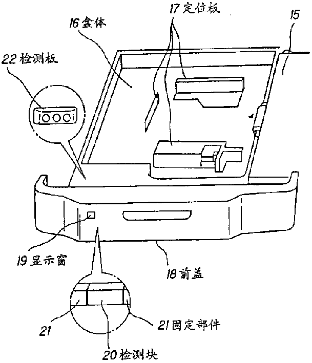
图4为一透视图,其中表示了本发明第一实施例中的输纸盒和输纸装置的主要部件;Fig. 4 is a perspective view showing the main parts of the paper feeding box and the paper feeding device in the first embodiment of the present invention;
图5A为一透视图,其中表示了一个检测块及一个检测板;Fig. 5 A is a perspective view, wherein represented a detection piece and a detection plate;
图5B为沿图5A中的箭头R方向得到的剖视图;Fig. 5B is a sectional view obtained along the arrow R direction in Fig. 5A;
图6A为一剖视图,其中表示了一个光电传感装置的工作状态;Fig. 6 A is a sectional view, wherein has represented the working condition of a photoelectric sensing device;
图6B为图6A所示光电传感装置的电路图;Fig. 6B is a circuit diagram of the photoelectric sensing device shown in Fig. 6A;
图7为一个检测块的展开图;Figure 7 is an expanded view of a detection block;
图8A为一透视图,其中表示了本发明第二实施例中的检测块与检测板;Fig. 8A is a perspective view, which shows the detection block and the detection board in the second embodiment of the present invention;
图8B为沿图8A中箭头S方向得到的剖视图;Fig. 8B is a cross-sectional view obtained along the arrow S direction in Fig. 8A;
图9A为一透视图,其中表示了本发明第三实施例中的检测块与检测板;Fig. 9A is a perspective view, which shows the detection block and the detection board in the third embodiment of the present invention;
图9B为沿图9A中箭头T方向得到的剖视图,其中检测块固定在C′段处;Fig. 9B is a cross-sectional view obtained along the arrow T direction in Fig. 9A, wherein the detection block is fixed at section C';
图9C为沿图9A中箭头T方向得到的剖视图,其中检测块固定在C段处;Fig. 9C is a cross-sectional view obtained along the arrow T direction in Fig. 9A, wherein the detection block is fixed at section C;
图10A为一透视图,其中表示了本发明第四实施例中的检测块;FIG. 10A is a perspective view showing a detection block in a fourth embodiment of the present invention;
图10B为沿图10A中箭头U方向得到的正视图,其中表示了检测块在被移动前的状态;Figure 10B is a front view obtained along the direction of arrow U in Figure 10A, wherein the state of the detection block before being moved is shown;
图10C为沿图10A中的箭头U方向获得的正视图,其中表示了检测块在被移动后的状态;Figure 10C is a front view obtained along the arrow U direction in Figure 10A, wherein the state of the detection block after being moved is shown;
图11A为一透视图,其中表示了本发明第五实施例中的检测块;Fig. 11A is a perspective view, which shows the detection block in the fifth embodiment of the present invention;
图11B为沿图11A中箭头V方向得到的正视图,其中表示了检测块在被翻转前的状态;Fig. 11B is a front view obtained along the arrow V direction in Fig. 11A, wherein the state of the detection block before being turned over is shown;
图11C为沿图11A中的箭头V方向获得的正视图,其中表示了检测块在被翻转后的状态;Figure 11C is a front view obtained along the direction of arrow V in Figure 11A, wherein the state of the detection block after being turned over is shown;
图12A为一透视图,其中表示了本发明第六实施例中的检测块;FIG. 12A is a perspective view showing a detection block in a sixth embodiment of the present invention;
图12B为沿图12A中箭头W方向得到的剖视图;Figure 12B is a cross-sectional view obtained along the arrow W direction in Figure 12A;
图13A为一透视图,其中表示了将第一和第六实施例组合而成的一种本发明实施例;Fig. 13A is a perspective view showing an embodiment of the present invention in which the first and sixth embodiments are combined;
图13B为沿图13A的箭头X方向获得的剖视图。FIG. 13B is a cross-sectional view taken along the arrow X direction of FIG. 13A .
以下将借助于附图详细叙述本发明的各实施例。其中,图2至图5A、5B表示的是本发明的第一实施例。图2和图3表示了一种光电复印机。图4表示了安在该复印机上的本实施例的输纸装置。图5A和5B表示了这种输纸装置的主要部件。Embodiments of the present invention will be described in detail below with reference to the accompanying drawings. Among them, Fig. 2 to Fig. 5A, 5B represent the first embodiment of the present invention. 2 and 3 show a photocopier. Fig. 4 shows the paper feeding device of this embodiment installed on the copying machine. 5A and 5B show the main parts of this paper feeder.
如图2、3所示,在复印机顶部设置有一个原稿台面1。在原稿台面1的下方设置了一个发光元件2。该发光元件2包括一个在照亮放在原稿台面1上的原稿的同时对原稿进行扫描的爆光灯3、一组将来自于原稿的光线反射到一个感光鼓4上的反射镜5和一个布置在该反射光路上的透镜6。As shown in Figures 2 and 3, an original table top 1 is provided on the top of the copier. A light emitting element 2 is provided below the document table 1 . The light emitting element 2 includes an exposure lamp 3 for scanning the original while illuminating the original placed on the original table 1, a set of reflectors 5 for reflecting light from the original onto a photosensitive drum 4, and an arrangement Lens 6 on the reflected light path.
在感光鼓4的外缘设置了一个以某预定电压对感光鼓表面充电的主充电器7、一个使感光鼓4上形成的隐影显影的显影装置8、一个将感光鼓4的表面上已着墨粉的影象转印到复印纸上的转印充电器9、一个用于收集感光鼓表面上的残留墨粉的清洁装置10以及类似的部件。在相对于感光鼓4的进纸侧设置有一个用于在预定时刻输送纸张的定时辊11和用于与定时辊11同步地向感光鼓4输送纸张的输纸装置12。在感光鼓4的另一侧也就是在排纸的一侧设置有一个将转印到复印纸上的已着墨粉的影象定影的定影装置13。On the outer edge of the photosensitive drum 4, a main charger 7 for charging the surface of the photosensitive drum with a predetermined voltage, a developing device 8 for developing the shadow formed on the photosensitive drum 4, and a developing device 8 for charging the surface of the photosensitive drum 4 A transfer charger 9 for transferring a toner-coated image onto copy paper, a cleaning device 10 for collecting residual toner on the surface of the photosensitive drum, and the like. On the paper feeding side with respect to the photosensitive drum 4 are provided a timing roller 11 for feeding paper at a predetermined timing and a
以下将描述这种结构的复印机的复印过程。当接通电源开关(图中未示)时,预热程序开始。预热过程一结束,控制板上的复印启动开关即被触发,于是发光元件2的爆光灯3对放置在原稿台面1上的原稿进行扫描。从原稿上反射的光通过一组反射镜5和透镜6被引向将要被感光的感光鼓4上,此时在主充电器7以某预定电压的充电作用下在感光鼓4上形成一静电隐影。The copying process of the copying machine of this structure will be described below. When the power switch (not shown) is turned on, the preheating program starts. As soon as the preheating process is over, the copy start switch on the control board is triggered, so the flashlight 3 of the light emitting element 2 scans the original placed on the original table 1 . The light reflected from the original is guided to the photosensitive drum 4 to be photosensitive through a set of mirrors 5 and lenses 6. At this time, a static electricity is formed on the photosensitive drum 4 under the charging action of the main charger 7 with a predetermined voltage. hidden.
而后,在显影装置8供给的墨粉的作用下静电隐影即被显露出来。在感光鼓4表面上着墨粉的影象在转印充电器9的作用下被转印到从输纸装置12输送的复印纸上,该转印的已着墨粉的影象在定影装置13的作用下被定影到纸张上。于是,在复印纸上产生与原稿影象相同的复印影象。以上的复印程序是由装在复印机机体内的一个带有微机的控制器控制的。Then, the electrostatic shadow is revealed by the action of the toner supplied from the developing device 8 . The toner-coated image on the surface of the photosensitive drum 4 is transferred to the copy paper conveyed from the
在具有上述结构并按照上述程序工作的复印机中,输纸装置12包括一组相对于输纸机构15垂直布置的送纸盒14。各送纸盒14容纳多张纸张。输纸机构15与定时辊11同步工作,从而使纸盒中的纸张被一张一张地分开送到感光鼓4上。该实施例的特征在于设置有用于检测放在送纸盒14内的纸张的尺寸的装置及显示该尺寸的装置。In the copier having the above structure and operating according to the above procedure, the
如图4中专门表示的那样,各送纸盒14有一个盒体16,即一个可容放不同尺寸纸张的纸盘。在盒体16中有若干用于固定纸张位置的定位板17。在面向复印机外侧的前部设置了一个前盖18。在该前盖的一侧有一个显示窗19。该显示窗用于显示纸张的尺寸。一个用于检测纸张尺寸的检测块20被放置在该前盖18内侧的后侧以便面向显示窗19并与一个固定部件21配合固定。同时,一个用于检测纸张尺寸的检测板22被放置在前盖18的内侧并位于检测块20的下方以使其与检测块20对置。As specifically shown in FIG. 4, each feed cassette 14 has a cassette body 16, ie, a paper tray that accommodates different sizes of paper. There are several positioning plates 17 for fixing the position of the paper in the box body 16 . A
盒体16的结构保证盒体可相对于复印机机体拉入拉出并可容纳不同尺寸的纸张如B5、A4、B4和A3的纸张。所设置的定位隔板17可相应于所容纳的纸张的尺寸而部分移动。当盒体16被拉出复印机机体时,可以调整定位隔板17的位置,并装上纸。当盒体16被插入到复印机机体内时,可通过输纸机构15输送纸盒中的纸张。The structure of the box body 16 ensures that the box body can be pulled in and out relative to the copier body and can accommodate paper of different sizes such as B5, A4, B4 and A3 paper. The positioning partition 17 is provided to be partially movable corresponding to the size of the accommodated paper. When the box body 16 is pulled out of the copier body, the position of the positioning partition 17 can be adjusted and the paper loaded. When the box body 16 is inserted into the body of the copier, the paper in the paper box can be transported by the
图5A和5B中表示了检测块20和检测板22。图5B是沿图5A的箭头R方向得到的剖视图。在该图中,画有影线的部分为带有诸如B5、A4、B4、A3等指示标志的断面。如图5A、5B所示,一组光电传感器,即图中三个光电传感器23a、23b和23c被布置在检测板22上用于检测纸张尺寸。这些光电传感器23a、23b和23c上各有一个如图6B所示的发光元件p和一个受光元件q。The
检测块20是由一个规则的多边棱镜,特别是由一个正方棱镜制成的。在该棱镜的各面上均带有若干信号发生元件24。这些信号发生元件24用于响应于传感器23a、23b和23c中的任一传感器而发生信号。该检测块20与一个固定部件21连接并由其可拆分地固定。The
图6A表示了上述实施例中的传感器23a、23b和23c的工作原理。由于来自于传感器23a的光线进入了检测块20的孔中因而不被反射,故由图6B所示电路图中可以看出信号水平变为VD。来自传感器23b的光线被检测块20的表面反射从而使信号水平变为GND。通过对来自光电传感器的这些信号的组合即可进行尺寸检测。Fig. 6A shows the working principle of the
图7是检测块20的展开图。如图所示,在检测块20上的‘g′区域中孔的分布与‘f′区域的孔的分布刚好相反,由此可提高被检测纸张尺寸的数目。标号23a至23c为光电传感器,带影线的部分‘e′表示检测块20上带有孔的指示断面,而空白部分‘h′则表示不带孔的断面。FIG. 7 is an expanded view of the
在采用这种结构的输纸装置的情况下,复印机使用者将纸张放入送纸盒14中并将检测块20放进与盒内纸张尺寸一致的固定部件21中。这样设定后,面向检测块20的信号发生元件24的检测板22上的光电传感器23a、23b和23c检测来自于信号发生元件24的信号,进而检测送纸盒14内的纸张尺寸。此外,将检测块20沿图5A中箭头‘a′的方向翻转180°,则可改变面向信号发生元件24的检测板22上的传感器的组合方式,因而可增加被检测尺寸的种类数。In the case of a paper feeding device with this structure, the user of the copier puts paper into the paper feeding box 14 and puts the
更特殊的一种方式是,使检测块20的信号发生元件24相对于一排传感器23以一预定的方式排列,例如以交替的或类似的方式排列。例如,假定对于A4号纸,检测块20上的信号发生元件24的排列是使传感器23a和23c接通,而对于A3号纸,检测块20上的信号发生元件24的排列则仅使传感器23b可被检测到。A more specific way is to arrange the signal generating elements 24 of the
现在,假定A4纸被放进送纸盒14中。在此情况下,如果安上检测块20使得信号发生元件24的排列与该纸张尺寸一致,则此时A4的指示标志将从显示窗19中显示出来。接着,放入A3纸,由于检测块20被翻转了180°,因而信号发生元件24的排列使得只能对传感器23b作用,所以指示标志A3从显示窗19中显示出来。此外,检测块20的其他面可以用于适合于B系列尺寸的信号发生元件24的排列,因而也可以显示出诸如B5、B4等类似的指示。Now, assume that A4 paper is set in the paper feed cassette 14 . In this case, if the
因此,根据本实施例,通过固定部件21将一个正方棱镜型的检测块20固定在不同的方位,同时将一组传感器23a、23b和23c设置在检测块20的对面,从而可以检测出对应于检测块20的设置状态的纸张尺寸。在该结构中,送纸盒14中的纸张的尺寸是通过传感器23a、23b和23c相应于检测块20在固定部件21中的固定位置而产生的信号从显示窗19中显示出来的。因此,可以用光学方法获得纸张尺寸检测部件及输纸装置12的指示部分的区域,从而减小这些部件的尺寸。Therefore, according to this embodiment, a square prism-
图8A、8B中表示了本发明第二实施例中的检测块20和检测板22。图8B是沿图8A的箭头S方向得到的剖视图。该实施例中的输纸装置12的总体结构同于图4所示的第一实施例,因而略去重复叙述。在该实施例中,检测块20上置有一根可转动的轴25和一个与该轴同轴的轮毂状的转动限制凸缘26,由此可使检测块20转动并被限位。8A and 8B show the
在该方案中,在固定部件的一侧设置有一个固定安装件21a,用于安装检测块20。在该固定安装件上与检测块20相对的一端置有一个转动限制凸缘26。在该固定部件的另一侧设置有一个检测块20的移位装置21b。该移位装置21b包括一个与轴25同轴的弹簧27,轴25在弹簧的作用下沿图8A中的箭头b的方向移动。In this solution, a fixed installation part 21a is provided on one side of the fixed part for installing the
在上述结构中,当检测块20在反向于弹簧27的作用力的作用下沿图8A中的箭头b′的方向移动时,在转动限制凸缘26与固定安装件21a之间的受压定位状态被解除,从而检测块20可沿箭头c方向转动。而后,当检测块20在弹簧27的推力的作用下沿箭头b移动时,检测块20又通过转动限制凸缘26与固定安装件21a之间的接合而被定位,由此可以设定纸张尺寸。In the above structure, when the
这样,在该实施例中,由于为检测块20设置了转动限制凸缘26,而且作为弹性元件的弹簧27作为固定部件的另一部分被置于移位装置21b和检测块20之间,因而检测块20被压向作为固定部件的一侧的固定安装件21a,从而使检测块20的转动被转动限制凸缘26限制。当检测块20在反向于弹簧27的弹力的作用下被移动时,检测块20被移动到与转动限制凸缘26脱开的位置上。在该位置,检测块20可相对于检测板22上的传感器23a、23b、…转动,从而可改变检测块上与传感器相对的面。因此,在换纸时可减少安装和拆下检测块的步骤,从而简化了纸张尺寸的设定操作。In this way, in this embodiment, since the
图9A、9B和9C表示了本发明第三实施例中的检测块20和检测板22。图9B和9C均为沿图9A中的箭头T方向得到的剖视图。图9B表示的是检测块20固定在位置c′处的状态,而图9C表示的是检测块20固定在位置c处的状态。用在该实施例中的输纸装置12的总体结构同于图4所示的第一实施例,因而略去重复叙述。在该实施例中,检测块20被用来从一侧移到另一侧,由此可减少占有的空间,因而可通过少量的移动检测到多种纸张尺寸。9A, 9B and 9C show the
也就是说,在该实施例中,用沿箭头d和d′方向轴向移动检测块20的方式取代了转动检测块20的侧面的方式,由此将检测块20定位在一个第一位置A与一个第二位置B之间。即,在每一位置上都可以检测一种纸张尺寸。为此目的设置了定位槽28a、28b和29a,29b,用于使检测块20分别固定在相对于检测板22上的传感器处在第一位置A和第二位置B处。第一位置A和第二位置B可根据传感器23a、23b和23c之间的间距相互移动。That is to say, in this embodiment, the method of rotating the side of the
特别是,在检测块20的两轴向端设置了凸缘30a和30b,而在固定安装件31上制有定位槽28a、28b、29a和29b,用于使检测块20定位。在该结构中,可以沿着箭头d、d′的方向移动检测块20,使检测块20设定在位置c′即检测块20卡在定位槽28a和28b中或设定在位置c即检测块20卡在定位槽29a和29b中。在每个位置上都可以用手转动该检测块从而设定不同的尺寸状态,所以这种结构与只能在一个固定位置上转动检测块的结构相比,所能检测纸张尺寸的数目为后者的两倍。In particular,
这样,在本实施例中,由于在检测块20的两端设置了凸缘30a、30b和在固定安装件31上制造了定位槽28a、28b、29a和29b,因而可通过在较小的空间内小量移动检测块达到检测多种纸张尺寸的目的。In this way, in this embodiment, since the
图10A、10B和10C表示本发明第四实施例的检测块20。图10B和10C均为沿图10A中的箭头U方向得到的剖视图。图10B表示的是检测块20移动前的状态,而图10C表示的是检测块20移动后的状态。用在该实施例中的输纸装置12的总体结构同于图4所示的第一实施例,因而略去重复叙述。在该实施例中,检测块20被用来从一侧移到另一侧,由此可减少占有的空间,因而可通过少量的移动来检测并显示多种纸张尺寸。10A, 10B and 10C show a
也就是说,在该实施例中,检测块20除了具有上述第三实施例中的结构外还在其一个轴端设置了纸张尺寸指示标志32。当检测块20从一侧向另一侧小量移动时,则选自于多个纸张尺寸指示标志中的一个指示标志通过形成在前盖18上的显示窗19而显示出来。因此,采用本实施例的结构可简化纸张尺寸的设定过程并可在较小的空间内检测出多种纸张尺寸。That is to say, in this embodiment, in addition to the structure of the third embodiment above, the
图11A、11B和11C表示本发明第五实施例的检测块20。图11B和11C均为沿图11A中的箭头V方向得到的剖视图。图11B表示的是检测块20被翻转前的状态,而图11C表示的是检测块20被翻转后的状态。用在该实施例中的输纸装置12的总体结构同于图4所示的第一实施例,因而略去重复叙述。在该实施例中,在检测块20的两轴端设置了纸张尺寸指示标志32,因而即使在检测块20为更换尺寸而被翻面时也可以通过一个显示窗19显示出尺寸指示标志。11A, 11B and 11C show the
也就是说,通过在图5A和5B所示的检测块20上增加纸张尺寸指示标志32,可使检测块20检测到的纸张尺寸通过送纸盒的前盖18上的显示窗19而显示出来。因此,这种结构不但可在较小的空间内检测多种纸张尺寸而且可简化纸张尺寸的设定过程。That is to say, by adding the paper
图12A和12B表示本发明第六实施例的检测块20。图12B为沿图12A中的箭头W方向得到的剖视图。用在该实施例中的输纸装置12的总体结构同于图4所示的第一实施例,因而略去重复叙述。在该实施例中,检测块20的结构可减小其体积,并且即使在检测块20为更换尺寸而被翻面时也可以通过一个显示窗19显示出尺寸指示标志。12A and 12B show a
也就是说,通过在图5A和5B所示检测块20的中部增加纸张尺寸指示标志32,可使检测块20检测到的纸张尺寸通过送纸盒的前盖18上的显示窗19显示出来。此外,在检测块20上的同一区域设置了两个上下相反的指示标志并且当该同一区域从一侧翻到另一侧时即可用于显示纸张的尺寸。这样,若采用本实施例就可检测和显示多种纸张尺寸,同时又可简化纸张尺寸设定过程并减少检测所需要的空间。That is to say, by adding a paper
图13A为一透视图,其中表示了一个检测块20和一个检测板22。该透视图所对应的是将第一和第六实施例组合而成的一个实施例。为简化结构,下面的几何形状采用了在图4所示的输纸装置12上组合这些元件的方式。即,对于检测块20而言,其插入和取出的方向、移动的方向、纸张尺寸检测的方位以及被检测的纸张尺寸的指示方位都不相同。更具体的是,输纸装置12包括一个输纸机构15、定位隔板17、一检测块20、一个定位部件21、一个与检测块20对置的检测板22和一个在不同于检测块20的检测面的侧面上的显示窗19。当把检测块20放入固定部件21中时,几何形状应当保证检测块20沿水平方向移动,检测块的检测面指向下方;二者的方向均不同于显示窗19所面对的前方。图13B是沿图13A的箭头X方向得到的剖视图。FIG. 13A is a perspective view in which a
具体地说,就是在图5A和5B所示的检测块20上加上了图13A和13B或图12A和12B所示的纸张尺寸指示标志32,这种简单的结构使得能够通过送纸盒的前盖18上的显示窗19显示出由检测块20检测到的纸张尺寸。Specifically, on the
如上所述,根据本发明,由于检测装置是由规则的多边棱镜构成的,因而可以在通过光学方法探查纸张尺寸检测装置的区域的同时减小纸张尺寸检测装置。此外还可以增加被检测的纸张尺寸的种类。As described above, according to the present invention, since the detection means is constituted by regular polygonal prisms, it is possible to reduce the size of the paper size detection means while optically detecting the area of the paper size detection means. In addition, the types of paper sizes to be detected can be increased.
此外,根据本发明,由于检测块可转动到不同的方位并固定在设定位置上,因而可简化纸张尺寸的设定过程。在本发明的另一种方案中,由于检测块可沿其轴向方向移动,因而可在较小的空间内检测多种纸张尺寸。Furthermore, according to the present invention, since the detection block can be rotated to different orientations and fixed at a set position, the paper size setting process can be simplified. In another solution of the present invention, since the detection block can move along its axial direction, various paper sizes can be detected in a small space.
Claims (3)
Applications Claiming Priority (2)
| Application Number | Priority Date | Filing Date | Title |
|---|---|---|---|
| JP04515595A JP3148549B2 (en) | 1995-03-06 | 1995-03-06 | Paper feeder |
| JP45155/95 | 1995-03-06 |
Publications (2)
| Publication Number | Publication Date |
|---|---|
| CN1159617A CN1159617A (en) | 1997-09-17 |
| CN1092811C true CN1092811C (en) | 2002-10-16 |
Family
ID=12711386
Family Applications (1)
| Application Number | Title | Priority Date | Filing Date |
|---|---|---|---|
| CN96104038A Expired - Fee Related CN1092811C (en) | 1995-03-06 | 1996-03-06 | Paper feeder |
Country Status (3)
| Country | Link |
|---|---|
| US (1) | US5676370A (en) |
| JP (1) | JP3148549B2 (en) |
| CN (1) | CN1092811C (en) |
Families Citing this family (10)
| Publication number | Priority date | Publication date | Assignee | Title |
|---|---|---|---|---|
| US5884132A (en) * | 1997-10-20 | 1999-03-16 | Eastman Kodak Company | Cabinetry with shape-based indicators |
| USD415192S (en) * | 1998-06-18 | 1999-10-12 | Hewlett-Packard Company | Feeder with tray for a document printer |
| KR100388995B1 (en) * | 2000-12-29 | 2003-06-25 | 삼성전자주식회사 | Paper size recognizing device for image forming appratus |
| KR100444593B1 (en) * | 2002-07-04 | 2004-08-16 | 삼성전자주식회사 | Auto paper suppling apparatus of printer |
| TW588545B (en) * | 2002-09-16 | 2004-05-21 | Avision Inc | Sheet-size detecting mechanism |
| JP2007214676A (en) * | 2006-02-07 | 2007-08-23 | Canon Inc | Image forming apparatus |
| JP5477355B2 (en) * | 2011-10-03 | 2014-04-23 | コニカミノルタ株式会社 | Paper feeder |
| JP6324087B2 (en) * | 2014-01-28 | 2018-05-16 | キヤノン株式会社 | Image forming apparatus |
| US9561920B1 (en) | 2015-10-01 | 2017-02-07 | Xerox Corporation | Media supply tray having multi-color exterior light indicating different media loading conditions |
| CN107934603B (en) * | 2017-10-16 | 2019-08-16 | 西安理工大学 | A kind of design method of sheet-fed sheet positioning paper feeding plate |
Family Cites Families (6)
| Publication number | Priority date | Publication date | Assignee | Title |
|---|---|---|---|---|
| JPH0735915B2 (en) * | 1985-07-12 | 1995-04-19 | 三洋電機株式会社 | Heat exchange unit |
| JP2719366B2 (en) * | 1988-10-24 | 1998-02-25 | 三田工業株式会社 | Tester for paper cassette size detector |
| JP2630471B2 (en) * | 1989-08-22 | 1997-07-16 | 富士通電装 株式会社 | Transformer inrush current prevention circuit |
| JPH04327431A (en) * | 1991-04-25 | 1992-11-17 | Ricoh Co Ltd | Sheet size display device |
| US5839047A (en) * | 1992-01-28 | 1998-11-17 | Fujitsu Limited | Sheet-size detection mechanism for sheet cassettes and image-forming-apparatus using the same |
| US5539512A (en) * | 1995-07-28 | 1996-07-23 | Hewlett-Packard Company | Multi-range media size visual indicator |
-
1995
- 1995-03-06 JP JP04515595A patent/JP3148549B2/en not_active Expired - Fee Related
-
1996
- 1996-02-16 US US08/602,454 patent/US5676370A/en not_active Expired - Lifetime
- 1996-03-06 CN CN96104038A patent/CN1092811C/en not_active Expired - Fee Related
Also Published As
| Publication number | Publication date |
|---|---|
| JPH08239125A (en) | 1996-09-17 |
| US5676370A (en) | 1997-10-14 |
| CN1159617A (en) | 1997-09-17 |
| JP3148549B2 (en) | 2001-03-19 |
Similar Documents
| Publication | Publication Date | Title |
|---|---|---|
| CN1214293C (en) | Image forming apparatus | |
| CN1092811C (en) | Paper feeder | |
| CN102193190B (en) | Mounting structure of a mounted component, light scanning device, and image forming apparatus | |
| KR20150049264A (en) | Adjustment device of imaging unit, imaging unit, and image reading apparatus including the same | |
| JPH04338034A (en) | Paper tray of flexibility | |
| CN1012763B (en) | Split scanning copier | |
| GB2180794A (en) | An image forming apparatus | |
| CN100344519C (en) | Paper transfer mechanism | |
| CN1469204A (en) | Imaging apparatus | |
| CN1481144A (en) | Imaging device including image reader | |
| CN1070424C (en) | Image forming system with device for confirming number of sheets | |
| CN1200322C (en) | Image formation equipment | |
| CN1161478A (en) | image forming device | |
| CN100558618C (en) | Recording medium discharge mechanism and image forming apparatus having same | |
| US5648843A (en) | Automatic duplex image forming apparatus having an adjusting driving mechanism | |
| CN1174290C (en) | imaging device | |
| JP2002174788A (en) | Optical scanning device of image forming apparatus and image forming apparatus using the same | |
| CN1760767A (en) | Paper arrangement device and electrophotographic image forming apparatus having the same | |
| CN1794779A (en) | Image forming apparatus | |
| JP2526254Y2 (en) | Copy machine charger device | |
| KR970003759Y1 (en) | Spring tension regulator for sheet cassette | |
| KR0122615Y1 (en) | Copying paper sorting device of electronic duplicator | |
| JPH0731248Y2 (en) | Image forming device | |
| JP4154273B2 (en) | Discharge shifter mechanism and image forming apparatus | |
| JP2002211822A (en) | Image forming device |
Legal Events
| Date | Code | Title | Description |
|---|---|---|---|
| C06 | Publication | ||
| PB01 | Publication | ||
| C10 | Entry into substantive examination | ||
| SE01 | Entry into force of request for substantive examination | ||
| C14 | Grant of patent or utility model | ||
| GR01 | Patent grant | ||
| C17 | Cessation of patent right | ||
| CF01 | Termination of patent right due to non-payment of annual fee |
Granted publication date: 20021016 Termination date: 20140306 |