CN109299518B - A Calculation Method of Pressure Loss of Series R Type Automobile Shock Absorber - Google Patents
A Calculation Method of Pressure Loss of Series R Type Automobile Shock Absorber Download PDFInfo
- Publication number
- CN109299518B CN109299518B CN201810998312.4A CN201810998312A CN109299518B CN 109299518 B CN109299518 B CN 109299518B CN 201810998312 A CN201810998312 A CN 201810998312A CN 109299518 B CN109299518 B CN 109299518B
- Authority
- CN
- China
- Prior art keywords
- shock absorber
- pressure loss
- resistance
- series
- automobile shock
- Prior art date
- Legal status (The legal status is an assumption and is not a legal conclusion. Google has not performed a legal analysis and makes no representation as to the accuracy of the status listed.)
- Active
Links
Images


Classifications
-
- G—PHYSICS
- G06—COMPUTING OR CALCULATING; COUNTING
- G06F—ELECTRIC DIGITAL DATA PROCESSING
- G06F30/00—Computer-aided design [CAD]
- G06F30/10—Geometric CAD
- G06F30/15—Vehicle, aircraft or watercraft design
-
- B—PERFORMING OPERATIONS; TRANSPORTING
- B60—VEHICLES IN GENERAL
- B60G—VEHICLE SUSPENSION ARRANGEMENTS
- B60G13/00—Resilient suspensions characterised by arrangement, location or type of vibration dampers
- B60G13/02—Resilient suspensions characterised by arrangement, location or type of vibration dampers having dampers dissipating energy, e.g. frictionally
- B60G13/06—Resilient suspensions characterised by arrangement, location or type of vibration dampers having dampers dissipating energy, e.g. frictionally of fluid type
- B60G13/08—Resilient suspensions characterised by arrangement, location or type of vibration dampers having dampers dissipating energy, e.g. frictionally of fluid type hydraulic
-
- B—PERFORMING OPERATIONS; TRANSPORTING
- B60—VEHICLES IN GENERAL
- B60G—VEHICLE SUSPENSION ARRANGEMENTS
- B60G13/00—Resilient suspensions characterised by arrangement, location or type of vibration dampers
- B60G13/16—Resilient suspensions characterised by arrangement, location or type of vibration dampers having dynamic absorbers as main damping means, i.e. spring-mass system vibrating out of phase
- B60G13/18—Resilient suspensions characterised by arrangement, location or type of vibration dampers having dynamic absorbers as main damping means, i.e. spring-mass system vibrating out of phase combined with energy-absorbing means
-
- B—PERFORMING OPERATIONS; TRANSPORTING
- B60—VEHICLES IN GENERAL
- B60G—VEHICLE SUSPENSION ARRANGEMENTS
- B60G15/00—Resilient suspensions characterised by arrangement, location or type of combined spring and vibration damper, e.g. telescopic type
- B60G15/02—Resilient suspensions characterised by arrangement, location or type of combined spring and vibration damper, e.g. telescopic type having mechanical spring
- B60G15/06—Resilient suspensions characterised by arrangement, location or type of combined spring and vibration damper, e.g. telescopic type having mechanical spring and fluid damper
-
- F—MECHANICAL ENGINEERING; LIGHTING; HEATING; WEAPONS; BLASTING
- F15—FLUID-PRESSURE ACTUATORS; HYDRAULICS OR PNEUMATICS IN GENERAL
- F15B—SYSTEMS ACTING BY MEANS OF FLUIDS IN GENERAL; FLUID-PRESSURE ACTUATORS, e.g. SERVOMOTORS; DETAILS OF FLUID-PRESSURE SYSTEMS, NOT OTHERWISE PROVIDED FOR
- F15B21/00—Common features of fluid actuator systems; Fluid-pressure actuator systems or details thereof, not covered by any other group of this subclass
- F15B21/008—Reduction of noise or vibration
-
- F—MECHANICAL ENGINEERING; LIGHTING; HEATING; WEAPONS; BLASTING
- F16—ENGINEERING ELEMENTS AND UNITS; GENERAL MEASURES FOR PRODUCING AND MAINTAINING EFFECTIVE FUNCTIONING OF MACHINES OR INSTALLATIONS; THERMAL INSULATION IN GENERAL
- F16F—SPRINGS; SHOCK-ABSORBERS; MEANS FOR DAMPING VIBRATION
- F16F9/00—Springs, vibration-dampers, shock-absorbers, or similarly-constructed movement-dampers using a fluid or the equivalent as damping medium
- F16F9/10—Springs, vibration-dampers, shock-absorbers, or similarly-constructed movement-dampers using a fluid or the equivalent as damping medium using liquid only; using a fluid of which the nature is immaterial
- F16F9/14—Devices with one or more members, e.g. pistons, vanes, moving to and fro in chambers and using throttling effect
- F16F9/16—Devices with one or more members, e.g. pistons, vanes, moving to and fro in chambers and using throttling effect involving only straight-line movement of the effective parts
- F16F9/18—Devices with one or more members, e.g. pistons, vanes, moving to and fro in chambers and using throttling effect involving only straight-line movement of the effective parts with a closed cylinder and a piston separating two or more working spaces therein
- F16F9/19—Devices with one or more members, e.g. pistons, vanes, moving to and fro in chambers and using throttling effect involving only straight-line movement of the effective parts with a closed cylinder and a piston separating two or more working spaces therein with a single cylinder and of single-tube type
-
- F—MECHANICAL ENGINEERING; LIGHTING; HEATING; WEAPONS; BLASTING
- F16—ENGINEERING ELEMENTS AND UNITS; GENERAL MEASURES FOR PRODUCING AND MAINTAINING EFFECTIVE FUNCTIONING OF MACHINES OR INSTALLATIONS; THERMAL INSULATION IN GENERAL
- F16F—SPRINGS; SHOCK-ABSORBERS; MEANS FOR DAMPING VIBRATION
- F16F9/00—Springs, vibration-dampers, shock-absorbers, or similarly-constructed movement-dampers using a fluid or the equivalent as damping medium
- F16F9/32—Details
- F16F9/34—Special valve constructions; Shape or construction of throttling passages
-
- G—PHYSICS
- G06—COMPUTING OR CALCULATING; COUNTING
- G06F—ELECTRIC DIGITAL DATA PROCESSING
- G06F17/00—Digital computing or data processing equipment or methods, specially adapted for specific functions
- G06F17/10—Complex mathematical operations
- G06F17/11—Complex mathematical operations for solving equations, e.g. nonlinear equations, general mathematical optimization problems
- G06F17/13—Differential equations
-
- G—PHYSICS
- G06—COMPUTING OR CALCULATING; COUNTING
- G06F—ELECTRIC DIGITAL DATA PROCESSING
- G06F30/00—Computer-aided design [CAD]
- G06F30/20—Design optimisation, verification or simulation
-
- F—MECHANICAL ENGINEERING; LIGHTING; HEATING; WEAPONS; BLASTING
- F16—ENGINEERING ELEMENTS AND UNITS; GENERAL MEASURES FOR PRODUCING AND MAINTAINING EFFECTIVE FUNCTIONING OF MACHINES OR INSTALLATIONS; THERMAL INSULATION IN GENERAL
- F16F—SPRINGS; SHOCK-ABSORBERS; MEANS FOR DAMPING VIBRATION
- F16F2230/00—Purpose; Design features
- F16F2230/24—Detecting or preventing malfunction, e.g. fail safe
-
- F—MECHANICAL ENGINEERING; LIGHTING; HEATING; WEAPONS; BLASTING
- F16—ENGINEERING ELEMENTS AND UNITS; GENERAL MEASURES FOR PRODUCING AND MAINTAINING EFFECTIVE FUNCTIONING OF MACHINES OR INSTALLATIONS; THERMAL INSULATION IN GENERAL
- F16F—SPRINGS; SHOCK-ABSORBERS; MEANS FOR DAMPING VIBRATION
- F16F2238/00—Type of springs or dampers
- F16F2238/02—Springs
- F16F2238/022—Springs leaf-like, e.g. of thin, planar-like metal
-
- F—MECHANICAL ENGINEERING; LIGHTING; HEATING; WEAPONS; BLASTING
- F16—ENGINEERING ELEMENTS AND UNITS; GENERAL MEASURES FOR PRODUCING AND MAINTAINING EFFECTIVE FUNCTIONING OF MACHINES OR INSTALLATIONS; THERMAL INSULATION IN GENERAL
- F16F—SPRINGS; SHOCK-ABSORBERS; MEANS FOR DAMPING VIBRATION
- F16F2238/00—Type of springs or dampers
- F16F2238/02—Springs
- F16F2238/026—Springs wound- or coil-like
-
- G—PHYSICS
- G06—COMPUTING OR CALCULATING; COUNTING
- G06F—ELECTRIC DIGITAL DATA PROCESSING
- G06F2111/00—Details relating to CAD techniques
- G06F2111/06—Multi-objective optimisation, e.g. Pareto optimisation using simulated annealing [SA], ant colony algorithms or genetic algorithms [GA]
-
- G—PHYSICS
- G06—COMPUTING OR CALCULATING; COUNTING
- G06F—ELECTRIC DIGITAL DATA PROCESSING
- G06F2119/00—Details relating to the type or aim of the analysis or the optimisation
- G06F2119/06—Power analysis or power optimisation
-
- G—PHYSICS
- G06—COMPUTING OR CALCULATING; COUNTING
- G06F—ELECTRIC DIGITAL DATA PROCESSING
- G06F2119/00—Details relating to the type or aim of the analysis or the optimisation
- G06F2119/14—Force analysis or force optimisation, e.g. static or dynamic forces
-
- Y—GENERAL TAGGING OF NEW TECHNOLOGICAL DEVELOPMENTS; GENERAL TAGGING OF CROSS-SECTIONAL TECHNOLOGIES SPANNING OVER SEVERAL SECTIONS OF THE IPC; TECHNICAL SUBJECTS COVERED BY FORMER USPC CROSS-REFERENCE ART COLLECTIONS [XRACs] AND DIGESTS
- Y02—TECHNOLOGIES OR APPLICATIONS FOR MITIGATION OR ADAPTATION AGAINST CLIMATE CHANGE
- Y02T—CLIMATE CHANGE MITIGATION TECHNOLOGIES RELATED TO TRANSPORTATION
- Y02T90/00—Enabling technologies or technologies with a potential or indirect contribution to GHG emissions mitigation
Landscapes
- Engineering & Computer Science (AREA)
- Physics & Mathematics (AREA)
- General Physics & Mathematics (AREA)
- Geometry (AREA)
- General Engineering & Computer Science (AREA)
- Theoretical Computer Science (AREA)
- Mathematical Analysis (AREA)
- Computational Mathematics (AREA)
- Mechanical Engineering (AREA)
- Mathematical Optimization (AREA)
- Pure & Applied Mathematics (AREA)
- Evolutionary Computation (AREA)
- Computer Hardware Design (AREA)
- Mathematical Physics (AREA)
- Automation & Control Theory (AREA)
- Aviation & Aerospace Engineering (AREA)
- Data Mining & Analysis (AREA)
- Fluid Mechanics (AREA)
- Analytical Chemistry (AREA)
- Chemical & Material Sciences (AREA)
- Operations Research (AREA)
- Algebra (AREA)
- Databases & Information Systems (AREA)
- Software Systems (AREA)
- Fluid-Damping Devices (AREA)
- Vibration Prevention Devices (AREA)
- Vehicle Body Suspensions (AREA)
Abstract
本发明公开了一种串联R式汽车减振器的压力损失计算方法。该汽车减振器包括车架、弹簧、车轴、液压缸、上油仓、活塞、下油仓、调阻段。调阻段由串联的4路毛细管、电磁阀组成。这4路毛细管都盘成了M型。这4路毛细管分别是毛细管R8、R4、R2、R1;它们分别并联电磁阀VR8、VR4、VR2、VR1。由于缸体内的油性液体的粘性作用,当油性液体流经调阻段时,调节电磁阀VR8、VR4、VR2、VR1的组态SRn即可调节阻尼。本发明提供了R式汽车减振器压力损失的计算方法,达到了减少控制模型不确定性的目的。为改善减振器控制品质提供了理论依据。
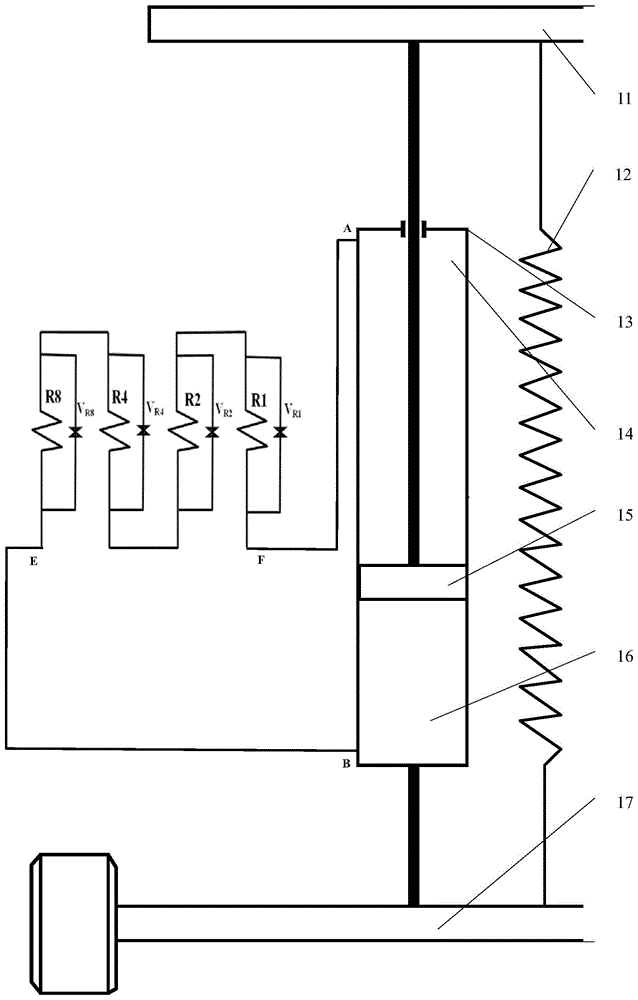
The invention discloses a method for calculating the pressure loss of a serial R-type automobile shock absorber. The automobile shock absorber comprises a vehicle frame, a spring, an axle, a hydraulic cylinder, an upper oil tank, a piston, a lower oil tank and a resistance adjusting section. The resistance adjustment section is composed of 4 capillary tubes and solenoid valves connected in series. These 4-way capillaries are coiled into an M shape. These four capillary tubes are capillary tubes R8, R4 , R2 and R1 respectively; they are connected in parallel with solenoid valves V R8 , VR4 , VR2 and VR1 respectively. Due to the viscosity of the oily liquid in the cylinder, when the oily liquid flows through the resistance adjusting section, the damping can be adjusted by adjusting the configuration S Rn of the solenoid valves V R8 , V R4 , V R2 , and V R1 . The invention provides a calculation method for the pressure loss of the R-type automobile shock absorber, and achieves the purpose of reducing the uncertainty of the control model. It provides a theoretical basis for improving the control quality of the shock absorber.
Description
技术领域technical field
本发明涉及液压式汽车减振器领域,尤其涉及一种串联R式汽车减振器的压力损失计算方法。The invention relates to the field of hydraulic automobile shock absorbers, in particular to a method for calculating pressure loss of series R-type automobile shock absorbers.
背景技术Background technique
汽车的减振方式主要有液压式、气压式、电磁式。液压式是目前用得最广泛的汽车减振方式。The vibration reduction methods of automobiles mainly include hydraulic type, pneumatic type and electromagnetic type. The hydraulic type is currently the most widely used vehicle vibration reduction method.
图1为现有串联R式汽车减振器的结构示意图,该串联R式汽车减振器的工作原理,请参见专利号为ZL 201110446289.6、专利名称为一种串联毛细管可变阻尼的汽车减振器。Figure 1 is a structural schematic diagram of the existing series R-type automobile shock absorber. For the working principle of the series R-type automobile shock absorber, please refer to the patent No. ZL 201110446289.6, and the patent name is a kind of automobile shock absorber with series capillary variable damping device.
该汽车减振器包括车架、弹簧、车轴、液压缸、上油仓、活塞、下油仓、调阻段。The automobile shock absorber comprises a vehicle frame, a spring, an axle, a hydraulic cylinder, an upper oil tank, a piston, a lower oil tank and a resistance adjusting section.
调阻段由电磁阀、串联的4路毛细管组成。这4路毛细管都盘成了M型。这4路毛细管分别是毛细管R8、R4、R2、R1;它们分别并联电磁阀VR8、VR4、 VR2、VR1。调节电磁阀VR8、VR4、VR2、VR1的组态SRn即可调节阻尼。The resistance adjustment section is composed of a solenoid valve and 4 capillary tubes connected in series. These 4-way capillaries are coiled into an M shape. The four capillary tubes are capillary tubes R8, R4, R2 and R1 respectively; they are connected in parallel with solenoid valves V R8 , V R4 , V R2 and VR1 respectively. The damping can be adjusted by adjusting the configuration S Rn of the solenoid valves V R8 , VR4 , VR2 , and VR1 .
该汽车减振器工作原理是,当车架和车轴之间产生相对运动时,活塞会相应的产生或上或下的移动,此时液压缸内的油性液体会经过上油仓油口、下油仓油口之间的调阻段;进而从上油仓流向下油仓,或者从下油仓流向上油仓。The working principle of the automobile shock absorber is that when there is relative movement between the frame and the axle, the piston will move up or down accordingly, and the oily liquid in the hydraulic cylinder will pass through the oil port of the upper oil tank, the lower The resistance adjustment section between the oil ports of the oil tank; and then flows from the upper oil tank to the lower oil tank, or flows from the lower oil tank to the upper oil tank.
由于缸体内的油性液体的粘性作用,当油性液体流经调阻段时,调阻段中工作的毛细管会对油性液体的流动产生阻力,从而形成对活塞移动的阻力;该阻力的大小由毛细管控制系统通过电磁阀的组态SRn控制,进而实现调阻段的调阻。Due to the viscosity of the oily liquid in the cylinder, when the oily liquid flows through the resistance-adjusting section, the capillary working in the resistance-adjusting section will generate resistance to the flow of the oily liquid, thereby forming resistance to the movement of the piston; the size of the resistance is determined by The capillary control system is controlled by the configuration S Rn of the solenoid valve to realize the resistance adjustment of the resistance adjustment section.
在对减振器阻力进行控制时,因为没有比较好的减振器的压力损失计算方法,所以控制系统的控制模型由此存在着一定的不确定性。如何减少控制模型的不确定性,这是减振器行业面临的一个问题。When controlling the resistance of the shock absorber, there is a certain uncertainty in the control model of the control system because there is no good calculation method for the pressure loss of the shock absorber. How to reduce the uncertainty of the control model is a problem faced by the shock absorber industry.
发明内容Contents of the invention
本发明的目的在于克服上述现有技术的缺点和不足,提供一种串联R式汽车减振器的压力损失计算方法,达到减少控制模型不确定性的目的。The purpose of the present invention is to overcome the shortcomings and deficiencies of the above-mentioned prior art, and provide a method for calculating the pressure loss of a series R-type automobile shock absorber, so as to achieve the purpose of reducing the uncertainty of the control model.
本发明通过下述技术方案实现:The present invention realizes through following technical scheme:
一种串联R式汽车减振器的压力损失计算方法,该汽车减振器包括车架 11、车轴17和液压缸13;所述车架11与车轴17之间设有弹簧12;A method for calculating the pressure loss of a series R type automobile shock absorber, the automobile shock absorber includes a vehicle frame 11, an axle 17 and a
所述液压缸13的上端通过其活塞杆连接车架11,液压缸13的下端缸体连接车轴17;液压缸13内的活塞15将液压缸13分为上油仓14和下油仓16;The upper end of the
所述上油仓14和下油仓16输油口之间的管路上连接有调阻段;即,调阻段的F油口连接上油仓14的A油口,调阻段的E油口连接下油仓16的B 油口;The pipeline between the
汽车减振器的压力损失计算方法包括如下步骤:The calculation method of pressure loss of automobile shock absorber includes the following steps:
(1)确定i的取值范围;(1) Determine the value range of i;
(2)计算所有调阻段工作毛细管的流阻RfRi:(2) Calculate the flow resistance R fRi of all working capillaries in the resistance adjustment section:

(3)计算串联工作调阻段的总流阻RfRt:(3) Calculate the total flow resistance R fRt of the series working resistance adjustment section:
RfRt=∑i RfRi;R fRt =∑ i R fRi ;
(4)计算汽车减振器总压力损失:(4) Calculate the total pressure loss of the automobile shock absorber:
∑Δp=RfRt·qt。ΣΔp=R fRt ·q t .
所述调阻段包括串联的四根毛细管。The resistance adjusting section includes four capillaries connected in series.
所述调阻段的毛细管并联有电磁阀。The capillary of the resistance adjusting section is connected in parallel with a solenoid valve.
所述调阻段的四根毛细管截面积相等。The cross-sectional areas of the four capillaries in the resistance adjusting section are equal.
所述调阻段的四根毛细管的长度之比是8:4:2:1;即它们的长度是按照 8421的二进制编码规则来排列的。The length ratio of the four capillaries of the resistance adjusting section is 8:4:2:1; that is, their lengths are arranged according to the 8421 binary coding rule.
所述调阻段的四根毛细管长度相等。The four capillaries of the resistance adjusting section are equal in length.
所述调阻段的四根毛细管的截面积之比是8:4:2:1;即它们的截面积是按照8421的二进制编码规则来排列的。The cross-sectional area ratio of the four capillaries in the resistance adjusting section is 8:4:2:1; that is, their cross-sectional areas are arranged according to the 8421 binary coding rule.
所述弹簧12为螺旋弹簧、钢板弹簧或者气体弹簧。The
所述调阻段中的毛细管,均盘成“M”形状、“S”形状或者螺旋形状。The capillaries in the resistance adjusting section are all disked into an "M" shape, an "S" shape or a spiral shape.
所述调阻段的电磁阀还与毛细管控制系统连接;毛细管控制系统用于控制各电磁阀的通断。The electromagnetic valve in the resistance adjusting section is also connected with the capillary control system; the capillary control system is used to control the on-off of each electromagnetic valve.
下面对汽车减振器运行原理说明如下:The operating principle of the automobile shock absorber is explained as follows:
如图1所示;As shown in Figure 1;
汽车减振器调阻段包括四根毛细管分别是R8、R4、R2、R1;它们分别并联电磁阀VR8、VR4、VR2、VR1控制其工作。The resistance adjustment section of the automobile shock absorber includes four capillary tubes, namely R8, R4, R2, and R1; they are respectively connected in parallel with solenoid valves V R8 , V R4 , V R2 , and V R1 to control their work.
汽车减振器运行原理是,当车架和车轴之间产生相对运动时,活塞会相应的产生或上或下的移动,此时液压缸13内的油性液体会经过A油口、B油口之间的调阻段,进而从上油仓14流向下油仓16,或者从下油仓16流向上油仓14。The operating principle of the automobile shock absorber is that when there is relative movement between the frame and the axle, the piston will move up or down accordingly, and the oily liquid in the
由于缸体内的油性液体的粘性作用,当油性液体流经调阻段时,调阻段中工作的毛细管会对油性液体的流动产生阻力,从而形成对活塞移动的阻力;该阻力的大小由毛细管控制系统通过改变调阻段电磁阀的组态SRn控制,进而实现调阻段的调阻。Due to the viscosity of the oily liquid in the cylinder, when the oily liquid flows through the resistance-adjusting section, the capillary working in the resistance-adjusting section will generate resistance to the flow of the oily liquid, thereby forming resistance to the movement of the piston; the size of the resistance is determined by The capillary control system is controlled by changing the configuration S Rn of the solenoid valve in the resistance adjustment section, and then realizes the resistance adjustment of the resistance adjustment section.
因为在确定组态SRn时,使用汽车减振器的压力损失计算方法,从而减少了减振器控制模型的不确定性。Because when determining the configuration S Rn , the pressure loss calculation method of the automobile shock absorber is used, thereby reducing the uncertainty of the shock absorber control model.
下面对本发明串联R式汽车减振器的压力损失计算方法作进一步说明:The pressure loss calculation method of the series R type automobile shock absorber of the present invention is described further below:
(一)、单根毛细管的压力损失计算(1) Calculation of pressure loss of a single capillary
如图2,假设毛细管为直管、长度为l、内径为d(d=2R,R:半径)、水平放置;管内充满动力粘度为μ的液体作层流流动,该流动液体的流量为q。As shown in Figure 2, it is assumed that the capillary is a straight tube with a length of l and an inner diameter of d (d=2R, R: radius), placed horizontally; the tube is filled with a liquid with a dynamic viscosity of μ for laminar flow, and the flow rate of the flowing liquid is q .
在管内取一段其轴线与管轴线重合的圆柱体,其半径为r,作用在圆柱体上游端的液体压力为P1,作用在圆柱体下游端的液体压力为P2。稳定流动时,根据牛顿内 摩擦定律,所取圆柱体有如下的力平衡方程:Take a section of cylinder in the pipe whose axis coincides with the pipe axis, its radius is r, the liquid pressure acting on the upstream end of the cylinder is P 1 , and the liquid pressure acting on the downstream end of the cylinder is P 2 . When the flow is steady, according to Newton's law of internal friction, the selected cylinder has the following force balance equation:

上式中,u为液体的速度。因为(P1-P2)即为毛细管的压力损失Δp,所以由式(1-1)可得:In the above formula, u is the velocity of the liquid. Since (P 1 -P 2 ) is the capillary pressure loss Δp, it can be obtained from formula (1-1):

对式(1-2)积分可得:Integrating formula (1-2) can get:

式(1-3)表明:液体在直管中作层流运动时,速度对称于圆管中心线并按抛物线规律分布。Equation (1-3) shows that when the liquid moves in a laminar flow in a straight pipe, the velocity is symmetrical to the centerline of the circular pipe and distributed according to the law of a parabola.
如图2,在半径为r处取一个厚度为dr的微圆环面积,通过此微圆环面积的流量dq为:As shown in Figure 2, a micro-annular area with a thickness of dr is taken at a radius r, and the flow rate dq passing through this micro-annular area is:
dq=u·2πrdr (1-4)dq=u·2πrdr (1-4)
对式(1-4)积分可得:Integrating formula (1-4) can get:

我们定义毛细管的流阻Rf为:We define the flow resistance R f of the capillary as:

流阻Rf的单位为:Pa·s/m3。The unit of flow resistance R f is Pa·s/m 3 .
由式(1-5)、式(1-6)可得:From formula (1-5), formula (1-6) can get:
Δp=Rf·q (1-7)Δp=R f q (1-7)
类似于描述电流、电压、电阻关系的欧姆定律,我们也可以将式(1-7)写成:Similar to Ohm's law describing the relationship between current, voltage and resistance, we can also write formula (1-7) as:

(二)、多根毛细管串联工作的调阻段的压力损失计算(2) Calculation of pressure loss in the resistance adjustment section where multiple capillaries work in series
如图1所示;As shown in Figure 1;
设i的取值范围为调阻段毛细管R1、R2、R4、R8中工作的毛细管标号之全体。比如,当毛细管R1、R2、R4、R8中全部都工作时,i的取值范围则为 {1,2,4,8};当毛细管R1、R2、R4、R8中仅R1、R8工作时,i的取值范围则为{1,8};其余以此类推。设调阻段工作毛细管Ri的长度和直径分别为lRi和dRi,依据式(1-6),则毛细管Ri的流阻RfRi的计算式为:Let the value range of i be the whole number of capillary tubes working in the capillary tubes R1, R2, R4, and R8 in the resistance-adjusting section. For example, when all capillaries R1, R2, R4, and R8 are working, the value range of i is {1, 2, 4, 8}; when only R1 and R8 are working in capillaries R1, R2, R4, and R8 , the value range of i is {1, 8}; and so on for the rest. Assuming that the length and diameter of the working capillary Ri in the resistance adjustment section are l Ri and d Ri respectively, according to the formula (1-6), the calculation formula of the flow resistance R fRi of the capillary Ri is:

设工作调阻段两端的压力损失为ΔpRt,设工作调阻段的流量为qt,设工作调阻段的总流阻为RfRt。依据式(1-8),则有:Let the pressure loss at both ends of the working resistance regulating section be Δp Rt , set the flow rate of the working resistance regulating section as q t , and set the total flow resistance of the working resistance regulating section as R fRt . According to formula (1-8), there are:

此处,工作调阻段两端的压力损失ΔpRt也是调阻段两端的压力损失,同时也可称为调阻段压力损失;工作调阻段的流量qt也是调阻段的流量;而工作调阻段的总流阻RfRt则仅仅只是参与工作的调阻段毛细管的总流阻,而不一定就是整个调阻段的总流阻。Here, the pressure loss Δp Rt at both ends of the working resistance adjusting section is also the pressure loss at both ends of the working resistance adjusting section, and it can also be called the pressure loss of the adjusting resistance section; the flow q t of the working resistance adjusting section is also the flow rate of the working resistance adjusting section; The total flow resistance R fRt of the resistance adjustment section is only the total flow resistance of the participating capillary in the resistance adjustment section, not necessarily the total flow resistance of the entire resistance adjustment section.
调阻段多根毛细管串联工作时,每根毛细管的流量相同,均为调阻段的流量qt。忽略毛细管的局部压力损失,每根毛细管压力损失则为其流量与其流阻的乘积。调阻段串联毛细管总的压力损失(也即工作调阻段两端的压力损失ΔpRt)为调阻段串联工作的各个毛细管的压力损失之和,即:When multiple capillaries in the resistance adjustment section work in series, the flow rate of each capillary is the same, which is the flow q t of the resistance adjustment section. Ignoring the local pressure loss of the capillary, the pressure loss of each capillary is the product of its flow rate and its flow resistance. The total pressure loss of the capillary tubes connected in series in the resistance adjusting section (that is, the pressure loss Δp Rt at both ends of the working resistance adjusting section) is the sum of the pressure losses of the individual capillaries working in series in the resistance adjusting section, namely:
ΔpRt=∑i RfRi·qt (2-3)Δp Rt = ∑ i R fRi q t (2-3)
由式(2-2)、式(2-3)可得:From formula (2-2), formula (2-3) can get:
RfRt=∑i RfRi (2-4)R fRt =∑ i R fRi (2-4)
类似于串联电阻电路关系,式(2-4)也可以表述为:调阻段毛细管串联工作时,工作调阻段的总流阻RfRt等于参与工作的调阻段毛细管的流阻之和。Similar to the series resistance circuit relationship, formula (2-4) can also be expressed as: when the capillary tubes in the resistance-adjusting section work in series, the total flow resistance R fRt of the working resistance-adjusting section is equal to the sum of the flow resistances of the capillary tubes participating in the working resistance-adjusting section.
由式(2-2)可得,调阻段的压力损失为:From formula (2-2), it can be obtained that the pressure loss in the resistance adjustment section is:
ΔpRt=RfRt·qt (2-5)Δp Rt =R fRt ·q t (2-5)
(三)、减振器总压力损失∑Δp计算(3) Calculation of the total pressure loss ΣΔp of the shock absorber
如图1所示,忽略连接管路的压力损失,减振器总压力损失∑Δp则为调阻段的压力损失。依据式(2-5)可得:As shown in Figure 1, ignoring the pressure loss of the connecting pipeline, the total pressure loss ΣΔp of the shock absorber is the pressure loss of the resistance regulating section. According to formula (2-5), we can get:
∑Δp=RfRt·qt (3-1)ΣΔp=R fRt q t (3-1)
此处,减振器总压力损失∑Δp为上油仓A油口、下油仓B油口之间的压力损失;该减振器的总压力损失∑Δp也称为汽车减振器总压力损失。Here, the total pressure loss ΣΔp of the shock absorber is the pressure loss between the port A of the upper oil tank and the port B of the lower oil tank; the total pressure loss ΣΔp of the shock absorber is also called the total pressure of the automobile shock absorber loss.
(四)、计算方法步骤(4) Calculation method steps
总结上述(二)、(三)部分,汽车减振器的压力损失计算方法的步骤如下:Summarizing the above (2) and (3) parts, the steps of the pressure loss calculation method of the automobile shock absorber are as follows:
(1)确定i的取值范围;(1) Determine the value range of i;
(2)计算所有调阻段工作毛细管的流阻RfRi:(2) Calculate the flow resistance R fRi of all working capillaries in the resistance adjustment section:

(3)计算串联工作调阻段的总流阻RfRt:(3) Calculate the total flow resistance R fRt of the series working resistance adjustment section:
RfRt=∑i RfRi;R fRt =∑ i R fRi ;
(4)计算汽车减振器总压力损失:(4) Calculate the total pressure loss of the automobile shock absorber:
∑Δp=RfRt·qt。ΣΔp=R fRt ·q t .
本发明相对于现有技术,具有如下的优点及效果:Compared with the prior art, the present invention has the following advantages and effects:
本发明提供了R式汽车减振器压力损失的计算方法,达到了减少控制模型不确定性的目的。为改善减振器控制品质提供了理论依据。The invention provides a calculation method for the pressure loss of the R-type automobile shock absorber, and achieves the purpose of reducing the uncertainty of the control model. It provides a theoretical basis for improving the control quality of the shock absorber.
本发明对提高R式汽车减振器的设计水平、降低试验费用也有大用处;对现代汽车减振技术的发展,具有积极、突出的有益效果。The invention is also useful for improving the design level of the R-type automobile shock absorber and reducing the test cost; it has positive and prominent beneficial effects on the development of modern automobile shock absorber technology.
附图说明Description of drawings
图1为现有串联R式汽车减振器结构示意图。Fig. 1 is a structural schematic diagram of an existing serial R-type automobile shock absorber.
图2为本发明串联R式汽车减振器的压力损失计算方法中的单根毛细管压力损失Δp的计算图。Fig. 2 is a calculation diagram of the pressure loss Δp of a single capillary tube in the pressure loss calculation method of the series R-type automobile shock absorber of the present invention.
具体实施方式detailed description
下面结合具体实施例对本发明作进一步具体详细描述。The present invention will be described in further detail below in conjunction with specific embodiments.
实施例Example
如图1所示;As shown in Figure 1;
串联调阻段包括四根毛细管分别是R8、R4、R2、R1;它们截面积相等且分别并联电磁阀VR8、VR4、VR2、VR1控制其工作。毛细管R1的长度为LR1。毛细管R8、R4、R2、R1的长度之比是8:4:2:1;它们的直径均为dR。The series resistance adjustment section includes four capillaries, namely R8, R4, R2 and R1; they have the same cross-sectional area and are respectively connected in parallel with solenoid valves V R8 , V R4 , V R2 and V R1 to control their work. The length of the capillary R1 is L R1 . The ratio of the lengths of the capillaries R8, R4, R2, R1 is 8:4:2:1; their diameters are all d R .
已知减振器油性液体的动力粘度μ、减振器调阻段的流量qt。The dynamic viscosity μ of the oily liquid of the shock absorber and the flow rate q t of the resistance adjusting section of the shock absorber are known.
依据本实施例的条件,我们可以先求出调阻段所有毛细管的尺寸参数。然后,根据如下步骤就可以计算减振器在各种工况下的总压力损失∑Δp:According to the conditions of this embodiment, we can first obtain the size parameters of all the capillaries in the resistance adjusting section. Then, the total pressure loss ΣΔp of the shock absorber under various working conditions can be calculated according to the following steps:
(1)确定i的取值范围;(1) Determine the value range of i;
(2)计算所有调阻段工作毛细管的流阻RfRi:(2) Calculate the flow resistance R fRi of all working capillaries in the resistance adjustment section:

(3)计算串联工作调阻段的总流阻RfRt:(3) Calculate the total flow resistance R fRt of the series working resistance adjustment section:
RfRt=∑i RfRi;R fRt =∑ i R fRi ;
(4)计算汽车减振器总压力损失:(4) Calculate the total pressure loss of the automobile shock absorber:
∑Δp=RfRt·qt。ΣΔp=R fRt ·q t .
这样,毛细管控制系统使用汽车减振器的压力损失计算方法,就可减少控制模型不确定性,改善减振器控制品质。In this way, the capillary control system uses the pressure loss calculation method of the automobile shock absorber, which can reduce the uncertainty of the control model and improve the control quality of the shock absorber.
在本实施例中,因为实现了解析式的压力损失计算方法,所以能够很方便的对各种工况(各种i的取值范围)进行计算。从而为减少控制模型的不确定性提供理论依据。In this embodiment, since an analytical pressure loss calculation method is realized, various working conditions (various value ranges of i) can be calculated conveniently. So it provides a theoretical basis for reducing the uncertainty of the control model.
现通过以下五点对本实施例作进一步说明。The present embodiment will be further described through the following five points.
1、关于调阻段控制毛细管工作的电磁阀1. About the solenoid valve that controls the work of the capillary in the resistance adjustment section
图1中,在调阻段,每根毛细管都有一个电磁阀控制其工作,对于始终保持工作的毛细管,也可以不配电磁阀;也就是说,毛细管的数量和电磁阀的数量也不一定就是完全相等的。In Figure 1, in the resistance adjustment section, each capillary has a solenoid valve to control its work, and the capillary that keeps working all the time may not be equipped with a solenoid valve; that is to say, the number of capillaries and the number of solenoid valves are not necessarily the same exactly equal.
2、关于“串联R式汽车减振器”的名称2. About the name of "serial R-type automobile shock absorber"
在“串联R式汽车减振器”的名称中,“串联”表示调阻段用串联式毛细管调节。其“R式”表示的意义如下:In the name of "series R-type automobile shock absorber", "series" means that the resistance adjustment section is adjusted by a series capillary. The meaning of the "R formula" is as follows:
在毛细管的调阻段,用毛细管R8、R4、R2、R1及其对应的电磁阀在控制系统的控制下对减振器的阻力(Resistance)进行调节的方式。其特点是:在液压缸缸体以外,依据毛细管的阻力(Resistance)特性,将串联(或者并联)的多路(可以是四路也可以是非四路)毛细管依据特定的参数(比如:面积、或者长度、或者流阻、或者流阻的倒数、或者某个工况下液压油的流动阻力等)按照一定的规则(比如:8421等比的二进制编码规则、或者其它等比或者非等比规则)排列,通过控制系统对相应毛细管的电磁阀进行控制从而达到调节阻力的目的。In the resistance adjustment section of the capillary, use the capillary R8, R4, R2, R1 and their corresponding solenoid valves to adjust the resistance of the shock absorber under the control of the control system. Its characteristics are: outside the cylinder block of the hydraulic cylinder, according to the resistance (Resistance) characteristics of the capillary, the series (or parallel) multi-way (can be four-way or non-four-way) capillary is based on specific parameters (such as: area, Or length, or flow resistance, or the reciprocal of flow resistance, or the flow resistance of hydraulic oil under a certain working condition, etc.) according to certain rules (such as: 8421 proportional binary coding rules, or other proportional or non-proportional rules) ) arrangement, through the control system to control the solenoid valve of the corresponding capillary to achieve the purpose of adjusting the resistance.
当减振器具有上述“R式”意义时,我们也将之称为R式减振器或者R 式汽车减振器。When the shock absorber has the above-mentioned "R-type" meaning, we also call it an R-type shock absorber or an R-type automobile shock absorber.
在R式减振器中,其毛细管不一定要多么细,所谓细就是指液压油流过毛细管时会产生阻力;也就是说,我们所说的毛细管就是液压油流过时会产生阻力的油管或者油路。In the R-type shock absorber, the capillary does not have to be so thin. The so-called thin refers to the resistance generated when the hydraulic oil flows through the capillary; oil circuit.
R式减振器的毛细管除加工成“M”形状外还可以加工成螺旋形状、“S”形状等其他形状。这几种形状仅为具体所列的几种形状,在实际应用中还可罗列出很多形状,可根据具体要求灵活而定。制作这些毛细管油路的材料可以是钢、铜、各种合金、非金属材料等;制作毛细管油路的方法可以是利用成型管材加工的方法、机械加工的方法、3D打印制造的方法等。The capillary of the R-type shock absorber can be processed into other shapes such as spiral shape and "S" shape in addition to "M" shape. These several shapes are only the ones specifically listed, and many shapes can also be listed in practical applications, which can be flexibly determined according to specific requirements. The materials for making these capillary oil passages can be steel, copper, various alloys, non-metallic materials, etc.; the method of making the capillary oil passages can be a method of processing a formed pipe, a method of mechanical processing, a method of 3D printing and the like.
3、关于公式的使用说明3. Instructions for using the formula
对于牛顿流体在稳定流、层流状态时,假设毛细管为水平放置的直管,在忽略毛细管的局部压力损失、连接管路的压力损失的情况下,本发明推导出了上面的计算公式。如果实际运行工况与上述条件、假设差别比较大,则公式会有误差。与以前没有这些公式的情况比较,即使公式有误差,对于控制系统的系统辨识,使用本发明的计算方法也能够减少控制模型的不确定性,为改善减振器控制品质提供理论依据。当然,依据本发明的计算方法,再加上一些试验,还可以对本计算方法进行修正;从而进一步改善减振器控制品质。For the Newtonian fluid in steady flow and laminar flow state, assuming that the capillary is a straight tube placed horizontally, and ignoring the local pressure loss of the capillary and the pressure loss of the connecting pipeline, the present invention derives the above calculation formula. If the actual operating conditions are quite different from the above conditions and assumptions, there will be errors in the formula. Compared with the previous situation without these formulas, even if the formulas have errors, the calculation method of the present invention can reduce the uncertainty of the control model for the system identification of the control system, and provide a theoretical basis for improving the control quality of the shock absorber. Of course, according to the calculation method of the present invention, coupled with some experiments, the calculation method can also be amended; thereby further improving the control quality of the shock absorber.
4、关于汽车减振器弹簧4. About automobile shock absorber spring
本发明减振器中的弹簧除了使用螺旋弹簧外,还可以使用气体弹簧、油气弹簧等其它弹簧。The spring in the shock absorber of the present invention can also use other springs such as gas springs, oil-pneumatic springs, etc. in addition to using helical springs.
5、关于串联调阻段毛细管长度、流阻、压力损失的线性关系5. About the linear relationship between the capillary length, flow resistance and pressure loss of the series resistance adjustment section
在本实施例,因为毛细管R8、R4、R2、R1的长度之比是8:4:2:1,它们的直径均为dR;所以,调阻段毛细管R8、R4、R2、R1的流阻之比值也是8:4:2:1;调阻段毛细管R8、R4、R2、R1的压力损失之比值也是8:4:2:1。由此可见,在本实施例中,调阻段毛细管的长度、流阻、压力损失之间具有线性关系。In this embodiment, because the ratio of the lengths of the capillaries R8, R4, R2, R1 is 8:4:2:1, their diameters are d R ; The resistance ratio is also 8:4:2:1; the pressure loss ratio of the capillary tubes R8, R4, R2, and R1 in the resistance adjustment section is also 8:4:2:1. It can be seen that, in this embodiment, there is a linear relationship among the length, flow resistance, and pressure loss of the capillary in the resistance adjusting section.
如上所述,便可较好地实现本发明。As described above, the present invention can be preferably carried out.
本发明的实施方式并不受上述实施例的限制,其他任何未背离本发明的精神实质与原理下所作的改变、修饰、替代、组合、简化,均应为等效的置换方式,都包含在本发明的保护范围之内。The implementation of the present invention is not limited by the above examples, and any other changes, modifications, substitutions, combinations, and simplifications that do not deviate from the spirit and principles of the present invention should be equivalent replacement methods, and are all included in within the protection scope of the present invention.
Claims (10)

Priority Applications (3)
| Application Number | Priority Date | Filing Date | Title |
|---|---|---|---|
| CN201810998312.4A CN109299518B (en) | 2018-08-29 | 2018-08-29 | A Calculation Method of Pressure Loss of Series R Type Automobile Shock Absorber |
| PCT/CN2019/096642 WO2020042820A1 (en) | 2018-08-29 | 2019-07-19 | Pressure loss calculation method for serial-connected type r vehicular shock absorber |
| US17/272,318 US20210182448A1 (en) | 2018-08-29 | 2019-07-19 | Method for calculating pressure loss of series r-type automobile vibration damper |
Applications Claiming Priority (1)
| Application Number | Priority Date | Filing Date | Title |
|---|---|---|---|
| CN201810998312.4A CN109299518B (en) | 2018-08-29 | 2018-08-29 | A Calculation Method of Pressure Loss of Series R Type Automobile Shock Absorber |
Publications (2)
| Publication Number | Publication Date |
|---|---|
| CN109299518A CN109299518A (en) | 2019-02-01 |
| CN109299518B true CN109299518B (en) | 2022-12-16 |
Family
ID=65165846
Family Applications (1)
| Application Number | Title | Priority Date | Filing Date |
|---|---|---|---|
| CN201810998312.4A Active CN109299518B (en) | 2018-08-29 | 2018-08-29 | A Calculation Method of Pressure Loss of Series R Type Automobile Shock Absorber |
Country Status (3)
| Country | Link |
|---|---|
| US (1) | US20210182448A1 (en) |
| CN (1) | CN109299518B (en) |
| WO (1) | WO2020042820A1 (en) |
Families Citing this family (1)
| Publication number | Priority date | Publication date | Assignee | Title |
|---|---|---|---|---|
| CN109299518B (en) * | 2018-08-29 | 2022-12-16 | 华南理工大学 | A Calculation Method of Pressure Loss of Series R Type Automobile Shock Absorber |
Citations (5)
| Publication number | Priority date | Publication date | Assignee | Title |
|---|---|---|---|---|
| US5123671A (en) * | 1989-03-13 | 1992-06-23 | Monroe Auto Equipment Company | Method and apparatus for controlling shock absorbers |
| JP2000238637A (en) * | 1999-02-23 | 2000-09-05 | Kayaba Ind Co Ltd | Damper for rolling damping of railway vehicle and damping method |
| CN207278765U (en) * | 2017-08-30 | 2018-04-27 | 扬州天健机械制造有限公司 | A kind of square hole type bottom valve for automobile absorber |
| DE102016221980A1 (en) * | 2016-11-09 | 2018-05-09 | Zf Friedrichshafen Ag | Damper device for a vehicle and vehicle with the damper device |
| CN108386478A (en) * | 2018-01-26 | 2018-08-10 | 华南理工大学 | A kind of series connection R formulas vehicle shock absorber that turbine recovers energy and method |
Family Cites Families (8)
| Publication number | Priority date | Publication date | Assignee | Title |
|---|---|---|---|---|
| JP4909570B2 (en) * | 2005-11-08 | 2012-04-04 | カヤバ工業株式会社 | Single cylinder type hydraulic shock absorber |
| CN102518732B (en) * | 2011-12-27 | 2014-07-02 | 华南理工大学 | Automobile damper with variable damp of capillary tubes in serial connection |
| CN103061425B (en) * | 2013-01-11 | 2015-09-02 | 中铁大桥局集团武汉桥梁科学研究院有限公司 | A kind of series and parallel multistage valve viscous damping method and damper |
| CN103116710A (en) * | 2013-03-08 | 2013-05-22 | 山东理工大学 | Calculation method for nonlinearity throttling loss of oil fluid in hydraulic buffer |
| CN103133588A (en) * | 2013-03-08 | 2013-06-05 | 山东理工大学 | Method for calculating local pressure loss and piston hole equivalent length of hydraulic vibration absorber |
| US20160215778A1 (en) * | 2013-09-12 | 2016-07-28 | Ebara Corporation | Apparatus and method for alleviating and preventing cavitation surge of water supply conduit system |
| CN107885924B (en) * | 2017-11-01 | 2021-02-26 | 泉州装备制造研究所 | Performance simulation method of vehicle-mounted hydraulic shock absorber |
| CN109299518B (en) * | 2018-08-29 | 2022-12-16 | 华南理工大学 | A Calculation Method of Pressure Loss of Series R Type Automobile Shock Absorber |
-
2018
- 2018-08-29 CN CN201810998312.4A patent/CN109299518B/en active Active
-
2019
- 2019-07-19 WO PCT/CN2019/096642 patent/WO2020042820A1/en not_active Ceased
- 2019-07-19 US US17/272,318 patent/US20210182448A1/en not_active Abandoned
Patent Citations (5)
| Publication number | Priority date | Publication date | Assignee | Title |
|---|---|---|---|---|
| US5123671A (en) * | 1989-03-13 | 1992-06-23 | Monroe Auto Equipment Company | Method and apparatus for controlling shock absorbers |
| JP2000238637A (en) * | 1999-02-23 | 2000-09-05 | Kayaba Ind Co Ltd | Damper for rolling damping of railway vehicle and damping method |
| DE102016221980A1 (en) * | 2016-11-09 | 2018-05-09 | Zf Friedrichshafen Ag | Damper device for a vehicle and vehicle with the damper device |
| CN207278765U (en) * | 2017-08-30 | 2018-04-27 | 扬州天健机械制造有限公司 | A kind of square hole type bottom valve for automobile absorber |
| CN108386478A (en) * | 2018-01-26 | 2018-08-10 | 华南理工大学 | A kind of series connection R formulas vehicle shock absorber that turbine recovers energy and method |
Non-Patent Citations (1)
| Title |
|---|
| "汽车减震器弹簧盘疲劳仿真分析";陈芳芳等;《机械工程与自动化》;20130415;全文 * |
Also Published As
| Publication number | Publication date |
|---|---|
| WO2020042820A1 (en) | 2020-03-05 |
| US20210182448A1 (en) | 2021-06-17 |
| CN109299518A (en) | 2019-02-01 |
Similar Documents
| Publication | Publication Date | Title |
|---|---|---|
| CN102518732B (en) | Automobile damper with variable damp of capillary tubes in serial connection | |
| CN109101748B (en) | Pressure loss calculation method for parallel R-type automobile shock absorber | |
| CN102537449A (en) | Bidirectional self-adaptive damping valve | |
| CN106678250A (en) | Parallel-serial capillary tube varying system inherent frequency vehicle shock absorber running method | |
| CN110107763A (en) | A kind of multistage orifice plate damping coil type guide rail stable-pressure device and its method | |
| CN109299518B (en) | A Calculation Method of Pressure Loss of Series R Type Automobile Shock Absorber | |
| CN106763451B (en) | A shock absorber with variable natural frequency of matrix parallel capillary tube system | |
| CN106678252A (en) | Operating method of automobile shock absorber with capillary tubes connected in series and in parallel and with variable system inherent frequency | |
| CN109033708B (en) | A Calculation Method for Pressure Loss of Series-Parallel R-Type Automobile Shock Absorber | |
| CN108518372A (en) | A kind of combination valve of flow automatic regulation | |
| CN109190240B (en) | Pressure loss calculation method for parallel-series R-type automobile shock absorber | |
| CN105179575A (en) | Double-rod multistage-piston self-adaptation magnetorheological damper | |
| CN106763437A (en) | A kind of and parallel capillary tube variable system intrinsic frequency vehicle shock absorber operation method | |
| CN118306153B (en) | Valve-controlled constant-damping adjustable fluid inertial-volume suspension device | |
| CN106594155B (en) | A kind of string series connection capillary variable system intrinsic frequency vehicle shock absorber operation method | |
| CN103148148A (en) | Method for checking strength of rebound sandwich valve sheet of shock absorber | |
| CN206419414U (en) | A kind of shock absorber of matrix string series connection capillary variable system intrinsic frequency | |
| CN112413030A (en) | Shock absorber damping control and performance evaluation method, shock absorber optimized by using same and vehicle adopting shock absorber | |
| CN106763450B (en) | A kind of shock absorber with variable natural frequency of matrix parallel capillary tube system | |
| CN106678253B (en) | A kind of damper of matrix string series connection capillary variable system intrinsic frequency | |
| CN202402550U (en) | An automobile shock absorber with variable damping of capillary in series | |
| CN109083969A (en) | A kind of Calculation of pressure loss method of string series connection R formula vehicle shock absorber | |
| CN206419417U (en) | A kind of shock absorber of matrix and capillary variable system intrinsic frequency of connecting | |
| CN103498885A (en) | Method for designing area of hydraulic shock absorber rebuilt valve normal through hole based on speed characteristics | |
| CN109139780A (en) | A kind of Calculation of pressure loss method of R formula vehicle shock absorber and in parallel |
Legal Events
| Date | Code | Title | Description |
|---|---|---|---|
| PB01 | Publication | ||
| PB01 | Publication | ||
| SE01 | Entry into force of request for substantive examination | ||
| SE01 | Entry into force of request for substantive examination | ||
| GR01 | Patent grant | ||
| GR01 | Patent grant |