CN109306830B - Detachable lifting door hinge cover assembled to roof rail - Google Patents
Detachable lifting door hinge cover assembled to roof rail Download PDFInfo
- Publication number
- CN109306830B CN109306830B CN201810679481.1A CN201810679481A CN109306830B CN 109306830 B CN109306830 B CN 109306830B CN 201810679481 A CN201810679481 A CN 201810679481A CN 109306830 B CN109306830 B CN 109306830B
- Authority
- CN
- China
- Prior art keywords
- assembly
- roof
- plate assembly
- panel
- retaining member
- Prior art date
- Legal status (The legal status is an assumption and is not a legal conclusion. Google has not performed a legal analysis and makes no representation as to the accuracy of the status listed.)
- Expired - Fee Related
Links
Images


Classifications
-
- E—FIXED CONSTRUCTIONS
- E05—LOCKS; KEYS; WINDOW OR DOOR FITTINGS; SAFES
- E05D—HINGES OR SUSPENSION DEVICES FOR DOORS, WINDOWS OR WINGS
- E05D11/00—Additional features or accessories of hinges
- E05D11/0054—Covers, e.g. for protection
-
- B—PERFORMING OPERATIONS; TRANSPORTING
- B60—VEHICLES IN GENERAL
- B60R—VEHICLES, VEHICLE FITTINGS, OR VEHICLE PARTS, NOT OTHERWISE PROVIDED FOR
- B60R13/00—Elements for body-finishing, identifying, or decorating; Arrangements or adaptations for advertising purposes
- B60R13/04—External Ornamental or guard strips; Ornamental inscriptive devices thereon
-
- B—PERFORMING OPERATIONS; TRANSPORTING
- B60—VEHICLES IN GENERAL
- B60J—WINDOWS, WINDSCREENS, NON-FIXED ROOFS, DOORS, OR SIMILAR DEVICES FOR VEHICLES; REMOVABLE EXTERNAL PROTECTIVE COVERINGS SPECIALLY ADAPTED FOR VEHICLES
- B60J5/00—Doors
- B60J5/10—Doors arranged at the vehicle rear
- B60J5/101—Doors arranged at the vehicle rear for non-load transporting vehicles, i.e. family cars including vans
- B60J5/106—Doors arranged at the vehicle rear for non-load transporting vehicles, i.e. family cars including vans comprising door or part of door being moveable by a linkage system to open/close position
-
- E—FIXED CONSTRUCTIONS
- E05—LOCKS; KEYS; WINDOW OR DOOR FITTINGS; SAFES
- E05D—HINGES OR SUSPENSION DEVICES FOR DOORS, WINDOWS OR WINGS
- E05D11/00—Additional features or accessories of hinges
- E05D11/0009—Templates for marking the position of fittings on wings or frames
-
- E—FIXED CONSTRUCTIONS
- E05—LOCKS; KEYS; WINDOW OR DOOR FITTINGS; SAFES
- E05D—HINGES OR SUSPENSION DEVICES FOR DOORS, WINDOWS OR WINGS
- E05D5/00—Construction of single parts, e.g. the parts for attachment
- E05D5/02—Parts for attachment, e.g. flaps
- E05D5/0207—Parts for attachment, e.g. flaps for attachment to vehicles
-
- E—FIXED CONSTRUCTIONS
- E05—LOCKS; KEYS; WINDOW OR DOOR FITTINGS; SAFES
- E05D—HINGES OR SUSPENSION DEVICES FOR DOORS, WINDOWS OR WINGS
- E05D11/00—Additional features or accessories of hinges
- E05D11/0054—Covers, e.g. for protection
- E05D2011/0072—Covers, e.g. for protection for the gap between hinge parts
Landscapes
- Engineering & Computer Science (AREA)
- Mechanical Engineering (AREA)
- Body Structure For Vehicles (AREA)
- Fittings On The Vehicle Exterior For Carrying Loads, And Devices For Holding Or Mounting Articles (AREA)
Abstract
一种可拆卸式举升门铰链盖组件,其包括固定到车顶的支架,所述支架包括具有一体地连接的耦接部分的附接构件。板组件包括面板,所述面板具有一体地连接到所述面板的保持构件。当在第一旋转方向上旋转所述板组件时,所述板组件使所述保持构件与所述耦接部分的间隙开口对准,从而允许穿过所述间隙开口插入所述保持构件以使所述保持构件的钩形端部与所述耦接部分可释放地接合。当所述板组件定位在所述车顶的车顶铰链套内的安装位置时,所述板组件至少部分地覆盖举升门铰链附接区域。当在与所述第一旋转方向相反的第二旋转方向上旋转所述板组件时,所述板组件从所述耦接部分释放所述钩形端部以从所述安装位置释放所述板组件。
A removable liftgate hinge cover assembly includes a bracket secured to a vehicle roof, the bracket including an attachment member having an integrally connected coupling portion. The panel assembly includes a panel having a retaining member integrally connected to the panel. When the plate assembly is rotated in the first rotational direction, the plate assembly aligns the retaining member with the gap opening of the coupling portion, thereby allowing the retaining member to be inserted through the gap opening to allow The hooked end of the retaining member is releasably engaged with the coupling portion. The panel assembly at least partially covers the liftgate hinge attachment area when positioned in the installed position within the roof hinge housing of the vehicle roof. When the plate assembly is rotated in a second rotational direction opposite to the first rotational direction, the plate assembly releases the hook-shaped end from the coupling portion to release the plate from the mounted position components.
Description
技术领域technical field
本公开大体上涉及汽车车顶纵梁和举升门系统以及结构。The present disclosure generally relates to automotive roof rail and liftgate systems and structures.
背景技术Background technique
这个部分中的陈述仅仅提供与本公开相关的背景信息,并且可构成或不构成现有技术。The statements in this section merely provide background information related to the present disclosure and may or may not constitute prior art.
汽车通常包括车顶行李架组件,该车顶行李架组件提供固定到车顶的侧边纵梁,所述侧边纵梁提供车顶行李架的储存和扩展以提供物品在车顶上的额外装载,例如在长途旅行和假期期间。已知的车顶行李架组件可与车顶的安装后部举升门的区域(通常是举升门铰链安装到车顶的区域)相互作用。因此,已知的车顶行李架组件包括固定到车顶的举升门铰链盖组件。车顶行李架和车顶纵梁系统与用于安装举升门的铰链之间的相互作用区域通常产生干扰,这需要大量时间和精力来移除车顶纵梁部件以准许移除举升门铰链来进行维修或更换。已知的车顶行李架举升门铰链盖组件还易于积压湿气和灰尘或树叶,这造成铰链盖区域处腐蚀或脱色掉落。Automobiles typically include a roof rack assembly that provides side rails secured to the roof that provide storage and expansion of the roof rack to provide additional storage for items on the roof Loading, for example during long trips and holidays. Known roof rack assemblies may interact with the area of the roof where the rear liftgate is mounted (usually the area where the liftgate hinges are mounted to the roof). Accordingly, known roof rack assemblies include liftgate hinge cover assemblies secured to the roof of the vehicle. The area of interaction between the roof rack and roof rail system and the hinges used to install the liftgate often creates interference that requires significant time and effort to remove the roof rail components to permit removal of the liftgate hinges for repair or replacement. Known roof rack liftgate hinge cover assemblies are also prone to accumulation of moisture and dust or leaves, which can cause corrosion or discoloration in the hinge cover area.
因此,尽管当前举升门铰链盖组件实现了其预期目的,但需要一种用于安装并且允许移除举升门铰链盖组件的新型且改进的系统和方法。Therefore, while current liftgate hinge cover assemblies achieve their intended purpose, there is a need for a new and improved system and method for installing and allowing removal of liftgate hinge cover assemblies.
发明内容SUMMARY OF THE INVENTION
根据若干方面,一种可拆卸式举升门铰链盖组件包括支架,该支架定位于在汽车的车顶中形成的细长凹部内,并且固定到细长凹部内的车顶和装饰构件中的每一者,其中装饰构件定位在细长凹部的外部。板组件可释放地连接到支架,当板组件定位在安装位置时,该板组件至少部分地在举升门铰链套内并且覆盖举升门铰链套,其中举升门铰链套位于细长凹部的后方。According to several aspects, a removable liftgate hinge cover assembly includes a bracket positioned within an elongated recess formed in a roof of an automobile and secured to a roof and trim members within the elongated recess. Each, wherein the decorative member is positioned outside the elongated recess. The panel assembly is releasably connected to the bracket, and when the panel assembly is positioned in the installed position, the panel assembly is at least partially within and covers the liftgate hinge sleeve, wherein the liftgate hinge sleeve is located in the elongated recess. rear.
在本公开的另一个方面,支架包括具有一体地连接的耦接部分的附接构件,耦接部分包括间隙开口。In another aspect of the present disclosure, a bracket includes an attachment member having an integrally connected coupling portion, the coupling portion including a clearance opening.
在本公开的另一个方面,板组件包括面板,该面板具有一体地连接到面板的保持构件,当在第一旋转方向上旋转板组件时,板组件使保持构件与耦接部分的间隙开口对准,以穿过间隙开口插入和移除保持构件,从而允许板组件与支架连接和分离。In another aspect of the present disclosure, a plate assembly includes a panel having a retaining member integrally connected to the panel, the plate assembly aligns the retaining member with the gap opening of the coupling portion when the plate assembly is rotated in a first rotational direction standard to insert and remove the retaining member through the gap opening, thereby allowing the plate assembly to be attached and detached from the bracket.
在本公开的另一个方面,支架的耦接部分进一步包括位于耦接部分的空腔内的第一接触构件和第二接触构件。In another aspect of the present disclosure, the coupling portion of the bracket further includes a first contact member and a second contact member located within the cavity of the coupling portion.
在本公开的另一个方面,保持构件包括直接接触第二接触构件的钩形端部,其中保持构件还接触限定板组件的安装位置的第一接触构件。钩形端部的内部面在板组件的安装位置直接邻接第一接触构件的第一面。In another aspect of the present disclosure, the retention member includes a hook-shaped end that directly contacts the second contact member, wherein the retention member also contacts the first contact member that defines the mounting position of the plate assembly. The inner face of the hook-shaped end directly abuts the first face of the first contact member in the mounting position of the plate assembly.
在本公开的另一个方面,保持构件的钩形端部基本上垂直于保持构件的笔直部分定向。第一面基本上垂直于第二接触构件的第二面定向,第二面还在板组件的安装位置直接邻接保持构件的笔直部分的平坦边缘。In another aspect of the present disclosure, the hooked end of the retention member is oriented substantially perpendicular to the straight portion of the retention member. The first face is oriented substantially perpendicular to the second face of the second contact member, which also directly abuts the flat edge of the straight portion of the retaining member in the mounting position of the plate assembly.
在本公开的另一个方面,板组件包括面板,该面板具有:公夹,其在板组件的安装位置接合在车顶的孔口内;以及母夹组件,其具有接收槽,该接收槽在板组件的安装位置捕获从车顶延伸的公构件。In another aspect of the present disclosure, a panel assembly includes a panel having: a male clip that engages within an aperture in a vehicle roof at a location where the panel assembly is installed; and a female clip assembly that has a receiving slot in the panel The mounting location of the assembly captures the male member extending from the roof.
在本公开的另一个方面,板组件包括面板,该面板具有:第一唇形密封件和第二唇形密封件,其连接到面板的相对的外边缘;以及至少一个抗振泡沫垫,其固定到面板的平坦面。在面板位于举升门铰链套内的安装位置中,第一唇形密封件直接接触凹槽内的车顶的第一弯曲壁,并且第二唇形密封件直接接触凹槽内的车顶的相对面向的第二弯曲壁,其中举升门铰链套形成于汽车的车顶中,其中该至少一个抗振泡沫垫定位在凹槽内的车顶的平板区段与板组件之间。In another aspect of the present disclosure, a panel assembly includes a panel having: a first lip seal and a second lip seal attached to opposite outer edges of the panel; and at least one anti-vibration foam pad having Fastened to the flat side of the panel. In the installed position of the panel within the liftgate hinge sleeve, the first lip seal directly contacts the first curved wall of the roof in the groove, and the second lip seal directly contacts the roof's first curved wall in the groove An opposing facing second curved wall, wherein the liftgate hinge sleeve is formed in the roof of the vehicle, wherein the at least one anti-vibration foam pad is positioned within the groove between the roof's flat panel section and the panel assembly.
在本公开的另一个方面,装饰构件限定至少部分地覆盖细长凹部的模制件。In another aspect of the present disclosure, the trim member defines a molding that at least partially covers the elongated recess.
在本公开的另一个方面,装饰构件限定车顶纵梁的端部。In another aspect of the present disclosure, a trim member defines an end of a roof rail.
根据若干方面,一种可拆卸式举升门铰链盖组件包括固定到汽车的车顶的支架,该支架包括具有一体地连接的耦接部分的附接构件。板组件包括面板,该面板具有一体地连接到面板的保持构件。当在第一旋转方向上旋转板组件时,板组件使保持构件与耦接部分的间隙开口对准,从而允许穿过耦接部分的间隙开口插入保持构件以将保持构件的钩形端部与耦接部分可释放地接合。当板组件定位在车顶的车顶铰链套内的安装位置时,板组件至少部分地覆盖举升门铰链附接区域。当在与第一旋转方向相反的第二旋转方向上旋转板组件时,板组件将钩形端部从耦接部分释放以从安装位置释放板组件。According to several aspects, a removable liftgate hinge cover assembly includes a bracket secured to a roof of an automobile, the bracket including an attachment member having an integrally connected coupling portion. The panel assembly includes a panel having a retaining member integrally connected to the panel. When the plate assembly is rotated in the first rotational direction, the plate assembly aligns the retaining member with the gap opening of the coupling portion, thereby allowing insertion of the retaining member through the gap opening of the coupling portion to align the hooked end of the retaining member with the gap opening of the coupling portion. The coupling portion is releasably engaged. The panel assembly at least partially covers the liftgate hinge attachment area when positioned in the installed position within the roof hinge housing of the vehicle roof. When the plate assembly is rotated in a second rotational direction opposite to the first rotational direction, the plate assembly releases the hooked end portion from the coupling portion to release the plate assembly from the mounted position.
在本公开的另一个方面,板组件包括公夹,其在板组件的安装位置接合在车顶的孔口内。In another aspect of the present disclosure, the panel assembly includes a male clip that engages within an aperture of the vehicle roof at the installation location of the panel assembly.
在本公开的另一个方面,板组件包括母夹组件,该母夹组件具有第一定位的最小偏转爪(deflecting prong)和相对的第二最大偏转爪,两个偏转爪之间限定接收槽,该接收槽捕获从车顶延伸的公构件以将板组件保持在安装位置。In another aspect of the present disclosure, a plate assembly includes a female clip assembly having a first positioned deflecting prong and an opposing second maximum deflecting prong, the two deflecting prongs defining a receiving slot therebetween, The receiving slot captures a pin extending from the roof to hold the panel assembly in the installed position.
在本公开的另一个方面,板组件包括相对于彼此相对面向的跨车(cross-car)第一钩构件和第二钩构件,跨车第一钩构件和第二钩构件弹性地偏转以摩擦地接触车顶的车顶铰链套的相对壁,从而在相对方向上提供板组件的侧到侧对齐,并且提供板组件在车顶铰链套内的位置保持。In another aspect of the present disclosure, a plate assembly includes cross-car first and second hook members facing opposite each other, the cross-car first and second hook members being resiliently deflected to friction Opposite walls of the roof hinge pockets of the vehicle roof are in contact with each other to provide side-to-side alignment of the panel assemblies in opposite directions and to provide positional retention of the panel assemblies within the roof hinge pockets.
在本公开的另一个方面,板组件包括一体地连接到板组件的模制夹,该模制夹具有定向成垂直于第一钩构件和第二钩构件两者的定向的第三钩构件。In another aspect of the present disclosure, the plate assembly includes a molded clip integrally connected to the plate assembly, the molded clip having a third hook member oriented perpendicular to the orientation of both the first hook member and the second hook member.
在本公开的另一个方面,当支架固定到汽车的车顶时,支架基本上定位在车顶行李架组件的一部分的下方。In another aspect of the present disclosure, the bracket is positioned substantially below a portion of the roof rack assembly when the bracket is secured to the roof of an automobile.
在本公开的另一个方面,支架使用至少一个紧固件固定到车顶,该至少一个紧固件延伸穿过支架上形成的孔口。In another aspect of the present disclosure, the bracket is secured to the roof using at least one fastener extending through an aperture formed in the bracket.
根据若干方面,一种可拆卸式举升门铰链盖组件包括支架,该支架固定到汽车的车顶并且基本上定位在车顶行李架组件的一部分的下方。支架包括附接构件,该附接构件具有一体地连接的耦接部分和间隙开口。板组件包括具有钩形端部的保持构件。当在第一旋转方向上旋转板组件时,板组件使保持构件与耦接部分的间隙开口对准,从而允许穿过间隙开口插入保持构件以使保持构件的钩形端部与耦接部分可释放地接合。在第一旋转方向上旋转之后,板组件定位在车顶的车顶铰链套内的安装位置,并且至少部分地覆盖举升门铰链附接区域。当在与第一旋转方向相反的第二旋转方向上旋转板组件时,板组件将钩形端部从耦接部分释放以从安装位置释放板组件。According to several aspects, a removable liftgate hinge cover assembly includes a bracket secured to a roof of an automobile and positioned substantially below a portion of a roof rack assembly. The bracket includes an attachment member having an integrally connected coupling portion and a clearance opening. The plate assembly includes a retention member having hook-shaped ends. When the plate assembly is rotated in the first rotational direction, the plate assembly aligns the retaining member with the gap opening of the coupling portion, thereby allowing the retaining member to be inserted through the gap opening so that the hooked end of the retaining member and the coupling portion can be inserted Releasably engage. After being rotated in the first rotational direction, the plate assembly is positioned in a mounted position within the roof hinge housing of the vehicle roof and at least partially covers the liftgate hinge attachment area. When the plate assembly is rotated in a second rotational direction opposite to the first rotational direction, the plate assembly releases the hooked end portion from the coupling portion to release the plate assembly from the mounted position.
在本公开的另一个方面,板组件包括面板,该面板具有:公夹,其在板组件的安装位置接合在车顶的孔口内;母夹组件,其具有接收槽,该接收槽在板组件的安装位置捕获从车顶延伸的公构件;以及相对的跨车第一钩构件和第二钩构件,其弹性地偏转以在板组件的安装位置摩擦地接触车顶铰链套的相对壁。In another aspect of the present disclosure, a panel assembly includes a panel having: a male clip that engages within an aperture in a vehicle roof at a location where the panel assembly is installed; a female clip assembly that has a receiving slot in the panel assembly The mounting position captures a male member extending from the roof; and opposing straddle first and second hook members that are resiliently deflected to frictionally contact opposing walls of the roof hinge sleeve in the mounting position of the panel assembly.
在本公开的另一个方面,当保持构件的钩形端部与耦接部分接合时,板组件能够相对于支架围绕旋转轴线旋转。In another aspect of the present disclosure, the plate assembly is rotatable relative to the bracket about the axis of rotation when the hooked end of the retaining member is engaged with the coupling portion.
根据本文所提供的描述,其它应用领域将显而易见。应当理解为,所述描述和特定实例仅用于说明目的,而非旨在限制本公开的范围。Other areas of application will be apparent from the description provided herein. It should be understood that the description and specific examples are intended for purposes of illustration only and are not intended to limit the scope of the present disclosure.
附图说明Description of drawings
本文描述的附图仅用于说明目的,而非旨在以任何方式限制本公开的范围。The drawings described herein are for illustration purposes only and are not intended to limit the scope of the present disclosure in any way.
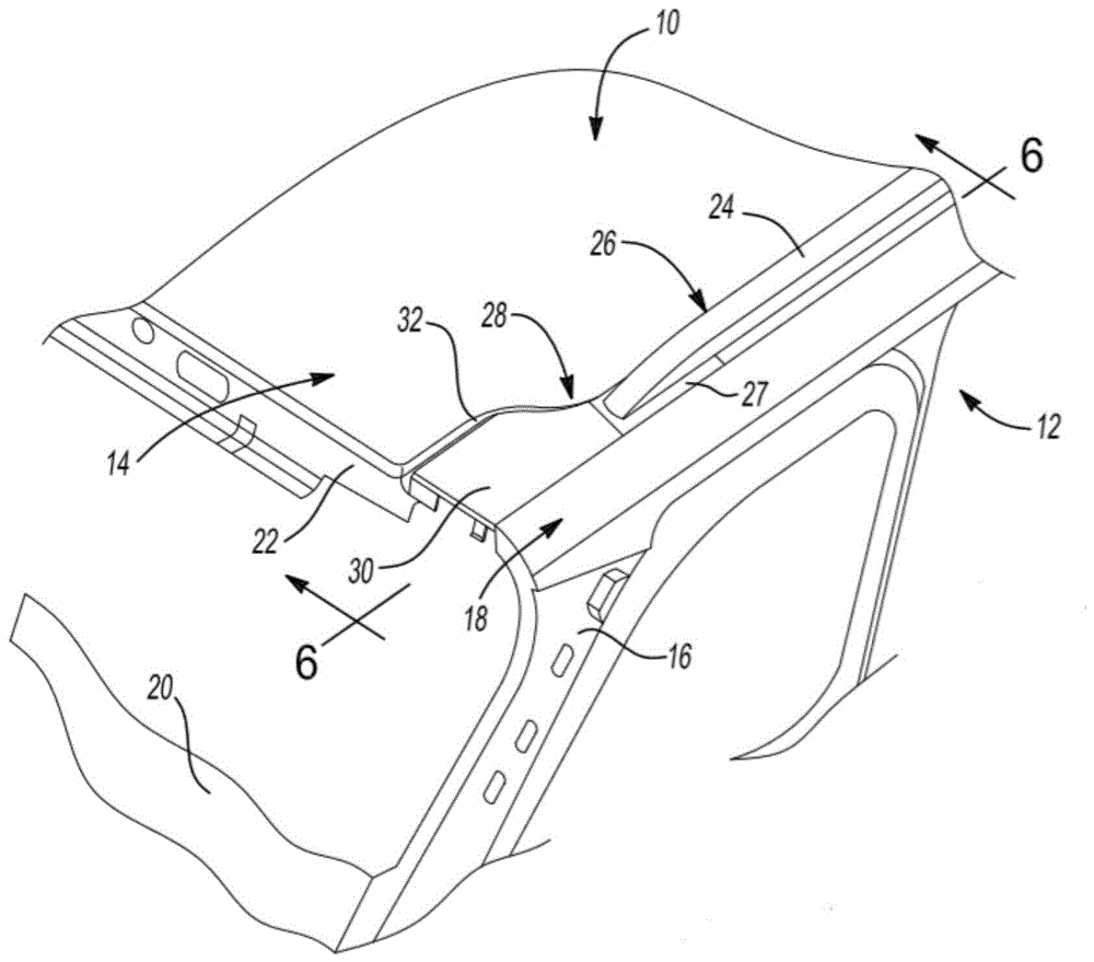
图1是根据示例性实施例的可拆卸式举升门铰链盖组件的向前看的右上方透视图;FIG. 1 is a forward looking upper right perspective view of a removable liftgate hinge cover assembly in accordance with an exemplary embodiment;
图2是图1的可拆卸式举升门铰链盖组件的左下方透视图;Figure 2 is a lower left perspective view of the removable liftgate hinge cover assembly of Figure 1;
图3是图1的可拆卸式举升门铰链盖组件的左下方透视图;Figure 3 is a lower left perspective view of the removable liftgate hinge cover assembly of Figure 1;
图4是图1的可拆卸式举升门铰链盖组件的板组件的分解组装图;Figure 4 is an exploded assembly view of the plate assembly of the detachable liftgate hinge cover assembly of Figure 1;
图5是与图1相似的右上方透视图,其中为了清楚起见移除了板组件;Figure 5 is a top right perspective view similar to Figure 1 with the plate assembly removed for clarity;
图6是在图1的截面6处截取的横截面端视图;以及FIG. 6 is a cross-sectional end view taken at
图7是图6的区域7的横截面端视图。FIG. 7 is a cross-sectional end view of region 7 of FIG. 6 .
具体实施方式Detailed ways
以下描述在本质上仅仅是示例性的,而并非旨在限制本公开、应用或使用。The following description is merely exemplary in nature and is not intended to limit the disclosure, application, or uses.
参看图1,机动车辆10包括车身12,车身12具有车顶14,车顶14连接到车身结构件(例如一个或多个车身支柱16)以在结构上支撑一个或多个车门(未示出)。车身面板18可用于在结构上将车顶14连接到车身支柱16。后举升门20(仅部分地示出)可旋转地连接到车顶14的结构构件22。车顶行李架组件24(示出右侧部分,而未示出左侧部分)连接到车顶14并且部分地定位在形成于车顶14与车身面板18之间的细长凹部26内。装饰构件27设置成覆盖细长凹部26的一部分,并且连接到并限定车顶行李架组件24的端部。Referring to FIG. 1, a
本公开的可拆卸式举升门铰链盖组件28在位于车顶14后方的两个位置(左侧和右侧)用作镜像组件,使第一部分定位在车顶行李架组件24与后举升门20之间并且使第二部分定位在车顶行李架组件与装饰构件27之间。以下对右侧组件的论述同样适用于左侧组件(未示出),因此本文中将不对其进行进一步论述。可拆卸式举升门铰链盖组件28的板组件30限定了定位在车顶行李架组件24与后举升门20之间的第一部分,并且板组件30部分地定位在扩展宽度后凹槽部分32内,扩展宽度后凹槽部分32限定位于细长凹部26后方的车顶铰链套,并在所示的安装位置覆盖铰链结构(未示出),该铰链结构将后举升门20可旋转地连接到车顶14的结构构件22。可拆卸式举升门铰链盖组件28的第二部分连接到车顶14并且还连接到车顶行李架组件24的装饰构件27,其将参考图6和7更详细地描述。为了便于维修与后举升门20相关联的部件并且在必要时完全移除后举升门20,可释放地连接可拆卸式举升门铰链盖组件28的板组件30。The removable liftgate
参看图2并且再次参看图1,板组件30利用耦接部分34可释放地耦接到支架33。当将支架33连接到板组件30时,耦接部分34通常防止在释放方向36上直接释放板组件30。为了将板组件30组装到支架33,板组件30可围绕旋转轴线38旋转,其将参考图7更详细地描述。Referring to FIG. 2 and referring again to FIG. 1 ,
参看图3并且再次参看图1和2,板组件30包括用于协助将板组件30连接并密封到车身12的车顶14的多个特征件。这些特征件包括固定到板组件30的聚合材料面板44的第一外边缘42的第一唇形密封件40,以及固定到面板44的第二外边缘48的第二唇形密封件46,第一外边缘42相对于第二外边缘48反向定位。第一抗振泡沫垫50和第二抗振泡沫垫52各自固定,例如使用粘合剂固定到面板44的平坦面54。Referring to FIG. 3 and referring again to FIGS. 1 and 2 , the
例如在模制面板44时,可弹性偏转的第一跨车定位器56和第二跨车定位器58一体地连接到面板44。第一跨车定位器56包括第一钩构件60,并且第二跨车定位器58包括第二钩构件62,其中第一钩构件60和第二钩构件62相对于彼此相对面向。如图1所示,跨车第一钩构件60和第二钩构件62弹性地偏转以摩擦地接触车顶14的后凹槽部分32的相对壁,并且各自偏转以在相对方向64、66上提供侧到侧对齐,从而提供板组件30的位置保持。一体地连接到面板44的模制夹68包括第三钩构件70,其定向成垂直于第一钩构件60和第二钩构件62两者的定向。当后举升门20处于关闭位置时,模制夹68将板组件30可释放地附接到凹槽隐藏件(未示出),该凹槽隐藏件设置在后举升门20上。The resiliently deflectable
板组件30进一步包括用于将板组件30摩擦地连接到车顶14的母夹组件72。母夹组件72一体地连接到凸起平台74,凸起平台74也一体地连接到面板44。母夹组件72包括第一最小偏转爪76和第二最大偏转爪78,其以彼此相对面向关系定位,从而在其之间形成接收槽80。在使用中,第一最小偏转爪76的偏转小于第二最大偏转爪78的偏转。连接到车顶14的公构件(参考图5所示和描述)进入接收槽80并且由第一偏转爪76和第二偏转爪78摩擦地夹持,以利用相反偏转的第一偏转爪76和第二偏转爪78的偏置力将板组件30可释放地保持到车顶14。公夹82(诸如W形夹)被摩擦地接合在面板44的凸起甲板部分84中。公夹82进入孔口(参考图5示出),该孔口形成在后凹槽部分32内的车顶14上,以提供面板44到车顶14的额外可释放摩擦接合。The
参看图4并且再次参看图1到3,以分解透视图示出了板组件30的各种部件,其包括第一唇形密封件40和第二唇形密封件46,其均可由弹性聚合材料提供,其可使用粘合剂固定到面板44。第一抗振泡沫垫50和第二抗振泡沫垫52均由弹性聚合泡沫材料制成,以允许具有比第一唇形密封件40和第二唇形密封件46的压缩性更大的压缩性。第一抗振泡沫垫50和第二抗振泡沫垫52两者均定位在第一唇形密封件40与第二唇形密封件46之间,并且如先前提到,其使用例如粘合剂固定到面板44的平坦面54。公夹82(诸如W形夹)使用在凸起甲板部分84上形成的钥匙孔形槽86摩擦地接合在面板44的凸起甲板部分84中。Referring to Figure 4 and again to Figures 1 through 3, various components of the
根据若干方面,第二夹子88可以用于代替母夹组件72,并且以相同方式安装。第一植绒条带90和第二植绒条带92也可添加到第一钩构件60和第二钩构件62,以协助保持第一钩构件60和第二钩构件62并且用于降低噪声和振动。保持构件94在与凸起甲板部分84的位置相对的端部处一体地连接到面板44。保持构件94用于将板组件30可释放地连接到支架33,其将参考图7更详细地描述。According to several aspects, the
参看图5并且再次参看图1到4,在安装板组件30之前,可以看到从细长凹部26向外延伸的后凹槽部分32,其中支架33的耦接部分34的一部分可见。后凹槽部分32提供协助连接并密封本公开的可拆卸式举升门铰链盖组件28的若干特征件。在平板区段100上设置了孔口96、98,其接纳用于安装后举升门20的铰链的紧固件(未示出)。后凹槽部分32的第一弯曲壁102为第一唇形密封件40提供密封表面,并且相对面向的第二弯曲壁104为第二唇形密封件46提供密封表面。凹槽部分32内从车顶14向上延伸的凸起公构件106进入参考图3所描述的母夹组件72的接收槽80,并且由第一偏转爪76和第二偏转爪78摩擦地夹持。细长孔口108接纳公夹82以提供面板44到车顶14的额外可释放摩擦接合。Referring to Figure 5 and again to Figures 1-4, prior to mounting the
参看图6并且再次参看图1到5,使用插入孔口112的一个或多个紧固件110,可拆卸式举升门铰链盖组件28的支架33的附接构件114可固定至位于细长凹部26内并且在车顶行李架组件24的装饰构件27下方的车顶14,其中孔口112设置在附接构件114上。支架33的附接构件114可进一步例如使用一个或多个紧固件连接到装饰构件27。示出了在使用耦接部分34安装之后的板组件30,其参考图7进行了更详细地描述。6 and again with reference to FIGS. 1-5, using one or
参看图7并且再次参看图1到6,支架33包括附接构件114,附接构件114具有一体地连接在一端处的耦接部分34。耦接部分34包括空腔116,其中第一接触构件118和第二接触构件120位于空腔116内。板组件30如下可释放地连接到耦接部分34。在首先相对于旋转轴线38在旋转方向122上旋转板组件30之后,保持构件94的钩形端部124被插入间隙开口126,该间隙开口126位于第一接触构件118与第二接触构件120之间。接着在与旋转方向122相反的旋转方向128上旋转板组件30,直到在板组件30的安装位置上,保持构件94直接接触第二接触构件120,并且钩形端部124的内部面130直接邻接第一接触构件118的第一面132。第一面132基本上垂直于第二接触构件120的第二面134定向,第二面134还在所示的板组件30的保持或安装位置直接邻接保持构件94的笔直部分138的平坦边缘136。根据若干方面,保持构件94的钩形端部124基本上垂直于笔直部分138定向,然而,钩形端部124可相对于笔直部分138以任何角度定向,该笔直部分138在安装位置提供保持能力。保持构件94与第一面132和第二面134中的每一者的邻接接触防止板组件30在释放方向36上释放。Referring to Figure 7 and again to Figures 1 to 6, the
当在旋转方向128上旋转板组件30时,第一抗振泡沫垫50和第二抗振泡沫垫52直接接触位于平板区段100上的铰链支架(未示出),并且随后弹性地压紧,并且第一跨车定位器56和第二跨车定位器58摩擦地接触第一弯曲壁102和第二弯曲壁104。继续在旋转方向128上旋转板组件30,公夹82进入并接合在孔口108内,并且凸起公构件106被接纳在母夹组件72的接收槽80中以保持板组件30的闭合位置,并且第一唇形密封件40和第二唇形密封件46摩擦地接触第一弯曲壁102和第二弯曲壁104。随后利用第一唇形密封件40和第二唇形密封件46与第一弯曲壁102和第二弯曲壁104的摩擦接触形成的密封使进入到板组件30下方的灰尘和湿气减到最少,同时允许在与释放方向36大体平行的从前向后的流动路径中排放。When the
为了释放板组件30,在旋转方向122上旋转板组件30,从而释放公夹82的接合,从母夹组件72的接收槽80内释放向上延伸的凸起公构件106的接合,并且释放第一跨车定位器56和第二跨车定位器58所提供的摩擦接触。然后,板组件30的进一步旋转允许保持构件94的钩形端部124通过间隙开口126与上述安装路径相反地向外往回移位。To release the
本公开的可拆卸式举升门铰链盖组件28提供了若干优点。这些优点包括与车顶纵梁和行李架系统一起制造并运输举升门盖组件的能力,同时还提供旋转铰链盖组件以进行拆卸和更换的能力。这准许在不需要移除车顶纵梁组件的情况下接达举升门铰链螺栓以进行检修。The removable liftgate
本公开的描述在本质上仅仅是示例性的,并且不背离本公开的主旨的变型旨在本公开的范围内。此类变型不应视为背离本公开的精神和范围。The description of the present disclosure is merely exemplary in nature, and modifications that do not depart from the gist of the present disclosure are intended to be within the scope of the present disclosure. Such variations should not be considered a departure from the spirit and scope of the present disclosure.
Claims (18)
Applications Claiming Priority (2)
| Application Number | Priority Date | Filing Date | Title |
|---|---|---|---|
| US15/661,483 | 2017-07-27 | ||
| US15/661,483 US10358852B2 (en) | 2017-07-27 | 2017-07-27 | Detachable lift gate hinge cover assembled to roof rail |
Publications (2)
| Publication Number | Publication Date |
|---|---|
| CN109306830A CN109306830A (en) | 2019-02-05 |
| CN109306830B true CN109306830B (en) | 2020-09-11 |
Family
ID=62196420
Family Applications (1)
| Application Number | Title | Priority Date | Filing Date |
|---|---|---|---|
| CN201810679481.1A Expired - Fee Related CN109306830B (en) | 2017-07-27 | 2018-06-27 | Detachable lifting door hinge cover assembled to roof rail |
Country Status (3)
| Country | Link |
|---|---|
| US (1) | US10358852B2 (en) |
| EP (1) | EP3434527B1 (en) |
| CN (1) | CN109306830B (en) |
Families Citing this family (6)
| Publication number | Priority date | Publication date | Assignee | Title |
|---|---|---|---|---|
| US10800351B2 (en) * | 2019-03-01 | 2020-10-13 | Toyota Motor Engineering & Manufacturing North America, Inc. | Roof ditch sealing assemblies for vehicles and methods for sealing roof ditches |
| JP7207075B2 (en) * | 2019-03-27 | 2023-01-18 | いすゞ自動車株式会社 | Hinge device and vehicle |
| US11028626B2 (en) | 2019-07-08 | 2021-06-08 | Ford Global Technologies, Llc | Roof hinge cover attachment strategies |
| US11920391B2 (en) * | 2021-09-10 | 2024-03-05 | Dee Zee, Inc. | Hinge covers for exposed vehicle door hinges |
| CN114673419B (en) * | 2021-10-20 | 2023-10-24 | 极氪汽车(宁波杭州湾新区)有限公司 | Vehicle door hinge structure and vehicle |
| CN116812014A (en) * | 2022-03-21 | 2023-09-29 | 标致雪铁龙汽车股份有限公司 | Hinge cover plate for vehicle tail door hinge, vehicle body structure and vehicle |
Citations (5)
| Publication number | Priority date | Publication date | Assignee | Title |
|---|---|---|---|---|
| US6142551A (en) * | 1998-12-17 | 2000-11-07 | Delphi Technologies, Inc. | Vehicle liftgate power operating system |
| CN1590196A (en) * | 2003-09-02 | 2005-03-09 | 本田技研工业株式会社 | Rear part structure of vehicle |
| CN105813896A (en) * | 2013-10-17 | 2016-07-27 | 艾罗运动有限公司 | An apparatus for mounting an article to a vehicle, and an article for use therewith |
| CN205836481U (en) * | 2016-05-24 | 2016-12-28 | 上汽通用五菱汽车股份有限公司 | A kind of tail-gate parting structure |
| CN106882273A (en) * | 2015-12-16 | 2017-06-23 | 本田技研工业株式会社 | Tail-gate is constructed |
Family Cites Families (4)
| Publication number | Priority date | Publication date | Assignee | Title |
|---|---|---|---|---|
| US6769731B1 (en) | 2003-05-05 | 2004-08-03 | General Motors Corporation | Cargo cover having hinged rails |
| JP4495718B2 (en) * | 2006-12-25 | 2010-07-07 | 本田技研工業株式会社 | Rear structure of the vehicle |
| US8641118B2 (en) | 2012-03-07 | 2014-02-04 | Nissan North America, Inc. | Vehicle body structure |
| US8979181B2 (en) | 2012-10-29 | 2015-03-17 | Nissan North America, Inc. | Vehicle body structure |
-
2017
- 2017-07-27 US US15/661,483 patent/US10358852B2/en active Active
-
2018
- 2018-05-17 EP EP18172789.2A patent/EP3434527B1/en not_active Not-in-force
- 2018-06-27 CN CN201810679481.1A patent/CN109306830B/en not_active Expired - Fee Related
Patent Citations (5)
| Publication number | Priority date | Publication date | Assignee | Title |
|---|---|---|---|---|
| US6142551A (en) * | 1998-12-17 | 2000-11-07 | Delphi Technologies, Inc. | Vehicle liftgate power operating system |
| CN1590196A (en) * | 2003-09-02 | 2005-03-09 | 本田技研工业株式会社 | Rear part structure of vehicle |
| CN105813896A (en) * | 2013-10-17 | 2016-07-27 | 艾罗运动有限公司 | An apparatus for mounting an article to a vehicle, and an article for use therewith |
| CN106882273A (en) * | 2015-12-16 | 2017-06-23 | 本田技研工业株式会社 | Tail-gate is constructed |
| CN205836481U (en) * | 2016-05-24 | 2016-12-28 | 上汽通用五菱汽车股份有限公司 | A kind of tail-gate parting structure |
Also Published As
| Publication number | Publication date |
|---|---|
| CN109306830A (en) | 2019-02-05 |
| US20190032383A1 (en) | 2019-01-31 |
| EP3434527B1 (en) | 2020-10-14 |
| EP3434527A1 (en) | 2019-01-30 |
| US10358852B2 (en) | 2019-07-23 |
Similar Documents
| Publication | Publication Date | Title |
|---|---|---|
| CN109306830B (en) | Detachable lifting door hinge cover assembled to roof rail | |
| US20160079706A1 (en) | Serviceable fixing system for connectors | |
| US11034307B1 (en) | Low profile toolbox and headache rack mounting bracket | |
| US20240053174A1 (en) | Bracket assembly | |
| WO2011013195A1 (en) | Bumper mounting structure | |
| CN109720416B (en) | Vehicle roof connection device | |
| KR20090074896A (en) | Car interior parts fixing clip | |
| JP2004066960A (en) | Mall clip | |
| US9434310B2 (en) | Attachment system for an exterior cover of a vehicle mirror assembly | |
| CN103935406B (en) | Automobile ventilation cover plate structure | |
| US9358935B2 (en) | Roof drip molding attachment | |
| JP2009506943A (en) | Inner cladding of a car door with cable harness | |
| CN104822953B (en) | Mounting structure utilizing locators and clips | |
| US11077889B2 (en) | Tailgate hinge clip | |
| US20080289154A1 (en) | Device and Method for Fixing a Trim Component on a Motor Vehicle Recess Post | |
| JP6392682B2 (en) | Curtain rail for vehicle | |
| JPH065266Y2 (en) | Mounting structure for vehicle console box | |
| CN101405919A (en) | Connector assembly with gasket | |
| CN112172482B (en) | Tail door switch bracket connecting structure | |
| CN114514146B (en) | vehicle decorative panels | |
| JP6917351B2 (en) | Clip mounting structure, clip mounting seat and clip mounting method | |
| JPH0522419Y2 (en) | ||
| JP2010269748A (en) | Mounting structure for weather strip | |
| JP2021172260A (en) | Pillar garnish | |
| WO2023181618A1 (en) | Clip installation structure |
Legal Events
| Date | Code | Title | Description |
|---|---|---|---|
| PB01 | Publication | ||
| PB01 | Publication | ||
| SE01 | Entry into force of request for substantive examination | ||
| SE01 | Entry into force of request for substantive examination | ||
| GR01 | Patent grant | ||
| GR01 | Patent grant | ||
| CF01 | Termination of patent right due to non-payment of annual fee |
Granted publication date: 20200911 |
|
| CF01 | Termination of patent right due to non-payment of annual fee |