CN109347301B - A self-powered method and device - Google Patents
A self-powered method and device Download PDFInfo
- Publication number
- CN109347301B CN109347301B CN201811314089.3A CN201811314089A CN109347301B CN 109347301 B CN109347301 B CN 109347301B CN 201811314089 A CN201811314089 A CN 201811314089A CN 109347301 B CN109347301 B CN 109347301B
- Authority
- CN
- China
- Prior art keywords
- mode
- power generation
- detection
- processing device
- self
- Prior art date
- Legal status (The legal status is an assumption and is not a legal conclusion. Google has not performed a legal analysis and makes no representation as to the accuracy of the status listed.)
- Active
Links
Images


Classifications
-
- H—ELECTRICITY
- H02—GENERATION; CONVERSION OR DISTRIBUTION OF ELECTRIC POWER
- H02K—DYNAMO-ELECTRIC MACHINES
- H02K35/00—Generators with reciprocating, oscillating or vibrating coil system, magnet, armature or other part of the magnetic circuit
- H02K35/02—Generators with reciprocating, oscillating or vibrating coil system, magnet, armature or other part of the magnetic circuit with moving magnets and stationary coil systems
-
- G—PHYSICS
- G01—MEASURING; TESTING
- G01R—MEASURING ELECTRIC VARIABLES; MEASURING MAGNETIC VARIABLES
- G01R31/00—Arrangements for testing electric properties; Arrangements for locating electric faults; Arrangements for electrical testing characterised by what is being tested not provided for elsewhere
-
- H—ELECTRICITY
- H02—GENERATION; CONVERSION OR DISTRIBUTION OF ELECTRIC POWER
- H02J—ELECTRIC POWER NETWORKS; CIRCUIT ARRANGEMENTS OR SYSTEMS FOR SUPPLYING OR DISTRIBUTING ELECTRIC POWER; SYSTEMS FOR STORING ELECTRIC ENERGY
- H02J7/00—Circuit arrangements for charging or discharging batteries or for supplying loads from batteries
- H02J7/32—Circuit arrangements for charging or discharging batteries or for supplying loads from batteries for charging batteries from a charging set comprising a non-electric prime mover rotating at constant speed
-
- H—ELECTRICITY
- H02—GENERATION; CONVERSION OR DISTRIBUTION OF ELECTRIC POWER
- H02K—DYNAMO-ELECTRIC MACHINES
- H02K7/00—Arrangements for handling mechanical energy structurally associated with dynamo-electric machines, e.g. structural association with mechanical driving motors or auxiliary dynamo-electric machines
- H02K7/18—Structural association of electric generators with mechanical driving motors, e.g. with turbines
- H02K7/1807—Rotary generators
- H02K7/1853—Rotary generators driven by intermittent forces
-
- H—ELECTRICITY
- H02—GENERATION; CONVERSION OR DISTRIBUTION OF ELECTRIC POWER
- H02N—ELECTRIC MACHINES NOT OTHERWISE PROVIDED FOR
- H02N2/00—Electric machines in general using piezoelectric effect, electrostriction or magnetostriction
- H02N2/18—Electric machines in general using piezoelectric effect, electrostriction or magnetostriction producing electrical output from mechanical input, e.g. generators
Landscapes
- Engineering & Computer Science (AREA)
- Power Engineering (AREA)
- Physics & Mathematics (AREA)
- General Physics & Mathematics (AREA)
- General Electrical Machinery Utilizing Piezoelectricity, Electrostriction Or Magnetostriction (AREA)
- Charge And Discharge Circuits For Batteries Or The Like (AREA)
Abstract
Description
技术领域technical field
本发明涉及自发电技术领域,特别是涉及一种自供电方法和装置。The present invention relates to the technical field of self-power generation, in particular to a self-power supply method and device.
背景技术Background technique
发电装置特别是动能发电装置是将动作的机械能转换为电能的装置,应用此类发电装置产生的电能来驱动处理装置来实现功能,系统本身是不需要其他能源输入,发电装置是系统的唯一电能来源。The power generation device, especially the kinetic energy power generation device, is a device that converts the mechanical energy of the action into electrical energy. The electrical energy generated by such a power generation device is used to drive the processing device to realize the function. The system itself does not need other energy input, and the power generation device is the only electrical energy in the system. source.
目前此类发电装置多为磁电式这就存在体积和电能的相互制约,体积小的发电装置单次动作的电能一般比较小,对于一些耗电量比较高的系统单次动作产生的电能时不足以完成预定任务的,这就需要将多次动作的电能合并使用,同时将多次间隙性电能转换为连续的电能输出,不至于系统在进行相关任务时供电中断。因此存在对于多次间歇性电能输入的控制和利用需求。At present, most of these power generation devices are of the magnetoelectric type, so there is a mutual restriction between the volume and the electric energy. The electric energy generated by a single action of a small power generation device is generally relatively small. If it is not enough to complete the predetermined task, it is necessary to combine the power of multiple actions, and at the same time, convert the intermittent power for multiple times into continuous power output, so that the power supply of the system will not be interrupted when the system is performing related tasks. There is therefore a need for control and utilization of multiple intermittent electrical energy inputs.
鉴于此,克服该现有技术所存在的缺陷是本技术领域亟待解决的问题。In view of this, overcoming the defects of the prior art is an urgent problem to be solved in the technical field.
发明内容SUMMARY OF THE INVENTION
本发明实施例要解决的技术问题是现有技术中自发电的控制模式单一,并没有充分发挥各场景下、各芯片器件组合的差异化供电可能。在自发电这一特殊的供电体系下,缺少一种行之有效的方式,克服现有技术中一些自发电场景下的工作稳定性问题和如何提高工作性能问题。The technical problem to be solved by the embodiments of the present invention is that the control mode of self-power generation in the prior art is single, and the differentiated power supply possibility of each chip device combination in each scenario is not fully utilized. Under the special power supply system of self-power generation, there is a lack of an effective way to overcome the problems of work stability and how to improve work performance in some self-power generation scenarios in the prior art.
本发明实施例进一步要解决的技术问题是如何对现有技术中工作模式进行深度分析,并通过预先设定好的工作模式切换方式,降低现有技术中无切换模式下可能造成的不满足要求的信号的发送,即浪费了电能又降低了通讯效率。The further technical problem to be solved by the embodiments of the present invention is how to conduct an in-depth analysis of the working mode in the prior art, and reduce the unsatisfactory requirements that may be caused by the non-switching mode in the prior art through the preset working mode switching mode. The transmission of the signal is a waste of electric energy and reduces the communication efficiency.
本发明实施例采用如下技术方案:The embodiment of the present invention adopts the following technical solutions:
第一方面,本发明提供了一种自供电装置,包括发电装置、整流装置、储能装置、检测装置和处理装置,其中,发电装置、整流装置、储能装置和处理装置依次电连,具体的:In a first aspect, the present invention provides a self-power supply device, comprising a power generation device, a rectifier device, an energy storage device, a detection device and a processing device, wherein the power generation device, the rectifier device, the energy storage device and the processing device are electrically connected in sequence, specifically of:
发电装置在至少两次外力动作下产生的间歇性电能,经整流装置整流后存储在储能装置中,其中储能装置中的一部电能流入处理装置,用于维持处理装置工作在模式1中;The intermittent electric energy generated by the power generation device under at least two external force actions is rectified by the rectifier device and stored in the energy storage device. A part of the electric energy in the energy storage device flows into the processing device to maintain the processing device in
检测装置的一端与发电装置相连,另一端连接处理装置的控制端口,用于提供可供处理装置使用的检测信号;其中,在所述检测装置检测结果满足预定的检测逻辑后,触发处理装置切换至工作模式2。One end of the detection device is connected to the power generating device, and the other end is connected to the control port of the processing device, which is used to provide a detection signal that can be used by the processing device; wherein, after the detection result of the detection device satisfies the predetermined detection logic, the switching of the processing device is triggered to work
优选的,触发所述间歇性电能的两次外力动作,具体包括:Preferably, triggering two external force actions of the intermittent electrical energy specifically includes:
发电装置在两次外力动作之间的间隔时间段满足以下条件:在后执行的外力动作被触发时,所述发电装置的输出端的电位差小于预设阈值。The interval time period between two external force actions of the power generating device satisfies the following condition: when the subsequent external force action is triggered, the potential difference of the output end of the power generating device is less than a preset threshold.
优选的,自供电装置在工作模式1的耗能比自供电装置在工作模式2的耗能低,其中,工作模式1用于实现自供电装置的启动功能,工作模式2是用于实现自供电装置主体功能。Preferably, the energy consumption of the self-powered device in working
优选的,包括:Preferred include:
在所述检测装置的一端是与发电装置相连时,所述检测逻辑具体为检测到发电装置完成指定次数能量的输出;和/或,When one end of the detection device is connected to the power generation device, the detection logic specifically detects that the power generation device has completed the output of energy for a specified number of times; and/or,
在所述检测装置的一端是与发电装置相连时,所述检测逻辑具体为根据发电装置产生电流的极性来切换处理装置的工作模式;和/或,When one end of the detection device is connected to the power generating device, the detection logic specifically switches the working mode of the processing device according to the polarity of the current generated by the power generating device; and/or,
在所述检测装置的一端是与储能装置相连时,所述检测逻辑具体为根据储能装置的能量聚集是否达到预设切换电能值,来确定切换处理装置的工作模式。When one end of the detection device is connected to the energy storage device, the detection logic specifically determines the operation mode of the switching processing device according to whether the energy accumulation of the energy storage device reaches a preset switching electric energy value.
优选的,在所述检测逻辑具体为检测到发电装置完成指定次数能量的输出时,所述检测装置具体由二极管构成的单向导通电路;Preferably, when the detection logic is specifically detected that the power generating device has completed the output of energy for a specified number of times, the detection device is specifically a unidirectional conduction circuit formed by a diode;
其中,在所述发电装置的输出端口具有第一极性和第二极性交替的特性,所述单向导通电路的输入端连接所述发电装置的第一输出端口和/或第二输出端口相连,用于选通所述第一极性或者第二极性构成检测信号;以便处理装置控制端口获取相应选通后的检测信号完成次数统计。Wherein, the output port of the power generating device has the characteristic of alternating first polarity and second polarity, and the input end of the unidirectional conduction circuit is connected to the first output port and/or the second output port of the power generating device are connected to each other, and are used for gating the first polarity or the second polarity to form a detection signal; so that the control port of the processing device obtains the statistics of the completion times of the detection signal after the corresponding gating.
优选的,所述单向导通电路具体包括:Preferably, the unidirectional conduction circuit specifically includes:
由二极管D5作为输入信号整流器,其中,二极管D5的正极作为检测装置的输入端,与发电装置的一个或者两个输出端口相连;The diode D5 is used as the input signal rectifier, wherein the anode of the diode D5 is used as the input end of the detection device, and is connected to one or two output ports of the power generating device;
所述二极管D5的负极与电阻R2的一端相连,其中,电阻R2的另一端与电阻R4的一端相连后,作为所述检测装置的输出端与所述处理装置的控制端口连接;所述电阻R4的另一端接地,并与所述电阻R2构成分压单元;The cathode of the diode D5 is connected to one end of the resistor R2, wherein after the other end of the resistor R2 is connected to one end of the resistor R4, it is connected to the control port of the processing device as the output end of the detection device; the resistor R4 The other end is grounded, and forms a voltage divider unit with the resistor R2;
其中,所述二极管D5和电阻R2之间还并联一电容C3,所述电容C3的另一端接地,构成高频滤波支路。A capacitor C3 is connected in parallel between the diode D5 and the resistor R2, and the other end of the capacitor C3 is grounded to form a high-frequency filter branch.
优选的,检测逻辑具体为根据发电装置产生电流的极性来切换处理装置的工作模式时,所述检测装置具体由二极管构成的正极单向导通电路;Preferably, when the detection logic is specifically to switch the working mode of the processing device according to the polarity of the current generated by the power generating device, the detection device is specifically a positive unidirectional conduction circuit formed by a diode;
其中,在所述发电装置输出端口对应处理装置的模式1时,发电装置的第一输出端口输出负电压,所述发电装置输出端口对应模式2时,发电装置的第一输出端口输出正电压,所述正极单向导通电路的输入端连接所述发电装置的第一输出端口相连,用于阻隔所述负电压,选通所述正电压。Wherein, when the output port of the power generating device corresponds to
优选的,在所述二极管构成的正极单向导通电路具体为:Preferably, the anode unidirectional conduction circuit formed by the diode is specifically:
由二极管D5作为输入信号整流器,其中,二极管D5的正极作为检测装置的输入端,与发电装置的第一输出端口相连;并且,所述发电装置的第一输出端口对应模式1输出负电压,所述输出端口对应模式2输出正电压;The diode D5 is used as the input signal rectifier, wherein the anode of the diode D5 is used as the input end of the detection device and is connected to the first output port of the power generating device; and the first output port of the power generating device corresponds to the
所述二极管D5的负极与电阻R2的一端相连,其中,电阻R2的另一端与电阻R4的一端相连后,作为所述检测装置的输出端与所述处理装置的控制端口连接;所述电阻R4的另一端接地,并与所述电阻R2构成分压单元;The cathode of the diode D5 is connected to one end of the resistor R2, wherein after the other end of the resistor R2 is connected to one end of the resistor R4, it is connected to the control port of the processing device as the output end of the detection device; the resistor R4 The other end is grounded, and forms a voltage divider unit with the resistor R2;
其中,所述二极管D5和电阻R2之间还并联一电容C3,所述电容C3的另一端接地,构成高频滤波支路。A capacitor C3 is connected in parallel between the diode D5 and the resistor R2, and the other end of the capacitor C3 is grounded to form a high-frequency filter branch.
优选的,在所述检测逻辑具体为根据发电装置产生电流的极性来切换处理装置的工作模式时,所述检测装置包括两套采集组件,其中第一套采集组件具体包括:Preferably, when the detection logic specifically switches the working mode of the processing device according to the polarity of the current generated by the power generating device, the detection device includes two sets of acquisition components, wherein the first set of acquisition components specifically includes:
由二极管D5作为输入信号整流器,其中,二极管D5的正极作为检测装置的第一输入端,与发电装置的第一输出端口相连;The diode D5 is used as the input signal rectifier, wherein the anode of the diode D5 is used as the first input end of the detection device and is connected to the first output port of the power generating device;
所述二极管D5的负极与电阻R2的一端相连,其中,电阻R2的另一端与电阻R4的一端相连后,作为所述检测装置的输出端与所述处理装置的第一控制端口连接;所述电阻R4的另一端接地,并与所述电阻R2构成分压单元;The cathode of the diode D5 is connected to one end of the resistor R2, wherein after the other end of the resistor R2 is connected to one end of the resistor R4, it is connected to the first control port of the processing device as the output end of the detection device; the The other end of the resistor R4 is grounded, and forms a voltage dividing unit with the resistor R2;
第二套采集组件具体包括:The second set of collection components specifically includes:
由二极管D4作为输入信号整流器,其中,二极管D4的正极作为检测装置的第二输入端,与发电装置的第二输出端口相连;The diode D4 is used as the input signal rectifier, wherein the anode of the diode D4 is used as the second input end of the detection device, and is connected to the second output port of the power generating device;
所述二极管D4的负极与电阻R1的一端相连,其中,电阻R1的另一端与电阻R3的一端相连后,作为所述检测装置的输出端与所述处理装置的第二控制端口连接;所述电阻R3的另一端接地,并与所述电阻R1构成分压单元。The cathode of the diode D4 is connected to one end of the resistor R1, wherein after the other end of the resistor R1 is connected to one end of the resistor R3, it is connected to the second control port of the processing device as the output end of the detection device; the The other end of the resistor R3 is grounded, and forms a voltage dividing unit with the resistor R1.
优选的,所述检测逻辑具体为根据储能装置的能量聚集是否达到预设切换电能值,来确定切换处理装置的工作模式时,所述检测装置具体为电压检测器,当储能模块的电压未达到预设值时,检测装置的输出关闭;当储能模块的电压达到预设值时,检测装置的输出打开;所述电压检测器包括以下几种型号中的任意一种:型号BL8506、型号LY61C。Preferably, the detection logic is specifically to determine the working mode of the switching processing device according to whether the energy accumulation of the energy storage device reaches a preset switching electric energy value, the detection device is specifically a voltage detector, when the voltage of the energy storage module is When the preset value is not reached, the output of the detection device is turned off; when the voltage of the energy storage module reaches the preset value, the output of the detection device is turned on; the voltage detector includes any one of the following models: model BL8506, Model LY61C.
优选的,所述整流装置由两组整流二极管构成,每一组整流二极管中包含至少两个二极管,其中二极管D1的正极接地,二极管D1的负极和二极管D2的正极相连,并且,二极管D1的负极还作为该组整流二极管的输入端与发电装置的一输出口相连,所述二极管D2的负极连接储能装置;具体的:Preferably, the rectifier device is composed of two groups of rectifier diodes, each group of rectifier diodes includes at least two diodes, wherein the anode of the diode D1 is grounded, the cathode of the diode D1 is connected to the anode of the diode D2, and the cathode of the diode D1 is connected to the ground. It is also connected to an output port of the power generating device as the input end of the group of rectifier diodes, and the negative electrode of the diode D2 is connected to the energy storage device; specifically:
第一组整流二极管的输入端作为所述整流装置的第一输入端,与所述发电装置的第一输出口相连,第二组整流二极管的输入端作为所述整流装置的第二输入端,与所述发电装置的第二输出口相连;The input end of the first group of rectifier diodes is used as the first input end of the rectifier device and is connected to the first output port of the power generating device, and the input end of the second group of rectifier diodes is used as the second input end of the rectifier device, connected with the second output port of the power generating device;
所述第一组整流二极管和所述第二组整流二极管的输出端均与所述储能装置相连。The output ends of the first group of rectifier diodes and the second group of rectifier diodes are both connected to the energy storage device.
优选的,所述储能装置包括:Preferably, the energy storage device includes:
电容、电感、储能化学材料和储能机械装置中的一种或者多种。One or more of capacitors, inductors, energy storage chemistries, and energy storage mechanisms.
优选的,在所述储能装置具体为电容C1时,所述电容的一端接地,电容的另一端与所述整流装置的输出端相连,并且电容的另一端还与所述处理装置的电源输入端口相连。Preferably, when the energy storage device is a capacitor C1, one end of the capacitor is grounded, the other end of the capacitor is connected to the output end of the rectifier device, and the other end of the capacitor is also connected to the power input of the processing device port is connected.
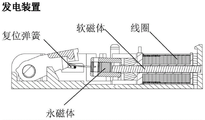
优选的,发电装置为磁电式脉冲发电装置,包含软磁体、永磁体及线圈;或者,所述发电装置为压电陶瓷。Preferably, the power generating device is a magnetoelectric pulse power generating device, comprising a soft magnet, a permanent magnet and a coil; or, the power generating device is a piezoelectric ceramic.
优选的,还包括传感器装置,所述传感器装置由发电装置在第一运动方向运动时产生的电能直接或间接供电。Preferably, a sensor device is also included, and the sensor device is directly or indirectly powered by the electric energy generated when the power generating device moves in the first movement direction.
优选的,传感器为微动开关、磁动开关、干簧管开关、轻触开关的一种或多种,传感器在发电装置在第一运动方向运动时,处于触发状态,用以识别按键的按下动作。Preferably, the sensor is one or more of a micro switch, a magnetic switch, a dry reed switch, and a tact switch, and the sensor is in a triggered state when the power generating device moves in the first movement direction, and is used to identify the pressing of the key. next action.
优选的,传感器为压力传感器。Preferably, the sensor is a pressure sensor.
第二方面,本发明还包括一种自供电方法,包括发电装置、整流装置、储能装置、检测装置和处理装置,其中,发电装置、整流装置、储能装置和处理装置依次电连,具体的:In the second aspect, the present invention also includes a self-power supply method, including a power generating device, a rectifying device, an energy storage device, a detection device and a processing device, wherein the power generating device, the rectifying device, the energy storage device and the processing device are electrically connected in sequence, specifically of:
所述检测装置的一端连接所述发电装置和/或储能装置,将检测结果传递给所述处理装置;One end of the detection device is connected to the power generation device and/or the energy storage device, and the detection result is transmitted to the processing device;
所述处理装置验证预定的检测逻辑;其中,若满足第一检测逻辑,则控制工作模式从模式1切换为模式2。The processing device verifies the predetermined detection logic; wherein, if the first detection logic is satisfied, the control working mode is switched from
优选的,包括:Preferred include:
所述第一检测逻辑具体为检测到发电装置完成指定次数能量的输出;和/或,The first detection logic is specifically to detect that the power generating device completes the output of energy for a specified number of times; and/or,
所述第一检测逻辑具体为根据发电装置产生电流的极性来切换处理装置的工作模式;和/或,The first detection logic is specifically to switch the working mode of the processing device according to the polarity of the current generated by the power generating device; and/or,
所述第一检测逻辑具体为根据储能装置的能量聚集是否达到预设切换电能值,来确定切换处理装置的工作模式。The first detection logic is specifically to determine the working mode of the switching processing device according to whether the energy accumulation of the energy storage device reaches a preset switching power value.
优选的,所述第一检测逻辑具体为根据发电装置产生电流的极性来切换处理装置的工作模式,所述检测装置具体由二极管构成的正极单向导通电路,方法包括:Preferably, the first detection logic is specifically to switch the working mode of the processing device according to the polarity of the current generated by the power generating device, and the detection device is specifically a positive unidirectional conduction circuit formed by a diode, and the method includes:
发电装置获取第一外力动作发电,与所述检测装置相连的电极输出负电压,则相应检测装置与处理装置相连的输出端口为低电平;所述处理装置在获得电能后进入默认的模式1工作状态;The power generation device obtains the first external force to act to generate electricity, and the electrode connected to the detection device outputs a negative voltage, then the output port connected to the corresponding detection device and the processing device is at a low level; the processing device enters the
发电装置获取第二外力动作发电,与所述检测装置相连的电极输出正电压,则相应检测装置与处理装置相连的输出端口为高电平;所述处理装置在获得所述高电平的检测信号后,将自身的工作模式由模式1切换为模式2。The power generating device obtains the second external force to act to generate electricity, and the electrode connected to the detection device outputs a positive voltage, then the output port connected to the corresponding detection device and the processing device is at a high level; the processing device obtains the high level detection After receiving the signal, switch its working mode from
优选的,在所述模式1为基础程序运行模式,所述模式2为无线发射模式,所述若满足第一检测逻辑,则发送触发指令给处理装置,以便处理装置从模式1切换为模式2,具体包括:Preferably, when the
在发电装置接收到第一次外部动作后,发出电量供所述处理装置处于基础程序运行模式,并等待由第二次外部动作所触发;After the power generating device receives the first external action, it sends out electricity for the processing device to be in the basic program running mode, and waits for being triggered by the second external action;
当第二次动作完成后,相应检测装置确定检测结果满足预定的检测逻辑,则触发所述处理装置,将工作模式从所述基础程序运行模式切换到无线发射模式。After the second action is completed, the corresponding detection device determines that the detection result satisfies the predetermined detection logic, and triggers the processing device to switch the working mode from the basic program running mode to the wireless transmission mode.
优选的,若满足第二检测逻辑,则发送触发指令给处理装置,以便处理装置从模式2切换为模式1。Preferably, if the second detection logic is satisfied, a trigger instruction is sent to the processing device, so that the processing device switches from
优选的,所述第二检测逻辑包括:Preferably, the second detection logic includes:
根据储能装置的能量聚集是否低于预设切换电能值,来确定切换处理装置的工作模式,由工作模式2切换为工作模式1;和/或,According to whether the energy accumulation of the energy storage device is lower than the preset switching electric energy value, the working mode of the switching processing device is determined, and the working
根据最近一次能量输出后,超出预设时间阈值未收到下一次的能量输出,确定切换处理装置的工作模式,由工作模式2切换为工作模式1。According to the fact that after the latest energy output, the next energy output is not received beyond the preset time threshold, the working mode of the switching processing device is determined, and the working
优选的,所述方法还包括:Preferably, the method further includes:
所述处理装置验证预定的检测逻辑;其中,若满足第三检测逻辑,则控制工作模式从模式2切换为模式3,或者控制工作模式从模式1切换为模式3。The processing device verifies the predetermined detection logic; wherein, if the third detection logic is satisfied, the control working mode is switched from the
与现有技术相比,本发明实施例的有益效果在于:本发明分析了现有自发电应用中,发电装置和外力动作驱动的间歇特性、发电极性特性和/或能量堆叠特性,并进一步在分析出处理装置的工作模式可以拆分为不同阶段,对应不同发电量的多种模式;通过设置检测装置,配合处理装置中预定的检测逻辑,实现了对于不同电能需求下的不同工作模式的精准切换。提高了自发电应用这一特殊场景下的用电效率和工作效率,克服了现有技术中存在处理器正常启动下的某种工作模式失败问题。Compared with the prior art, the beneficial effects of the embodiments of the present invention are: the present invention analyzes the intermittent characteristics, power generation polarity characteristics and/or energy stacking characteristics of the power generation device and external force action driving in the existing self-generation applications, and further It is analyzed that the working mode of the processing device can be divided into different stages, corresponding to various modes of different power generation; by setting the detection device and cooperating with the predetermined detection logic in the processing device, the different working modes under different power requirements are realized. Precise switching. The power consumption efficiency and work efficiency in the special scenario of self-generating application are improved, and the problem of failure in a certain working mode when the processor is normally started in the prior art is overcome.
附图说明Description of drawings
为了更清楚地说明本发明实施例或现有技术中的技术方案,下面将对实施例或现有技术描述中所需要使用的附图作简单地介绍,显而易见地,下面描述中的附图仅仅是本发明的一些实施例,对于本领域普通技术人员来讲,在不付出创造性劳动的前提下,还可以根据这些附图获得其它的附图。In order to explain the embodiments of the present invention or the technical solutions in the prior art more clearly, the following briefly introduces the accompanying drawings that need to be used in the description of the embodiments or the prior art. Obviously, the accompanying drawings in the following description are only These are some embodiments of the present invention, and for those of ordinary skill in the art, other drawings can also be obtained from these drawings without creative effort.
图1是本发明实施例提供的一种自发电装置和发电电势效果示意图;1 is a schematic diagram of a self-generating device and the effect of power generation potential provided by an embodiment of the present invention;
图2是本发明实施例提供的一种储能装置对应自发电装置电势的放能效果示意图;2 is a schematic diagram of an energy discharge effect of an energy storage device corresponding to the potential of a self-generating device provided by an embodiment of the present invention;
图3是本发明实施例提供的一种自供电装置的结构示意图;3 is a schematic structural diagram of a self-powered device provided by an embodiment of the present invention;
图4是本发明实施例提供的一种发电装置的结构示意图;4 is a schematic structural diagram of a power generation device provided by an embodiment of the present invention;
图5是本发明实施例提供的另一种发电装置的结构示意图;5 is a schematic structural diagram of another power generation device provided by an embodiment of the present invention;
图6是本发明实施例提供的一种依据发电次数触发模式切换的电势效果示意图;6 is a schematic diagram of the potential effect of triggering mode switching according to the number of power generation provided by an embodiment of the present invention;
图7是本发明实施例提供的一种发电装置管脚极性和外力动作示意图;7 is a schematic diagram of pin polarity and external force action of a power generation device provided by an embodiment of the present invention;
图8是本发明实施例提供的一种正负极电势的效果示意图;8 is a schematic diagram of the effect of a positive and negative electrode potential provided by an embodiment of the present invention;
图9是本发明实施例提供的一种压电陶瓷发电装置的工作状态示意图;9 is a schematic diagram of a working state of a piezoelectric ceramic power generating device provided by an embodiment of the present invention;
图10是本发明实施例提供的一种依据总电能大小触发模式切换的电势效果示意图;10 is a schematic diagram of the potential effect of triggering mode switching according to the magnitude of the total electric energy according to an embodiment of the present invention;
图11是本发明实施例提供的对应于方式一的一种自供电装置的结构示意图;11 is a schematic structural diagram of a self-powered device corresponding to
图12是本发明实施例提供的对应于方式二的一种自供电装置的结构示意图;12 is a schematic structural diagram of a self-powered device corresponding to
图13是本发明实施例提供的对应于方式二的另一种自供电装置的结构示意图;13 is a schematic structural diagram of another self-powered device corresponding to
图14是本发明实施例提供的对应于方式二的还一种检测装置的结构示意图;14 is a schematic structural diagram of still another detection device corresponding to
图15是本发明实施例提供的对应于方式三的一种自供电装置的结构示意图;15 is a schematic structural diagram of a self-powered device corresponding to
图16是本发明实施例提供的一种整流装置的结构示意图;16 is a schematic structural diagram of a rectifier device provided by an embodiment of the present invention;
图17是本发明实施例提供的一种自供电方法的流程示意图;17 is a schematic flowchart of a self-power supply method according to an embodiment of the present invention;
图18是本发明实施例提供的一种依据发电极性完成模式切换的自供电方法的流程示意图;18 is a schematic flowchart of a self-power supply method for completing mode switching according to the power generation polarity according to an embodiment of the present invention;
图19是本发明实施例提供的一种自供电装置的结构主视图;19 is a front view of the structure of a self-powered device provided by an embodiment of the present invention;
图20是本发明实施例提供的一种自发电多键无线开关的外部结构示意图;20 is a schematic diagram of the external structure of a self-generating multi-key wireless switch provided by an embodiment of the present invention;
图21是本发明实施例提供的一种自发电多键无线开关的内部结构示意图;21 is a schematic diagram of the internal structure of a self-generating multi-key wireless switch provided by an embodiment of the present invention;
图22是本发明实施例提供的一个未采用本发明解决方案时处理装置端获取电能效果示意图;FIG. 22 is a schematic diagram of the effect of obtaining electric energy by the processing device side when the solution of the present invention is not adopted according to an embodiment of the present invention;
图23是本发明实施例提供的一个采用本发明解决方案时处理装置端获取电能效果示意图。FIG. 23 is a schematic diagram of the effect of obtaining electric energy by the processing device end when the solution of the present invention is adopted according to an embodiment of the present invention.
具体实施方式Detailed ways
为了使本发明的目的、技术方案及优点更加清楚明白,以下结合附图及实施例,对本发明进行进一步详细说明。应当理解,此处所描述的具体实施例仅仅用以解释本发明,并不用于限定本发明。In order to make the objectives, technical solutions and advantages of the present invention clearer, the present invention will be further described in detail below with reference to the accompanying drawings and embodiments. It should be understood that the specific embodiments described herein are only used to explain the present invention, but not to limit the present invention.
在本发明的描述中,术语“内”、“外”、“纵向”、“横向”、“上”、“下”、“顶”、“底”等指示的方位或位置关系为基于附图所示的方位或位置关系,仅是为了便于描述本发明而不是要求本发明必须以特定的方位构造和操作,因此不应当理解为对本发明的限制。In the description of the present invention, the orientation or positional relationship indicated by the terms "inner", "outer", "longitudinal", "lateral", "upper", "lower", "top", "bottom", etc. are based on the drawings The orientation or positional relationship shown is only for the convenience of describing the present invention rather than requiring the present invention to be constructed and operated in a specific orientation, and therefore should not be construed as a limitation of the present invention.
如图1所示,系统中所描述的发电装置M1动作产生的电势如图1右边所示,发电装置动作一次产生一个如图1中B所示部分的能量,该能量的特点是持续时间短,峰值高。如图1中A所示,其动作产生的能量可能是正的也可能是负的。多次动作(需要强调这里的动作是广义上的动作,是指发能够让电装置产生能量的一切行为,可以是机械的也可以是非机械的,可以是操作部正向运动也可以是逆向运动等)。As shown in Figure 1, the electric potential generated by the action of the power generation device M1 described in the system is shown on the right side of Figure 1. The power generation device operates once to generate a part of energy as shown in B in Figure 1, which is characterized by a short duration. , the peak is high. As shown by A in Figure 1, the energy generated by its action may be positive or negative. Multiple actions (it needs to be emphasized that the action here is an action in a broad sense, which refers to all actions that can make an electrical device generate energy, which can be mechanical or non-mechanical, and can be a forward or reverse movement of the operating part. Wait).
T1为两次外力动作的时间间隙,正是由于单次动作产生的能量持续时间小于动作间隔T1,所以将多次能量的集合起来完成一次高耗能任务是本发明的主要内容。T1 is the time interval between two external force actions. It is precisely because the duration of energy generated by a single action is shorter than the action interval T1, so it is the main content of the present invention to collect multiple energy to complete a high energy-consuming task.
现有技术中,对单次尖峰能量的利用,采用先存储能量再释放的方式进行。储能装置的能量波形如图2所示T3持续的时间的长短取决于处理装置的情况。在T3周期内无法完成既定任务的系统因此将会在下次动作能量产生前中断,从而无法继续任务。本发明不仅考虑了上述中断问题,而是进一步考虑到现有技术中,即便在发电功能不足的情况下,也会强行的执行预设的功能,例如通信模块中的无线通讯动作,这样的结果不仅浪费了自发电的电能,也无法释放出有效的无线信号强度,以至于对端无法有效接收或者识别,造成了本身就极度稀缺的自发电的电能浪费。In the prior art, the utilization of a single peak energy is performed by first storing the energy and then releasing it. The energy waveform of the energy storage device, as shown in FIG. 2 , the duration of T3 depends on the condition of the processing device. A system that is unable to complete a given task within the T3 cycle will therefore be interrupted before the next action energy is generated, so that the task cannot be continued. The present invention not only considers the above-mentioned interruption problem, but also further considers that in the prior art, even when the power generation function is insufficient, the preset function, such as the wireless communication action in the communication module, will be forcibly executed. Not only the self-generated power is wasted, but also the effective wireless signal strength cannot be released, so that the peer end cannot effectively receive or identify, resulting in a waste of self-generated power that is extremely scarce.
此外,下面所描述的本发明各个实施方式中所涉及到的技术特征只要彼此之间未构成冲突就可以相互组合。In addition, the technical features involved in the various embodiments of the present invention described below can be combined with each other as long as they do not conflict with each other.
实施例1:Embodiment 1:
本发明实施例1提供了一种自供电装置,如图3所示,包括发电装置、整流装置、储能装置、检测装置和处理装置,其中,发电装置、整流装置、储能装置和处理装置依次电连,具体的:
发电装置在至少两次外力动作下产生的间歇性电能,经整流装置整流后存储在储能装置中,其中储能装置中的一部电能流入处理装置,用于维持处理装置工作在模式1中;The intermittent electric energy generated by the power generation device under at least two external force actions is rectified by the rectifier device and stored in the energy storage device. A part of the electric energy in the energy storage device flows into the processing device to maintain the processing device in
检测装置的一端与发电装置相连,另一端连接处理装置的控制端口,用于提供可供处理装置使用的检测信号;其中,在所述检测装置检测结果满足预定的检测逻辑后,触发处理装置切换至工作模式2。One end of the detection device is connected to the power generating device, and the other end is connected to the control port of the processing device, which is used to provide a detection signal that can be used by the processing device; wherein, after the detection result of the detection device satisfies the predetermined detection logic, the switching of the processing device is triggered to work
其中,自供电装置在工作模式1的耗能比自供电装置在工作模式2的耗能低,例如,工作模式1用于实现自供电装置的启动功能,以及相应基础低功耗的响应功能,工作模式2是用于实现自供电装置主体功能,在本发明实施例中通常指高功耗的功能。其中,工作模式1和工作模式2在本发明各实施例中也分别被简称为模式1和模式2。Among them, the energy consumption of the self-powered device in working
本发明实施例分析了现有自发电应用中,发电装置和外力动作驱动的间歇特性、发电极性特性和/或能量堆叠特性,并进一步在分析出处理装置的工作模式可以拆分为不同阶段,对应不同发电量的多种模式;通过设置检测装置,配合处理装置中预定的检测逻辑,实现了对于不同电能需求下的不同工作模式的精准切换。提高了自发电应用这一特殊场景下的用电效率和工作效率,克服了现有技术中存在处理器正常启动下的某种工作模式失败问题。The embodiment of the present invention analyzes the intermittent characteristics, power generation polarity characteristics and/or energy stacking characteristics of the power generation device and external force action drive in the existing self-generation application, and further analyzes that the working mode of the processing device can be divided into different stages , corresponding to various modes of different power generation; by setting the detection device and cooperating with the predetermined detection logic in the processing device, the precise switching of different working modes under different power requirements is realized. The power consumption efficiency and work efficiency in the special scenario of self-generating application are improved, and the problem of failure in a certain working mode when the processor is normally started in the prior art is overcome.
在本发明实施例中所述储能装置包括:电容、电感、储能化学材料和储能机械装置中的一种或者多种。为了描述上的简便,本发明后续实施例及其附图中,将主要以电容的形式来呈现储能装置,但是,这并非是对本发明方案中所使用的储能装置类型的限定。In the embodiment of the present invention, the energy storage device includes: one or more of capacitors, inductors, energy storage chemical materials, and energy storage mechanical devices. For simplicity of description, in the subsequent embodiments of the present invention and the accompanying drawings, the energy storage device is mainly presented in the form of capacitors, but this is not a limitation on the type of energy storage device used in the solution of the present invention.
结合本发明实施例,对于触发所述间歇性电能的两次外力动作,给与了一种目标状态的描述,具体包括:With reference to the embodiment of the present invention, a description of a target state is given for the two external force actions that trigger the intermittent electrical energy, which specifically includes:
发电装置在两次外力动作之间的间隔时间段满足以下条件:在后执行的外力动作被触发时,所述发电装置的输出端的电位差小于预设阈值。其中,所述设定预设阈值为10%-30%。所述电位差小于预设阈值是为了设计和实现的方案,在本发明实施例中优选的理想电位差是零,即刚好发电装置前一发电过程产生电能都转换给了储电装置,便进行下一轮的发电过程。此处的目标状态是为了达到外力动作和自发电过程的最优匹配为目标的,考虑到如果外力动作触发的发电时间间隔过短,就会造成上一轮的发电装置电能还没有效释放给储能装置,下一轮的外力动作就产生了;由于,附加给发电装置的外力动作通常是无法带来发电装置发电量上的累加的(也有例外,如转轮式的发电装置,如图4所示(其包含软磁体、永磁体和线圈组成的发电体和多个齿轮组成的传动装置),连续的外力动作可以提高转轮的转速,从而产生发电量大小累加的效果),尤其是针对拨片式的发电装置,如图5所示(其包含软磁体、永磁体和线圈组成的发电体和复位弹簧组成的复位装置),连续的短间隔的外力动作,只会增加相应发电装置持续发电的时间,这对于储电装置的储电过程来说,性价比没有本发明实施例上述目标状态的高。因此,上述提出的目标状态适用于例如拨片、弹片式的发电装置。The interval time period between two external force actions of the power generating device satisfies the following condition: when the subsequent external force action is triggered, the potential difference of the output end of the power generating device is less than a preset threshold. Wherein, the set preset threshold is 10%-30%. The potential difference less than the preset threshold is for the purpose of design and implementation. In the embodiment of the present invention, the preferred ideal potential difference is zero, that is, the electric energy generated in the previous power generation process of the power generation device is converted to the power storage device, and the process is carried out. The next round of power generation process. The target state here is to achieve the optimal match between the external force action and the self-generating process. Considering that if the power generation time interval triggered by the external force action is too short, it will cause the power of the previous round of power generation devices to be not effectively released to the power generation. Energy storage device, the next round of external force action is generated; because the external force action attached to the power generation device usually cannot bring about the accumulation of the power generation of the power generation device (there are exceptions, such as the wheel-type power generation device, as shown in the figure 4 (which includes a power generator composed of soft magnets, permanent magnets and coils, and a transmission composed of multiple gears), continuous external force action can increase the speed of the runner, resulting in the effect of accumulating power generation), especially For the paddle-type power generation device, as shown in Figure 5 (which includes a power generator composed of soft magnets, permanent magnets and coils, and a reset device composed of a reset spring), continuous short-interval external force action will only increase the corresponding power generation device. The time for continuous power generation, for the power storage process of the power storage device, the cost performance is not as high as that of the above-mentioned target state of the embodiment of the present invention. Therefore, the target state proposed above is applicable to, for example, a paddle, dome-type power generating device.
需要强调的是,本发明实施例1所提出的方案,对于上述拨片、弹片式的发电装置(在本发明实施例中也被成为复位式的发电装置),以及上述转轮式的发电装置均适用。It should be emphasized that the solution proposed in
基于本发明实施例1中所描述的检测装置的至少两种连接方式,以及在描述方案过程中引入的检测逻辑概念,在此,提供了至少三种方式对于上述连接方式与检测逻辑之间的实现方式给予具体的阐述,如下包括:Based on the at least two connection modes of the detection device described in
方式一、method one,
在所述检测装置的一端是与发电装置相连时,所述检测逻辑具体为检测到发电装置完成指定次数能量的输出。该方式适用于单次外力动作下,发电装置所产生的电能能够标定的场景。When one end of the detection device is connected to the power generation device, the detection logic specifically detects that the power generation device has completed the output of energy for a specified number of times. This method is suitable for scenarios where the electric energy generated by the power generating device can be calibrated under a single external force action.
如图6所示,是发电装置多次动作的波形,下部分是采用本发明所述控制方法后储能装置的能量波形。在图中,L1表示了发电装置在外力动作触发下发电时储能装置的能量变化轨迹,此时能量流向处理装置,处理装置开始工作,完成必要的准备工作,并开始监听检测装置的检测结果,此时处理装置工作在工作模式1(如图6中的L2段所示),在L2阶段储能装置的能量下降得非常慢,当下一次动作来临,储能装置的能量进一步增加,处理装置此时依旧处于工作模式1等待检测装置的触发信号,直到第N次外力动作来临(PP1点)首先能量继续在存储装置中聚集,由于检测装置监测到这次动作,触发了处理装置,处理装置在确定获取到了指定的触发信号数量后,进入工作模式2执行高耗能任务,就在PP1后不久便进入了L3阶段,此时储能装置中的能量下降相对模式1的速度快,此时储能装置的聚集的能量已经足以支持处理装置完成既定任务。As shown in FIG. 6 , it is the waveform of multiple actions of the power generating device, and the lower part is the energy waveform of the energy storage device after the control method of the present invention is adopted. In the figure, L1 represents the energy change trajectory of the energy storage device when the power generation device generates electricity under the action of external force. At this time, the energy flows to the processing device, the processing device starts to work, completes the necessary preparations, and starts to monitor the detection results of the detection device. , at this time, the processing device works in working mode 1 (as shown in the L2 section in Figure 6), and the energy of the energy storage device drops very slowly in the L2 stage. When the next action comes, the energy of the energy storage device further increases, and the processing device At this time, it is still in working
该方式一的一种应用场景可以是用来实现自发电电子琴,即发电装置是一个或者多个对应于钢琴按键的自发电器,由于要支撑与远端播放器之间的持续信号连接,用于将弹钢琴的按键信息发送给所述远端播放器,此时,可以设定在连续按下N次Do键,便可满足与源端播放器之间的初始稳定信号连接,此时,便可以转换到弹奏模式(即模式2),用户持续的弹奏过程便是用于维持初始状态后,持续的弹奏模式所需的电能。An application scenario of the first method can be used to realize the self-generating electronic keyboard, that is, the power generating device is one or more self-generating generators corresponding to the keys of the piano. Send the key information of playing the piano to the remote player. At this time, it can be set to press the Do key N times continuously, which can satisfy the initial stable signal connection with the source player. It can be switched to the playing mode (ie mode 2), and the user's continuous playing process is used to maintain the power required for the continuous playing mode after the initial state.
该方式一的另一种应用场景可以是自发电无线计步器,所述自发电无线计步器的工作方式是每踏出N步,完成一次信号的发送;此时,拟定的是用户踏出前N-1步用于维持自发电无线计步器的基础的传感检测和处理器运行电能,当踏出第N步时,则相应自发电无线计步器中的处理装置通过相应检测装置确认踏步数量达到N时(N为自然数,实际情况中根据检测精度要求,通常会设置为2),则启动无线发送功能,将计步数据无线传输给智能终端,并清零对应于检测装置的踏步数量,以此周期运行完成整个自发电无线计步器的工作过程。Another application scenario of the first method may be a self-generating wireless pedometer. The working mode of the self-generating wireless pedometer is to complete a signal transmission every time N steps are taken; The first N-1 steps are used to maintain the basic sensor detection and processor running power of the self-generating wireless pedometer. When the Nth step is taken, the processing device in the corresponding self-generating wireless pedometer passes the corresponding detection device. When it is confirmed that the number of steps reaches N (N is a natural number, in actual cases, it is usually set to 2 according to the detection accuracy requirements), then start the wireless transmission function, wirelessly transmit the step counting data to the smart terminal, and clear the corresponding detection device. The number of steps, and this cycle runs to complete the entire working process of the self-generating wireless pedometer.
方式二、Method two,
在所述检测装置的一端是与发电装置相连时,所述检测逻辑具体为根据发电装置产生电流的极性来切换处理装置的工作模式。该方式通常适用于处理装置响应灵敏度较高的场合,即如图7所示的复位式的发电装置,在其被按下的时候,启动模式1,在其弹起的时候切换到模式2;而通常模式1和模式2之间的间隔会在100ms-500ms之间。When one end of the detection device is connected to the power generating device, the detection logic specifically switches the working mode of the processing device according to the polarity of the current generated by the power generating device. This method is usually suitable for situations where the response sensitivity of the processing device is relatively high, that is, the reset-type power generator as shown in Figure 7, when it is pressed, it starts
对于如图7所示的典型的带复位装置的发电装置(即上述的拨片式的发电装置)在外力动作下通过按压和复位产生能量,相应的能量示意图如图8所示。图7中的1脚:负极和2脚:正极是本发明实施例所提出的发电装置的第一输出端和第二输出端的具体表现。可以采用本发明实施例所提的方法实现将按压和复位两次的能量连续起来使用,来完成一次高耗能的任务。此时,两次外力动作,分别由按压外力动作和来自弹片的复位外力动作构成。For a typical power generation device with a reset device (ie, the above-mentioned paddle-type power generation device) as shown in Figure 7, energy is generated by pressing and reset under the action of external force, and the corresponding energy schematic diagram is shown in Figure 8. Pin 1: negative electrode and pin 2: positive electrode in FIG. 7 are specific representations of the first output end and the second output end of the power generating device proposed in the embodiment of the present invention. The method proposed in the embodiment of the present invention can be used to continuously use the energy of pressing and resetting twice to complete a task of high energy consumption. At this time, the two external force actions are respectively constituted by the pressing external force action and the reset external force action from the shrapnel.
对于发电装置动作产生的电流是正负交替的,动作点P按下和弹起产生的能量的极性是相反的,检测装置可以通过检测脉冲的极性来切换负载的工作模式。The current generated by the action of the generator is alternately positive and negative, and the polarity of the energy generated by pressing and popping up the operating point P is opposite, and the detection device can switch the working mode of the load by detecting the polarity of the pulse.
在另一种实施例中,发电装置为压电陶瓷片,如图9所示,其下压和复位时分别产生脉冲电能,相应的能量示意图可以参考如图8所示的效果。In another embodiment, the power generating device is a piezoelectric ceramic sheet, as shown in FIG. 9 , which generates pulsed electric energy when it is pressed down and reset, respectively, and the corresponding energy schematic diagram can refer to the effect shown in FIG. 8 .
以自发电门铃为例,其发送器受到外力被按下去时候,发送器中的处理装置通过检测装置确定电压方向为正向,则进入模式1工作,其中,模式1完成发送器中的处理装置的激活和基本按压动作的识别,当发送器从被按下状态弹起的时候,发送器中的处理装置通过检测装置确定电压方向为负向,则进入模式2工作,此时,模式2完成发送器到接收器之间的无线信号的发送。需要补充的是,上述按下与弹起与检测装置的电压检测正极和负极,是根据实际电路来决定的,上述对应关系仅仅是举例中的描述。这样可以避免因为发送器和接收器之间距离较远造成仅凭借按压动作产生的电能无法有效发送无线信号到接收器的问题发生,在无需增加成本的情况下,提高了自发电门铃的工作稳定性和工作范围。Taking the self-generating doorbell as an example, when the transmitter is pressed by an external force, the processing device in the transmitter determines that the voltage direction is positive through the detection device, and then enters the
方式三、Method three,
在所述检测装置的一端是与储能装置相连时,所述检测逻辑具体为根据储能装置的能量聚集是否达到预设切换电能值,来确定切换处理装置的工作模式。When one end of the detection device is connected to the energy storage device, the detection logic specifically determines the operation mode of the switching processing device according to whether the energy accumulation of the energy storage device reaches a preset switching electric energy value.
如图10所示,当检测装置检测评估储能装置的能量已经足够负载完成一次任务了,即储能装置聚集的能量大于了完成任务所需的EP0能量了,便会发送触发信号给处理装置,以便处理装置进行工作状态切换,进入L3阶段完成高耗能任务。As shown in Figure 10, when the detection device detects and evaluates that the energy of the energy storage device is enough to complete a task, that is, the energy accumulated by the energy storage device is greater than the EP0 energy required to complete the task, a trigger signal will be sent to the processing device. , so that the processing device can switch the working state and enter the L3 stage to complete high-energy-consuming tasks.
上述方式一和方式二中的具体实例,均可应用于本方式中,例如上述的无线计步器和自发电门铃,不同的地方在于,方式三直接检测储能装置,相比较方式一和方式二的检测角度不同。相对而言,方式三的控制精度相比较方式一和方式二来说更高。The specific examples in the first and second methods above can be applied to this method, such as the above-mentioned wireless pedometer and self-generated doorbell. The difference is that the third method directly detects the energy storage device, compared with the first and second methods. The two detection angles are different. Relatively speaking, the control accuracy of the third method is higher than that of the first and second methods.
结合本发明实施例,对于上述方式一,图11在所述检测逻辑具体为检测到发电装置在预设时间内(此处的预设时间至少要保证各次数间隔时间不能超出储能装置所能支撑处理装置维持模式1的时间),完成指定次数能量的输出时,所述检测装置具体由二极管构成的单向导通电路;Combined with the embodiment of the present invention, for the above-mentioned
其中,在所述发电装置的输出端口具有第一极性和第二极性交替的特性,所述单向导通电路的输入端连接所述发电装置的第一输出端口和/或第二输出端口相连,用于选通所述第一极性或者第二极性构成检测信号;以便处理装置控制端口获取相应选通后的检测信号完成次数统计。上述单向导通电路,通常适用于发电状态与发电次数具有离散特性的,对于发电特性在时间上表现为持续发电的,通常不适用于上述次数判定的方式一,而适用于本发明后面将阐述的方式三。Wherein, the output port of the power generating device has the characteristic of alternating first polarity and second polarity, and the input end of the unidirectional conduction circuit is connected to the first output port and/or the second output port of the power generating device are connected to each other, and are used for gating the first polarity or the second polarity to form a detection signal; so that the control port of the processing device obtains the statistics of the completion times of the detection signal after the corresponding gating. The above-mentioned one-way conduction circuit is usually suitable for the discrete characteristics of the power generation state and the number of power generation. For the power generation characteristics that show continuous power generation in time, it is usually not applicable to the
相应的,本发明实施例还针对上述的单向导通电路,提供了一种具体可实现方案:Correspondingly, the embodiment of the present invention also provides a specific achievable solution for the above-mentioned unidirectional conduction circuit:
如图11所示,所述单向导通电路由二极管D5作为输入信号整流器,其中,二极管D5的正极作为检测装置的输入端,与发电装置的一个或者两个输出端口相连;As shown in FIG. 11 , the unidirectional conduction circuit uses a diode D5 as an input signal rectifier, wherein the anode of the diode D5 is used as the input end of the detection device and is connected to one or two output ports of the power generating device;
所述二极管D5的负极与电阻R2的一端相连,其中,电阻R2的另一端与电阻R4的一端相连后,作为所述检测装置的输出端与所述处理装置的控制端口连接;所述电阻R4的另一端接地,并与所述电阻R2构成分压单元;The cathode of the diode D5 is connected to one end of the resistor R2, wherein after the other end of the resistor R2 is connected to one end of the resistor R4, it is connected to the control port of the processing device as the output end of the detection device; the resistor R4 The other end is grounded, and forms a voltage divider unit with the resistor R2;
其中,所述二极管D5和电阻R2之间还并联一电容C3,所述电容C3的另一端接地,构成高频滤波支路。A capacitor C3 is connected in parallel between the diode D5 and the resistor R2, and the other end of the capacitor C3 is grounded to form a high-frequency filter branch.
如图11所示,在所述储能装置具体为电容C1时,所述电容的一端接地,电容的另一端与所述整流装置的输出端相连,并且电容的另一端还与所述处理装置的电源输入端口相连。As shown in FIG. 11 , when the energy storage device is a capacitor C1, one end of the capacitor is grounded, the other end of the capacitor is connected to the output end of the rectifier device, and the other end of the capacitor is also connected to the processing device connected to the power input port.
结合本发明实施例,对于上述方式二,还提供了一种具体的电路结构设计方案,如图12所示,在所述检测逻辑具体为根据发电装置产生电流的极性来切换处理装置的工作模式时,所述检测装置包括两套采集组件,其中第一套采集组件具体包括:In combination with the embodiment of the present invention, for the above-mentioned second mode, a specific circuit structure design scheme is also provided. As shown in FIG. 12 , in the detection logic, the operation of the processing device is switched according to the polarity of the current generated by the power generating device. In the mode, the detection device includes two sets of collection components, wherein the first set of collection components specifically includes:
由二极管D5作为输入信号整流器,其中,二极管D5的正极作为检测装置的第一输入端,与发电装置的第一输出端口相连;The diode D5 is used as the input signal rectifier, wherein the anode of the diode D5 is used as the first input end of the detection device and is connected to the first output port of the power generating device;
所述二极管D5的负极与电阻R2的一端相连,其中,电阻R2的另一端与电阻R4的一端相连后,作为所述检测装置的输出端与所述处理装置的第一控制端口连接;所述电阻R4的另一端接地,并与所述电阻R2构成分压单元;The cathode of the diode D5 is connected to one end of the resistor R2, wherein after the other end of the resistor R2 is connected to one end of the resistor R4, it is connected to the first control port of the processing device as the output end of the detection device; the The other end of the resistor R4 is grounded, and forms a voltage dividing unit with the resistor R2;
其中,所述二极管D5和电阻R2之间还可以并联一电容C3,所述电容C3的另一端接地,构成高频滤波支路。A capacitor C3 may also be connected in parallel between the diode D5 and the resistor R2, and the other end of the capacitor C3 is grounded to form a high-frequency filter branch.
第二套采集组件具体包括:The second set of collection components specifically includes:
由二极管D4作为输入信号整流器,其中,二极管D4的正极作为检测装置的第二输入端,与发电装置的第二输出端口相连;The diode D4 is used as the input signal rectifier, wherein the anode of the diode D4 is used as the second input end of the detection device, and is connected to the second output port of the power generating device;
所述二极管D4的负极与电阻R1的一端相连,其中,电阻R1的另一端与电阻R3的一端相连后,作为所述检测装置的输出端与所述处理装置的第二控制端口连接;所述电阻R3的另一端接地,并与所述电阻R1构成分压单元;The cathode of the diode D4 is connected to one end of the resistor R1, wherein after the other end of the resistor R1 is connected to one end of the resistor R3, it is connected to the second control port of the processing device as the output end of the detection device; the The other end of the resistor R3 is grounded, and forms a voltage dividing unit with the resistor R1;
其中,所述二极管D4和电阻R1之间还可以并联一电容C2,所述电容C2的另一端接地,构成高频滤波支路。A capacitor C2 may also be connected in parallel between the diode D4 and the resistor R1, and the other end of the capacitor C2 is grounded to form a high-frequency filter branch.
上述包含两套采集组件的结构,尤其适用于上述提出的一种自发电门铃例子,其发送器受到外力被按下去时候,发送器中的处理装置通过检测装置确定电压方向为正向,则进入模式1工作,此时,模式1完成发送器中的处理装置的激活和基本按压动作的识别,当发送器从被按下状态弹起的时候,发送器中的处理装置通过检测装置确定电压方向为负向,则进入模式2工作,此时,模式2完成发送器到接收器之间的无线信号的发送。The above structure including two sets of acquisition components is especially suitable for the example of a self-generating doorbell proposed above. When the transmitter is pressed by an external force, the processing device in the transmitter determines that the voltage direction is positive through the detection device, and then enters the system.
然而,基于本发明实施例所提出的技术思路,以及上述方式2的检测策略,还存在一种更为简洁、有效的电路结构实现方法,具体如图13所示,所述检测装置具体由二极管构成的正极单向导通电路;从图13中可以看出,所述正极单向导通电路和上述采集组件类似。However, based on the technical ideas proposed in the embodiments of the present invention and the detection strategy of the above-mentioned
其中,在所述发电装置输出端口对应处理装置的模式1时,发电装置的第一输出端口输出负电压,所述发电装置输出端口对应模式2时,发电装置的第一输出端口输出正电压,所述正极单向导通电路的输入端连接所述发电装置的第一输出端口相连,用于阻隔所述负电压,选通所述正电压。其原理便是选择发电装置两个输出端口中的指定端口(在方案中被描述为第一输出端口),而相应指定端口表现为按下去时为负电压,复位时为正电压,从而能够跟所述正极单向导通电路起来,实现第一外力动作(即按下)产生的电能不触发检测装置输出检测信号,此时处理装置在获得电能后处于默认的模式1工作状态,而第二外力动作(即复位)产生的电能经由检测装置输出检测信号给处理装置,以便处理装置能够将工作模式由模式1切换为模式2。相比较上述需要两套检测组件的实现方案,如图13所示的方案结构更为简洁,巧妙的利用了处理装置自身获得电能后默认处于模式1,并在收到检测信号时切换模式2的设计,以及搭配正极单向导通电路,保证了检测信号的恰当触发,从而实现了方式二的控制过程。同样以上述自发电门铃为例,阐述其在如图13所示的方案中具体实现内容如下:自发电门铃的发送器受到外力被按下去时候,处理装置默认进入模式1工作(此时处理装置从检测装置输出端口未接受到触发信号),其中,模式1可以用于完成发送器中的处理装置的激活和基本按压动作的识别,当发送器从被按下状态弹起(在本发明实施例中也被描述为复位)的时候,发送器中的处理装置通过检测装置获取到检测信号(例如高电平),则进入模式2工作,此时,模式2完成发送器到接收器之间的无线信号的发送。Wherein, when the output port of the power generating device corresponds to
需要强调的是,本发明中为了描述的方便,采用了诸多搭配方式中的一种进行描述。例如,类似选择按下去输出为正电压,复位输出为负电压,在配合负极单向导通电路的等同方案,因为在本发明技术方案启示下,无需创造性劳动便能够等同设计出来,因此,均归属于本发明的保护范围,在此不一一赘述。It should be emphasized that, in the present invention, for the convenience of description, one of many collocation methods is used for description. For example, the output is a positive voltage when pressed, and the output is a negative voltage when the reset output is selected. In the equivalent scheme of matching the negative unidirectional conduction circuit, it can be designed equivalently without creative work under the inspiration of the technical scheme of the present invention. Therefore, all belong to the same scheme. Due to the protection scope of the present invention, details are not repeated here.
在本发明实施例中,除了提供上述的利用二极管构成检测电路结构外,还提供了一种可替代实现方案,具体如图14所示,所述检测装置具体由三极管构成单向导通电路,其中,在所述发电装置输出端口对应处理装置的模式1时,发电装置的第一输出端口输出第一方向电压,所述发电装置输出端口对应模式2时,发电装置的第一输出端口输出第二方向电压,所述单向导通电路的输入端连接所述发电装置的第一输出端口相连,并且,所述第一方向电压导入所述三极管的基极时,三极管的发射极和基极之间处于截止状态;其中,三极管的集电极连接处理装置的控制端口。其中,在第一方向电压为负电压时,满足上述“所述第一方向电压导入所述三极管的基极时,三极管的发射极和基极之间处于截止状态”条件情况下,相应的三极管选择NPN管。在第一方向电压为正电压时,满足上述“所述第一方向电压导入所述三极管的基极时,三极管的发射极和基极之间处于截止状态”条件情况下,相应的三极管选择PNP管。其中,通常三极管的发射极接地,集电极可以连接储能装置,并经由储能装置提供三极管的静态工作电压。In the embodiment of the present invention, in addition to the above-mentioned structure of the detection circuit formed by using a diode, an alternative implementation scheme is also provided, as shown in FIG. 14 , the detection device is specifically composed of a triode to form a unidirectional conduction circuit, wherein , when the output port of the power generating device corresponds to
类似的,还可以采用CMOS管实现,由于是等同替换,在此不再赘述。Similarly, CMOS transistors can also be used for implementation, and since it is an equivalent replacement, details are not repeated here.
结合本发明实施例,对于上述方式三,还提供了一种具体的电路结构设计方案,如图15所示,所述检测逻辑具体为根据储能装置的能量聚集是否达到预设切换电能值,来确定切换处理装置的工作模式时,所述检测装置具体为电压检测器,当储能模块的电压未达到预设值时,检测装置的输出关闭;当储能模块的电压达到预设值时,检测装置的输出打开;所述电压检测器包括以下几种型号中的任意一种:型号BL8506、型号LY61C。With reference to the embodiment of the present invention, for the above-mentioned third mode, a specific circuit structure design scheme is also provided. As shown in FIG. 15 , the detection logic is specifically according to whether the energy accumulation of the energy storage device reaches a preset switching electric energy value, When determining the working mode of the switching processing device, the detection device is specifically a voltage detector. When the voltage of the energy storage module does not reach the preset value, the output of the detection device is turned off; when the voltage of the energy storage module reaches the preset value , the output of the detection device is turned on; the voltage detector includes any one of the following models: model BL8506, model LY61C.
结合本发明实施例,还提供了一种整流装置的具体实现方式,如图16所示,所述整流装置由两组整流二极管构成,每一组整流二极管中包含至少两个二极管,其中二极管D1的正极接地,二极管D1的负极和二极管D2的正极相连,并且,二极管D1的负极还作为该组整流二极管的输入端与发电装置的一输出口相连,所述二极管D2的负极连接储能装置;具体的:In combination with the embodiment of the present invention, a specific implementation of a rectifier device is also provided. As shown in FIG. 16 , the rectifier device is composed of two groups of rectifier diodes, and each group of rectifier diodes includes at least two diodes, wherein the diode D1 The anode of the diode D1 is grounded, the cathode of the diode D1 is connected to the anode of the diode D2, and the cathode of the diode D1 is also connected to an output port of the power generating device as the input end of the group of rectifier diodes, and the cathode of the diode D2 is connected to the energy storage device; specific:
第一组整流二极管的输入端作为所述整流装置的第一输入端,与所述发电装置的第一输出口相连,第二组整流二极管的输入端作为所述整流装置的第二输入端,与所述发电装置的第二输出口相连;The input end of the first group of rectifier diodes is used as the first input end of the rectifier device and is connected to the first output port of the power generating device, and the input end of the second group of rectifier diodes is used as the second input end of the rectifier device, connected with the second output port of the power generating device;
所述第一组整流二极管和所述第二组整流二极管的输出端均与所述储能装置相连。The output ends of the first group of rectifier diodes and the second group of rectifier diodes are both connected to the energy storage device.
作为本发明实施例的一种具体应用场景,所述基于极性检测的自供电装置中还包括无线发送模块,其主体功能为发射无线信号。在具体实施方式中,所述无线发送模块可以是与处理装置一体封装成单一芯片,也可以是通过两个独立芯片实现。As a specific application scenario of the embodiment of the present invention, the self-powered device based on polarity detection further includes a wireless sending module, the main function of which is to transmit wireless signals. In a specific implementation manner, the wireless sending module may be packaged integrally with the processing device into a single chip, or may be implemented by two independent chips.
结合本发明实施例,基于不同的应用场景,除了上述包括无线发射模块以外,所述基于极性检测的自供电装置还可以包括传感器装置,所述传感器装置由发电装置在第一运动方向运动时产生的电能直接或间接供电。其中,传感器为微动开关、磁动开关、干簧管开关、轻触开关等的一种或多种,传感器在发电装置在第一运动方向运动时,处于触发状态,用以识别按键的按下动作。对于所述传感器装置的具体描述,将通过实施例4(具体采用为微动开关为例)和实施例5(具体采用压力传感器为例)中具体展开描述。其中,在结合了传感器应用的场景场,尤其是能够体现本发明实施例中提出的模式1与模式2实现的优越性,此时,传感器的检测将被有计划性的划分给模式1和/或模式2,其中,尤其以划分给模式1能够保证所述传感器信号被处理装置有效的获取和处理,其特性也将在后续实施例4和实施例5中具体展开。In combination with the embodiments of the present invention, based on different application scenarios, in addition to the above-mentioned wireless transmission module, the self-powered device based on polarity detection may also include a sensor device, and the sensor device is moved by the power generating device in the first movement direction. The electricity generated is directly or indirectly powered. The sensor is one or more of a micro switch, a magnetic switch, a dry reed switch, a tact switch, etc. The sensor is in a triggered state when the generator moves in the first movement direction, and is used to identify the pressing of the key. next action. The specific description of the sensor device will be specifically described in Embodiment 4 (using a micro switch as an example) and Embodiment 5 (using a pressure sensor as an example). Among them, in the scene field combined with the sensor application, in particular, the advantages of
需要指出的是,本发明实施例1中各可选的、优选的实现方案,在无需创造性劳动情况下,完成的组合实现方式,均属于本发明的保护范围内。本发明也将通过后续具体实施例展示上述具体实现方案中的一种或者多种组合进行具体场景下的详细描述。It should be pointed out that the optional and preferred implementation schemes in
实施例2:Example 2:
本发明实施例,在提供了如实施例1所描述的一种自供电装置后,本发明实施例2还提供了一种自供电方法,所述自供电方法可以适用于实施例1所阐述的方法。因此,相应的,在本发明实施例所述自供电方法应用环境中,参考图3所示,包括发电装置、整流装置、储能装置、检测装置和处理装置,其中,发电装置、整流装置、储能装置和处理装置依次电连,如图17所示,方法具体包括:In this embodiment of the present invention, after the self-power supply device described in the first embodiment is provided, the second embodiment of the present invention also provides a self-power supply method, and the self-power supply method can be applied to the one described in the first embodiment. method. Therefore, correspondingly, in the application environment of the self-power supply method according to the embodiment of the present invention, as shown in FIG. The energy storage device and the processing device are electrically connected in sequence, as shown in Figure 17, and the method specifically includes:
在步骤201中,所述检测装置的一端连接所述发电装置和/或储能装置,将检测结果传递给所述处理装置。In
在步骤202中,所述处理装置验证预定的检测逻辑;其中,若满足第一检测逻辑,则控制工作模式从模式1切换为模式2。In
本发明实施例分析了现有自发电应用中,发电装置和外力动作驱动的间歇特性、发电极性特性和/或能量堆叠特性,并进一步在分析出处理装置的工作模式可以拆分为不同阶段,对应不同发电量的多种模式;通过设置检测装置,配合处理装置中预定的检测逻辑,实现了对于不同电能需求下的不同工作模式的精准切换。提高了自发电应用这一特殊场景下的用电效率和工作效率,克服了现有技术中存在处理器正常启动下的某种工作模式失败问题。The embodiment of the present invention analyzes the intermittent characteristics, power generation polarity characteristics and/or energy stacking characteristics of the power generation device and external force action drive in the existing self-generation application, and further analyzes that the working mode of the processing device can be divided into different stages , corresponding to various modes of different power generation; by setting the detection device and cooperating with the predetermined detection logic in the processing device, the precise switching of different working modes under different power requirements is realized. The power consumption efficiency and work efficiency in the special scenario of self-generating application are improved, and the problem of failure in a certain working mode when the processor is normally started in the prior art is overcome.
对应于实施例1中的三种检测逻辑方式,在本发明实施例所述方法中,同样具有与之对应的检测逻辑实现方法,具体包括:Corresponding to the three detection logic modes in
对应于实施例1中的方式一,本发明实施例中,所述第一检测逻辑具体为检测到发电装置完成指定次数能量的输出。Corresponding to the first manner in
对应于实施例1中的方式二,本发明实施例中,所述第一检测逻辑具体为根据发电装置产生电流的极性来切换处理装置的工作模式。Corresponding to the second way in the first embodiment, in the embodiment of the present invention, the first detection logic is specifically to switch the working mode of the processing device according to the polarity of the current generated by the power generating device.
对应于实施例1中的方式三,本发明实施例中,所述第一检测逻辑具体为根据储能装置的能量聚集是否达到预设切换电能值,来确定切换处理装置的工作模式。Corresponding to the third way in
结合本发明实施例,存在一种较为具体的应用场景,在所述模式1为基础程序运行模式,所述模式2为无线发射模式,所述若满足第一检测逻辑,则发送触发指令给处理装置,以便处理装置从模式1切换为模式2,具体包括:In combination with the embodiment of the present invention, there is a relatively specific application scenario, in which the
在发电装置接收到第一次外部动作后,发出电量供所述处理装置处于基础程序运行模式,并等待由第二次外部动作所触发;After the power generating device receives the first external action, it sends out electricity for the processing device to be in the basic program running mode, and waits for being triggered by the second external action;
当第二次动作完成后,相应检测装置确定检测结果满足预定的检测逻辑,则触发所述处理装置,将工作模式从所述基础程序运行模式切换到无线发射模式。After the second action is completed, the corresponding detection device determines that the detection result satisfies the predetermined detection logic, and triggers the processing device to switch the working mode from the basic program running mode to the wireless transmission mode.
对于上述三种方式,均可借鉴实施例1中相应的电路设计和实现原理实现完成,因此,不一一赘述。在本发明实施例中则对于方式二展开具体阐述如下,所述检测装置具体由二极管构成的正极单向导通电路,如图18所示,方法包括:The above three ways can be realized by referring to the corresponding circuit design and implementation principle in
在步骤301中,发电装置获取第一外力动作发电,与所述检测装置相连的电极输出负电压,则相应检测装置与处理装置相连的输出端口为低电平;所述处理装置在获得电能后进入默认的模式1工作状态。In
在步骤302中,发电装置获取第二外力动作发电,与所述检测装置相连的电极输出正电压,则相应检测装置与处理装置相连的输出端口为高电平;所述处理装置在获得所述高电平的检测信号后,将自身的工作模式由模式1切换为模式2。In
其中,上述第一外力动作和第二外力动作仅仅是为了描述上的方便,他们既可以表现为最开始的两个外力动作,也可以表现为过程中的两个外力动作,在此不做特殊的限定。Among them, the above-mentioned first external force action and second external force action are only for the convenience of description. They can be expressed as the first two external force actions, or they can be expressed as two external force actions in the process, and no special action is made here. limit.
从方案实现完整性角度和续航能力出发,结合本发明实施例还存在一种优选的实现方案,具体的,若满足第二检测逻辑,则发送触发指令给处理装置,以便处理装置从模式2切换为模式1。From the perspective of solution implementation integrity and endurance, there is also a preferred implementation solution in combination with the embodiments of the present invention. Specifically, if the second detection logic is satisfied, a trigger instruction is sent to the processing device, so that the processing device switches from
其中,所述第二检测逻辑包括:Wherein, the second detection logic includes:
根据储能装置的能量聚集是否低于预设切换电能值,来确定切换处理装置的工作模式,由工作模式2切换为工作模式1;和/或,According to whether the energy accumulation of the energy storage device is lower than the preset switching electric energy value, the working mode of the switching processing device is determined, and the working
根据最近一次能量输出后,超出预设时间阈值未收到下一次的能量输出,确定切换处理装置的工作模式,由工作模式2切换为工作模式1。According to the fact that after the latest energy output, the next energy output is not received beyond the preset time threshold, the working mode of the switching processing device is determined, and the working
结合本发明实施例还存在一种优选的实现方案,具体的:There is also a preferred implementation scheme in conjunction with the embodiments of the present invention, specifically:
所述处理装置验证预定的检测逻辑;其中,若满足第三检测逻辑,则控制工作模式从模式2切换为模式3,或者控制工作模式从模式1切换为模式3。此处的模式3与之前提到的模式1和模式2存在关联性,基于本发明共同的发明构思,所述的模式3是基于更精细化的电能控制思路提出的,即对于特定的处理装置来说,其自身的系统主体功能就可以拆分成对应三个不同大小功率的功能,则相应的基于本发明提出的利用检测装置来配合处理装置实现检测逻辑触发切换对应模式。基于上述分析,本领域技术人员在掌握处理装置具体工作内容和状态后,便可通过本发明所公开的方法,将其应用于具有更多模式情况的场景,因此,相应无需创造性延伸出的技术方案,均属于本发明的保护范围内。The processing device verifies the predetermined detection logic; wherein, if the third detection logic is satisfied, the control working mode is switched from the
实施例3:Example 3:
如图19所示,为本发明实施例提供的一种结合本发明实施例1所述的装置所得到的具体使用场景下的结构示意图。其中,包括外壳001、复位装置002、动作片003、转轴004、限位装置005、发电装置动作端006、能量输入端子007、检测装置008、电路板009、整流装置101、储能装置102、稳压装置103和通信装置104(即实施例1中的处理装置在本发明实施例的具体应用场景中的表现),其相应连接方式如图19所示,所述动作片003用于接收外部动力(压力部分),并通过带动发电装置动作端006完成第一外部动力发电过程;并且,依托于设置在转轴004上的扭簧,实现所述动作片003和发电装置动作端006的复位,即完成了第二外部动力发电过程。As shown in FIG. 19 , it is a schematic structural diagram under a specific usage scenario obtained by combining the apparatus described in
结合本发明实施例1中相应装置结构特点和本发明实施例2中的相应方法实现过程,阐述本发明实施例的具体实现过程如下:In combination with the structural features of the corresponding device in
外力作用在动作片003,在作用力的作用下动作片003沿转轴004转动,同时带动发电装置动作端006动作,在能量输入端子007处产生第一方向的电势差,所述电势差具有的能量经整流装置101整流后存储在储能装置102中,并给经稳压装置103通信装置104供电,此时通信装置工作在模式1等待下一次能量输入。当外作用力撤销或者动作片抵达最低点时在复位装置的反向作用下发电装置动作端反向运动,在能量输入端子007处产生一个第二方向的电动势,所述电势差具有的能量经整流装置101一部分能量经整流后存储在储能装置102中,并给经稳压装置103通信装置104供电,另外一部分经检测装置008后,控制通信装置切换为工作模式2,完成通信任务。The external force acts on the
当发电装置第一动次作后产生电能,经整流装置101后暂时存储在储能装置102中并输出给通信装置104,此时通信装置104处于休眠模式;所述检测装置008与发电装置和通信装置104相关联用于检测发电装置第二次动作(例如:对应实施例1中的方式一,表现为发电次数或者对应实施例1中的方式二,表现为发电极性),当检测到发电装置复位动作产生的能量后切换负载的工作模式,进入活跃模式执行无线信号收发任务。When the power generating device operates for the first time, electric energy is generated, which is temporarily stored in the
所述通信装置104正常收发无线信号时的功率不低于20mW,完成数据收发至少需工作10ms。The power of the
所述通信装置104休眠状态下功率不超过100uW,所述发电装置单次动作产生的能量为250uJ低于完成正常无线收发任务的最低能量300uJ,不足以完成无线收发任务。数据仅作为具体实例便于描述能量、时间的约束条件之间的关系,不作为本发明保护范围的强制限定条件。The power of the
发电装置两次次动作的时间间隔小于(250-(300-250))uJ/100uW=2000ms时,第一次动作产生的能量还未耗尽,第二次动作产生的能量叠加在储能装置102中,两次能量合并起来的总和大于了正常无线收发任务的最低能量要求。当检测装置检测到第二次能量的输入,即通信装置104切换进入活跃模式,完成无线信号的发射任务。When the time interval between two actions of the generator is less than (250-(300-250))uJ/100uW=2000ms, the energy generated by the first action has not been exhausted, and the energy generated by the second action is superimposed on the energy storage device In 102, the combined sum of the two energies is greater than the minimum energy requirement of the normal wireless transceiving task. When the detection device detects the second energy input, that is, the
图19所示的自发电无线模块的一个典型应用是自发电门铃。门铃发射器内包含该自发电无线模块,模块可以搭载图11-图15所示的任意一种检测装置,现以其搭载图13所示的检测电路为例说明其工作过程。A typical application for the self-generating wireless module shown in Figure 19 is a self-generating doorbell. The doorbell transmitter includes the self-generating wireless module, and the module can be equipped with any of the detection devices shown in Figure 11 to Figure 15. Now, the detection circuit shown in Figure 13 is used as an example to illustrate its working process.
用户操作发射器,按下发射器,驱动内部发电装置被按下;The user operates the transmitter, presses the transmitter, and drives the internal power generation device to be pressed;
发电装置产生第一方向的电能;The power generating device generates electrical energy in the first direction;
此时检测装置的输入端口的电能极性为负向,检测装置内部电容C3无电能充电,检测装置的输出为低电平;At this time, the polarity of the electric energy of the input port of the detection device is negative, the internal capacitor C3 of the detection device has no electric energy to charge, and the output of the detection device is low level;
同时发电装置产生的电能经过整流到达储能装置;At the same time, the electric energy generated by the power generation device is rectified to reach the energy storage device;
处理装置也即是无线发送装置获得电能,同时读取检测装置的输出信号,检测到此时为低电平,因此无线装置进行初始化等基础操作,操作完成后不进入发送模式,而是等待检测装置的信号;The processing device, that is, the wireless transmission device, obtains power, and reads the output signal of the detection device at the same time. It is detected that it is low at this time. Therefore, the wireless device performs basic operations such as initialization. After the operation is completed, it does not enter the transmission mode, but waits for detection. the signal of the device;
用户松开发射器,内部发电装置在复位弹簧的作用下复位弹起;The user releases the transmitter, and the internal power generation device resets and bounces up under the action of the return spring;
发电装置产生第二方向的电能;the power generating device generates electrical energy in the second direction;
此时检测装置的输入端口的电能极性为正向,检测装置内部电容C3充电,检测装置输出高电平;At this time, the electric energy polarity of the input port of the detection device is positive, the internal capacitor C3 of the detection device is charged, and the detection device outputs a high level;
同时发电装置产生的电能经过整流到达储能装置;At the same time, the electric energy generated by the power generation device is rectified to reach the energy storage device;
处理装置检测到检测装置的输出高电平,进入无线发送模式。此时无线发送所需要的电能来自发电装置的第一次动作和第二次动作合并的能量。The processing device detects that the output of the detection device is at a high level, and enters the wireless transmission mode. At this time, the power required for wireless transmission comes from the combined power of the first and second operations of the power generating device.
需要补充的是,上述按下与弹起与检测装置的电压检测正极和负极,是根据实际电路来决定的,上述对应关系仅仅是举例中的描述。这样可以避免因为发送器和接收器之间距离较远造成仅凭借按压动作产生的电能无法有效发送无线信号到接收器的问题发生,在无需增加成本的情况下,提高了自发电门铃的工作稳定性和工作范围。It should be added that the positive and negative electrodes of the voltage detection of the above-mentioned pressing and pop-up and detection devices are determined according to the actual circuit, and the above-mentioned corresponding relationship is only a description in an example. This can avoid the problem that the electric energy generated only by the pressing action cannot effectively send wireless signals to the receiver due to the long distance between the transmitter and the receiver, and improves the working stability of the self-generated doorbell without increasing the cost. Sex and scope of work.
实施例4:Example 4:
图20和图21为另一种实施例:自发电多键无线开关的结构。其包含发电模块、复位弹簧、电路模块和微动开关传感器。电路模块内包含:处理装置(含无线发送模块)、检测电路、整流电路、储能电路。其检测电路为图11-图15所示的任意一种检测装置电路,下面以图13为例描述其工作过程。Figures 20 and 21 are another embodiment: the structure of a self-generating multi-key wireless switch. It contains power generation module, return spring, circuit module and micro switch sensor. The circuit module includes: a processing device (including a wireless transmission module), a detection circuit, a rectifier circuit, and an energy storage circuit. The detection circuit is any one of the detection device circuits shown in FIGS. 11 to 15 , and its working process is described below by taking FIG. 13 as an example.
图20所示为完整的3键开关的结构图,图21所示的为隐藏了两个按键的结构图以便可以看到其内部结构。每个按键都对应两个微动开关传感器,以便用于检测是哪个按键被按下。Figure 20 shows the structure of the complete 3-key switch, and Figure 21 shows the structure with the two keys hidden so that the internal structure can be seen. Each key corresponds to two microswitch sensors to detect which key is pressed.
其工作过程为:Its working process is:
用户操作开关,按下按键,驱动内部发电装置被按下,同时对应的微动开关被按下;The user operates the switch and presses the button to drive the internal power generation device to be pressed, and at the same time the corresponding micro switch is pressed;
发电装置产生第一方向的电能;The power generating device generates electrical energy in the first direction;
此时检测装置的输入端口的电能极性为负向,检测装置内部电容C3无电能充电,检测装置的输出为低电平;At this time, the polarity of the electric energy of the input port of the detection device is negative, the internal capacitor C3 of the detection device has no electric energy to charge, and the output of the detection device is low level;
同时发电装置产生的电能经过整流到达储能装置;At the same time, the electric energy generated by the power generation device is rectified to reach the energy storage device;
处理装置也即是无线发送装置获得电能,同时读取检测装置的输出信号,检测到此时为低电平,因此无线装置进行初始化等基础操作,同时读取微动开关传感器,识别是哪个按键被按下。可选地,处理装置还可以将这一信息保存到内部存储装置中。处理装置操作完成后不进入发送模式,而是等待检测装置的信号;The processing device, that is, the wireless sending device, obtains power, and at the same time reads the output signal of the detection device, and detects that it is a low level at this time, so the wireless device performs basic operations such as initialization, and reads the micro switch sensor at the same time to identify which button is is pressed. Optionally, the processing device may also save this information to an internal storage device. After the operation of the processing device is completed, it does not enter the transmission mode, but waits for the signal of the detection device;
用户松开开关,内部发电装置在复位弹簧的作用下复位弹起,同时微动开关传感器也断开。When the user releases the switch, the internal power generation device resets and bounces up under the action of the return spring, and the micro switch sensor is also disconnected.
发电装置产生第二方向的电能;the power generating device generates electrical energy in the second direction;
此时检测装置的输入端口的电能极性为正向,检测装置内部电容C3充电,检测装置输出高电平;At this time, the electric energy polarity of the input port of the detection device is positive, the internal capacitor C3 of the detection device is charged, and the detection device outputs a high level;
同时发电装置产生的电能经过整流到达储能装置;At the same time, the electric energy generated by the power generation device is rectified to reach the energy storage device;
处理装置检测到检测装置的输出高电平,进入无线发送模式。此时无线发送所需要的电能来自发电装置的第一次动作和第二次动作合并的能量。发送的数据里面包含了微动开关传感器的信息。The processing device detects that the output of the detection device is at a high level, and enters the wireless transmission mode. At this time, the power required for wireless transmission comes from the combined power of the first and second operations of the power generating device. The data sent contains the information of the micro switch sensor.
实施例5:Example 5:
该极性检测方式及传感器的另一种应用场景可以是自发电无线计步器,相比较实施例1中介绍自发电无线计步器,本实施例中进一步将传感器融入到具体实现过程中,从而更好的展现出本发明所提出的自供电方法的优势,所述自发电无线计步器的工作方式是每踏出1步,完成一次信号的发送;此时,拟定的是用户踏出一步按压发电装置产生的电能用于维持自发电无线计步器的基础的传感检测和处理装置运行电能,并且,按压发电装置产生的电压极性经由极性检测装置的捕捉,促使处理装置工作在模式1,即上述自发电无线计步器的基础的传感检测如压力传感器的数据采集和处理装置运行状态,当抬起上述踏出的一步,发生发电装置复位动作时,则相应自发电无线计步器中的处理装置通过相应极性检测装置确认检测信号满足模式切换时,则启动无线发送功能,将计步数据无线传输给智能终端,以此周期运行完成整个自发电无线计步器的工作过程。Another application scenario of the polarity detection method and the sensor may be a self-generating wireless pedometer. Compared with the self-generating wireless pedometer introduced in
实施例6:Example 6:
为了进一步论证本发明实施例的可实现性,在本发明实施例6中引入了实验对比数据进行论证。具体如下:In order to further demonstrate the practicability of the embodiment of the present invention, experimental comparison data is introduced in Example 6 of the present invention for demonstration. details as follows:
如图22所示,一个未采用本发明解决方案时,单次能量仅能供负载在活跃模式工作149毫秒,最大能量仅630mV(68μF)。As shown in Figure 22, when the solution of the present invention is not adopted, the single energy can only supply the load to work in the active mode for 149 milliseconds, and the maximum energy is only 630mV (68μF).
如图23所示,采用本发明所公开的技术方案,将多次动作产生的能量合并起来,直到能量达到6.5V(68μF)后切换至活跃模式。整个过程中负载能量供给未中断,持续工作了5.4秒。As shown in FIG. 23 , using the technical solution disclosed in the present invention, the energy generated by multiple actions is combined until the energy reaches 6.5V (68 μF) and then switches to the active mode. During the whole process, the load energy supply was not interrupted, and it continued to work for 5.4 seconds.
其中,测试所用发电装置的参数如下:Among them, the parameters of the power generation device used in the test are as follows:
60*20mm PZT双晶片压电陶瓷;60*20mm PZT bimorph piezoelectric ceramics;
谐振阻抗: <90 oHm;Resonance impedance: <90 oHm;
静态电容: 115 - 165 nF;Static capacitance: 115 - 165 nF;
值得说明的是,上述装置和系统内的模块、单元之间的信息交互、执行过程等内容,由于与本发明的处理方法实施例基于同一构思,具体内容可参见本发明方法实施例中的叙述,此处不再赘述。It is worth noting that the information exchange, execution process and other contents between the modules and units in the above-mentioned device and the system are based on the same concept as the processing method embodiments of the present invention. For details, please refer to the descriptions in the method embodiments of the present invention. , and will not be repeated here.
以上所述仅为本发明的较佳实施例而已,并不用以限制本发明,凡在本发明的精神和原则之内所作的任何修改、等同替换和改进等,均应包含在本发明的保护范围之内。The above descriptions are only preferred embodiments of the present invention and are not intended to limit the present invention. Any modifications, equivalent replacements and improvements made within the spirit and principles of the present invention shall be included in the protection of the present invention. within the range.
Claims (17)
Priority Applications (2)
| Application Number | Priority Date | Filing Date | Title |
|---|---|---|---|
| CN202010500022.XA CN111682732B (en) | 2018-11-06 | 2018-11-06 | Self-powered method and device |
| CN201811314089.3A CN109347301B (en) | 2018-11-06 | 2018-11-06 | A self-powered method and device |
Applications Claiming Priority (1)
| Application Number | Priority Date | Filing Date | Title |
|---|---|---|---|
| CN201811314089.3A CN109347301B (en) | 2018-11-06 | 2018-11-06 | A self-powered method and device |
Related Child Applications (1)
| Application Number | Title | Priority Date | Filing Date |
|---|---|---|---|
| CN202010500022.XA Division CN111682732B (en) | 2018-11-06 | 2018-11-06 | Self-powered method and device |
Publications (2)
| Publication Number | Publication Date |
|---|---|
| CN109347301A CN109347301A (en) | 2019-02-15 |
| CN109347301B true CN109347301B (en) | 2020-07-07 |
Family
ID=65313908
Family Applications (2)
| Application Number | Title | Priority Date | Filing Date |
|---|---|---|---|
| CN202010500022.XA Active CN111682732B (en) | 2018-11-06 | 2018-11-06 | Self-powered method and device |
| CN201811314089.3A Active CN109347301B (en) | 2018-11-06 | 2018-11-06 | A self-powered method and device |
Family Applications Before (1)
| Application Number | Title | Priority Date | Filing Date |
|---|---|---|---|
| CN202010500022.XA Active CN111682732B (en) | 2018-11-06 | 2018-11-06 | Self-powered method and device |
Country Status (1)
| Country | Link |
|---|---|
| CN (2) | CN111682732B (en) |
Families Citing this family (9)
| Publication number | Priority date | Publication date | Assignee | Title |
|---|---|---|---|---|
| CN109858601A (en) * | 2019-03-06 | 2019-06-07 | 北京理工大学 | A Counting System Based on Mechanical Energy |
| CN110045646A (en) * | 2019-04-18 | 2019-07-23 | 佛山职业技术学院 | A kind of more key self-power wireless emitters |
| CN110518661A (en) * | 2019-08-26 | 2019-11-29 | 广东易百珑智能科技有限公司 | Electric pulse merges device and its merging method |
| CN112994406B (en) * | 2019-11-05 | 2022-10-18 | 德能森智能科技(成都)有限公司 | Power generation component of wireless switch and power generation control method |
| CN112996207A (en) * | 2020-10-19 | 2021-06-18 | 广东易百珑智能科技有限公司 | Hidden signal receiving device, wireless control lamp and lamp installation implementation method |
| CN112737213B (en) * | 2021-01-18 | 2022-04-15 | Oppo广东移动通信有限公司 | Electronic equipment and its power supply |
| CN112904081A (en) * | 2021-02-06 | 2021-06-04 | 广东顺德智勤科技有限公司 | Self-generating switch with electric energy detection and management function and electric energy management method thereof |
| CN115296678B (en) * | 2022-06-29 | 2023-10-20 | 深圳箭牌智能家居有限公司 | Power generation device, signal emission device, remote controller and signal emission method |
| CN116470967A (en) * | 2023-04-07 | 2023-07-21 | 北京和利时系统工程有限公司 | A BTM test device and system for transponder information receiving unit |
Citations (2)
| Publication number | Priority date | Publication date | Assignee | Title |
|---|---|---|---|---|
| CN107677876A (en) * | 2016-08-02 | 2018-02-09 | 重庆无线绿洲通信技术有限公司 | The dynamic measurement method and device of a kind of bipolar signal |
| CN107680301A (en) * | 2017-11-21 | 2018-02-09 | 广东永衡良品科技有限公司 | A self-powered structure and method of a wireless doorbell wireless transmitter |
Family Cites Families (7)
| Publication number | Priority date | Publication date | Assignee | Title |
|---|---|---|---|---|
| CN101409453B (en) * | 2007-10-12 | 2011-02-09 | 深圳科士达科技股份有限公司 | Uninterruption power supply |
| JP5786400B2 (en) * | 2011-03-25 | 2015-09-30 | 日本電気株式会社 | Power operation control device, power operation control method, program, power self-sustained operation control system |
| CN104158235B (en) * | 2013-05-15 | 2017-07-21 | 华为终端有限公司 | A kind of battery charging control method, equipment and system |
| CN204116884U (en) * | 2014-10-15 | 2015-01-21 | 刘远芳 | The circuit structure that self-generating wireless switch key state judges |
| CN106385096A (en) * | 2016-10-12 | 2017-02-08 | 京东方科技集团股份有限公司 | Power supply device, door bell system and working method thereof |
| CN106787592A (en) * | 2016-12-30 | 2017-05-31 | 深圳市无电通科技有限公司 | Impulse generator electric energy synthesizer and its method |
| CN107223299A (en) * | 2017-03-23 | 2017-09-29 | 深圳市浩博高科技有限公司 | Hybrid power supply method, device and the micro-energy charger gathered based on micro-energy |
-
2018
- 2018-11-06 CN CN202010500022.XA patent/CN111682732B/en active Active
- 2018-11-06 CN CN201811314089.3A patent/CN109347301B/en active Active
Patent Citations (2)
| Publication number | Priority date | Publication date | Assignee | Title |
|---|---|---|---|---|
| CN107677876A (en) * | 2016-08-02 | 2018-02-09 | 重庆无线绿洲通信技术有限公司 | The dynamic measurement method and device of a kind of bipolar signal |
| CN107680301A (en) * | 2017-11-21 | 2018-02-09 | 广东永衡良品科技有限公司 | A self-powered structure and method of a wireless doorbell wireless transmitter |
Also Published As
| Publication number | Publication date |
|---|---|
| CN111682732A (en) | 2020-09-18 |
| CN111682732B (en) | 2022-03-25 |
| CN109347301A (en) | 2019-02-15 |
Similar Documents
| Publication | Publication Date | Title |
|---|---|---|
| CN109347301B (en) | A self-powered method and device | |
| CN101777801B (en) | Contactless power transmission circuit | |
| CN106329987B (en) | Self-powered wireless vibration autonomous alarm system and method thereof | |
| CN113433841B (en) | Self-generating wireless switch, controlled equipment and control system | |
| CN104679292B (en) | Electrostatic means input pen | |
| CN114123441B (en) | A self-power supply method and device based on polarity detection | |
| CN108734906A (en) | Self generating door bell device and control method | |
| CN105490563B (en) | A kind of piezoelectric energy collection rectifier of short-circuit type electric capacity splitted construction | |
| CN102882496A (en) | Circuit with switch detection and microcontroller reset functions | |
| CN216649662U (en) | Self-generating wireless switch | |
| US9587959B2 (en) | Step counter device with energy-scavenging functionality, and step-counting method | |
| CN216959410U (en) | Transmitter and control system | |
| CN112039368B (en) | Expandable energy capture interface circuit based on overturning voltage-multiplying charge extraction | |
| CN216016509U (en) | Control System | |
| JP2000080540A (en) | Drive circuit of piezoelectric actuator for knitting machine needle selection | |
| CN101419743B (en) | Radio remote control switch and MAC address writing method for household electrical appliance | |
| CN111835329B (en) | A key-press duration recognition circuit, a key-press duration recognition device and a self-generating switch | |
| CN215612706U (en) | PWM ultrasonic drive single-chip and atomizing device | |
| CN210669553U (en) | Electric pulse merging device | |
| CN214429527U (en) | A self-generating wireless transmitter | |
| WO2018095228A1 (en) | Motion energy harvesting circuit and portable electronic device | |
| US20160062379A1 (en) | Systems, methods, and devices for bootstrapped power circuits | |
| CN201311710Y (en) | Piezoelectric vibrator remote controller | |
| CN201294507Y (en) | Radio remote control switch | |
| US20150260542A1 (en) | Energy scavenging step-counter device and related step-counting method |
Legal Events
| Date | Code | Title | Description |
|---|---|---|---|
| PB01 | Publication | ||
| PB01 | Publication | ||
| SE01 | Entry into force of request for substantive examination | ||
| SE01 | Entry into force of request for substantive examination | ||
| GR01 | Patent grant | ||
| GR01 | Patent grant |