CN109347344B - Three-level combined fault-tolerant inverter circuit - Google Patents
Three-level combined fault-tolerant inverter circuit Download PDFInfo
- Publication number
- CN109347344B CN109347344B CN201811200844.5A CN201811200844A CN109347344B CN 109347344 B CN109347344 B CN 109347344B CN 201811200844 A CN201811200844 A CN 201811200844A CN 109347344 B CN109347344 B CN 109347344B
- Authority
- CN
- China
- Prior art keywords
- phase
- bridge arm
- arm
- filter
- fault
- Prior art date
- Legal status (The legal status is an assumption and is not a legal conclusion. Google has not performed a legal analysis and makes no representation as to the accuracy of the status listed.)
- Active
Links
- 239000003990 capacitor Substances 0.000 claims description 48
- 238000004804 winding Methods 0.000 claims description 44
- 230000009466 transformation Effects 0.000 claims description 12
- 238000000034 method Methods 0.000 claims description 10
- 238000003672 processing method Methods 0.000 claims description 5
- 238000010586 diagram Methods 0.000 description 4
- 238000011217 control strategy Methods 0.000 description 2
- 230000007935 neutral effect Effects 0.000 description 2
- 238000005516 engineering process Methods 0.000 description 1
Images


Classifications
-
- H—ELECTRICITY
- H02—GENERATION; CONVERSION OR DISTRIBUTION OF ELECTRIC POWER
- H02M—APPARATUS FOR CONVERSION BETWEEN AC AND AC, BETWEEN AC AND DC, OR BETWEEN DC AND DC, AND FOR USE WITH MAINS OR SIMILAR POWER SUPPLY SYSTEMS; CONVERSION OF DC OR AC INPUT POWER INTO SURGE OUTPUT POWER; CONTROL OR REGULATION THEREOF
- H02M7/00—Conversion of AC power input into DC power output; Conversion of DC power input into AC power output
- H02M7/42—Conversion of DC power input into AC power output without possibility of reversal
- H02M7/44—Conversion of DC power input into AC power output without possibility of reversal by static converters
-
- H—ELECTRICITY
- H02—GENERATION; CONVERSION OR DISTRIBUTION OF ELECTRIC POWER
- H02M—APPARATUS FOR CONVERSION BETWEEN AC AND AC, BETWEEN AC AND DC, OR BETWEEN DC AND DC, AND FOR USE WITH MAINS OR SIMILAR POWER SUPPLY SYSTEMS; CONVERSION OF DC OR AC INPUT POWER INTO SURGE OUTPUT POWER; CONTROL OR REGULATION THEREOF
- H02M1/00—Details of apparatus for conversion
- H02M1/32—Means for protecting converters other than automatic disconnection
-
- H—ELECTRICITY
- H02—GENERATION; CONVERSION OR DISTRIBUTION OF ELECTRIC POWER
- H02M—APPARATUS FOR CONVERSION BETWEEN AC AND AC, BETWEEN AC AND DC, OR BETWEEN DC AND DC, AND FOR USE WITH MAINS OR SIMILAR POWER SUPPLY SYSTEMS; CONVERSION OF DC OR AC INPUT POWER INTO SURGE OUTPUT POWER; CONTROL OR REGULATION THEREOF
- H02M7/00—Conversion of AC power input into DC power output; Conversion of DC power input into AC power output
- H02M7/42—Conversion of DC power input into AC power output without possibility of reversal
- H02M7/44—Conversion of DC power input into AC power output without possibility of reversal by static converters
- H02M7/48—Conversion of DC power input into AC power output without possibility of reversal by static converters using discharge tubes with control electrode or semiconductor devices with control electrode
- H02M7/483—Converters with outputs that each can have more than two voltages levels
-
- H—ELECTRICITY
- H02—GENERATION; CONVERSION OR DISTRIBUTION OF ELECTRIC POWER
- H02M—APPARATUS FOR CONVERSION BETWEEN AC AND AC, BETWEEN AC AND DC, OR BETWEEN DC AND DC, AND FOR USE WITH MAINS OR SIMILAR POWER SUPPLY SYSTEMS; CONVERSION OF DC OR AC INPUT POWER INTO SURGE OUTPUT POWER; CONTROL OR REGULATION THEREOF
- H02M7/00—Conversion of AC power input into DC power output; Conversion of DC power input into AC power output
- H02M7/42—Conversion of DC power input into AC power output without possibility of reversal
- H02M7/44—Conversion of DC power input into AC power output without possibility of reversal by static converters
- H02M7/48—Conversion of DC power input into AC power output without possibility of reversal by static converters using discharge tubes with control electrode or semiconductor devices with control electrode
- H02M7/53—Conversion of DC power input into AC power output without possibility of reversal by static converters using discharge tubes with control electrode or semiconductor devices with control electrode using devices of a triode or transistor type requiring continuous application of a control signal
- H02M7/537—Conversion of DC power input into AC power output without possibility of reversal by static converters using discharge tubes with control electrode or semiconductor devices with control electrode using devices of a triode or transistor type requiring continuous application of a control signal using semiconductor devices only, e.g. single switched pulse inverters
- H02M7/5387—Conversion of DC power input into AC power output without possibility of reversal by static converters using discharge tubes with control electrode or semiconductor devices with control electrode using devices of a triode or transistor type requiring continuous application of a control signal using semiconductor devices only, e.g. single switched pulse inverters in a bridge configuration
-
- H—ELECTRICITY
- H02—GENERATION; CONVERSION OR DISTRIBUTION OF ELECTRIC POWER
- H02M—APPARATUS FOR CONVERSION BETWEEN AC AND AC, BETWEEN AC AND DC, OR BETWEEN DC AND DC, AND FOR USE WITH MAINS OR SIMILAR POWER SUPPLY SYSTEMS; CONVERSION OF DC OR AC INPUT POWER INTO SURGE OUTPUT POWER; CONTROL OR REGULATION THEREOF
- H02M1/00—Details of apparatus for conversion
- H02M1/0067—Converter structures employing plural converter units, other than for parallel operation of the units on a single load
-
- H—ELECTRICITY
- H02—GENERATION; CONVERSION OR DISTRIBUTION OF ELECTRIC POWER
- H02M—APPARATUS FOR CONVERSION BETWEEN AC AND AC, BETWEEN AC AND DC, OR BETWEEN DC AND DC, AND FOR USE WITH MAINS OR SIMILAR POWER SUPPLY SYSTEMS; CONVERSION OF DC OR AC INPUT POWER INTO SURGE OUTPUT POWER; CONTROL OR REGULATION THEREOF
- H02M1/00—Details of apparatus for conversion
- H02M1/32—Means for protecting converters other than automatic disconnection
- H02M1/325—Means for protecting converters other than automatic disconnection with means for allowing continuous operation despite a fault, i.e. fault tolerant converters
Landscapes
- Engineering & Computer Science (AREA)
- Power Engineering (AREA)
- Inverter Devices (AREA)
Abstract
公开一种三电平组合容错逆变电路,包括三相桥臂容错模块和变压器容错模块。利用变压器在逆变电路正常工作时对三相输出电压波形进行优化;故障后,将故障桥臂切除,可利用桥臂部分结构实现单臂、双臂、以及三臂故障容错;可利用变压器将两相电压合成三相进行输出,实现单相容错保证电路正常工作。三相电平逆变电路容错拓扑具有良好的容错功能,且控制与拓扑结构简单,易于实现。

A three-level combined fault-tolerant inverter circuit is disclosed, which includes a three-phase bridge arm fault-tolerant module and a transformer fault-tolerant module. The transformer is used to optimize the three-phase output voltage waveform when the inverter circuit is working normally; after the fault, the faulty bridge arm is removed, and the partial structure of the bridge arm can be used to achieve single-arm, double-arm and three-arm fault tolerance; the transformer can be used to The two-phase voltage is synthesized into three phases for output, and the single-phase fault tolerance is realized to ensure the normal operation of the circuit. The fault-tolerant topology of the three-phase level inverter circuit has a good fault-tolerant function, and the control and topology are simple and easy to implement.
Description
技术领域technical field
本发明涉及三相逆变电路技术,具体涉及一种由逆变电路功率桥臂以及变压器组合的新型逆变电路容错拓扑结构。The invention relates to a three-phase inverter circuit technology, in particular to a novel inverter circuit fault-tolerant topology structure composed of an inverter circuit power bridge arm and a transformer.
背景技术Background technique
三相逆变电路若要实现容错功能往往需要增加较多的功率管以增加冗余桥臂,从而在逆变电路故障时实施容错控制。相对于传统的两电平逆变电路,多电平逆变电路具有良好的容错性能,在这种电路中,每种电压矢量均有冗余矢量来保证电路的容错运行。但是,多电平逆变电路中功率管较多,因而控制较为复杂,并且往往需要为电路故障前、后设计不同的控制策略,实际应用较为复杂。冗余桥臂在电路正常工作时往往作用不是很大,若仅仅用于备份故障桥臂,不仅导致控制策略复杂,而且增加了经济成本。In order to realize the fault-tolerant function of the three-phase inverter circuit, it is often necessary to add more power tubes to increase the redundant bridge arms, so as to implement fault-tolerant control when the inverter circuit fails. Compared with the traditional two-level inverter circuit, the multi-level inverter circuit has good fault-tolerant performance. In this kind of circuit, each voltage vector has a redundant vector to ensure the fault-tolerant operation of the circuit. However, there are many power tubes in the multi-level inverter circuit, so the control is more complicated, and it is often necessary to design different control strategies for the circuit before and after the fault, and the practical application is more complicated. The redundant bridge arm is often not very useful when the circuit is working normally. If it is only used to backup the faulty bridge arm, it will not only lead to complicated control strategies, but also increase the economic cost.
发明内容SUMMARY OF THE INVENTION
针对现有技术存在的问题,本发明提供一种三电平组合容错逆变电路,包括用于实现某一相或多相桥臂单管或多管故障的容错功能的三相桥臂容错模块,和在某一相整个桥臂出现故障后,由剩余两相电路实现输出三相电压的输出功能的变压器容错模块,其中In view of the problems existing in the prior art, the present invention provides a three-level combined fault-tolerant inverter circuit, including a three-phase bridge arm fault-tolerant module for realizing the fault-tolerant function of a single-tube or multi-tube fault of a certain phase or multi-phase bridge arm , and the transformer fault-tolerant module that outputs the three-phase voltage output function by the remaining two-phase circuit after the entire bridge arm of a certain phase fails.
三相桥臂容错模块分为4个桥臂,第一桥臂为中位点调节桥臂,由自上而下的四个功率管S1、S2、S3、S4和它们各自的反并联二极管、以及钳位电容C组成;每个功率管的集电极接反并联二极管的负极,发射极接反并联二极管的正极,形成一个功率管单元,因此,自上而下共形成相串联的四个功率管单元:功率管S1单元、S2单元、S3单元和S4单元;其中,由上至下,功率管S1的集电极与电源正极相连,功率管S1的发射极与功率管S2的集电极相连,功率管S2的发射极与功率管S3的集电极相连,功率管S3的发射极与功率管S4的集电极相连,功率管S4的发射极接地;并且,钳位电容C的“+”端与功率管S1的发射极连接,钳位电容C的“-”端与功率管S3的发射极连接;将功率管S2的发射极与功率管S3的集电极之间的连接点,以下将这样的连接点称为两个功率管的“中点”,定义为点O;The three-phase bridge arm fault-tolerant module is divided into four bridge arms, the first bridge arm is the mid-point adjustment bridge arm, and the four power tubes S 1 , S 2 , S 3 , S 4 from top to bottom and their respective It is composed of an anti-parallel diode and a clamping capacitor C; the collector of each power tube is connected to the negative pole of the anti-parallel diode, and the emitter is connected to the positive pole of the anti-parallel diode to form a power tube unit. Therefore, a phase series is formed from top to bottom. There are four power tube units : power tube S1 unit, S2 unit, S3 unit and S4 unit ; wherein, from top to bottom, the collector of power tube S1 is connected to the positive pole of the power supply, and the emission of power tube S1 The pole is connected to the collector of the power tube S2 , the emitter of the power tube S2 is connected to the collector of the power tube S3, the emitter of the power tube S3 is connected to the collector of the power tube S4 , and the The emitter is grounded; and, the "+" end of the clamping capacitor C is connected to the emitter of the power tube S1, and the "-" end of the clamping capacitor C is connected to the emitter of the power tube S3 ; The connection point between the emitter and the collector of the power transistor S3, such a connection point is hereinafter referred to as the "midpoint" of the two power transistors, and is defined as point O;
三相桥臂容错模块中剩下的三个桥臂分别为三相输出桥臂,其中,A相桥臂自上而下由功率管Sa1、Sa4、SA1、SA4以及它们各自的反并联二极管组成,共形成自上而下的四个功率管单元:功率管Sa1单元、Sa4单元、SA1单元、SA4单元,四个功率管单元的连接方式与上述中位点调节桥臂的连接方式完全相同;将相串联的功率管Sa1单元和功率管Sa4单元称为A相桥臂的上桥臂,将相串联的功率管单元SA1和功率管SA4单元称为A相桥臂的下桥臂;a点为上桥臂功率管Sa1、Sa4的中点,A点为下桥臂功率管SA1、SA4的中点;作为上桥臂的延伸,滤波电感La、滤波电阻Ra相串联,在滤波电阻Ra后并联了一个滤波电容Ca;并且,滤波电感La的正端与a点相连,负端与滤波电阻Ra相连,滤波电阻Ra的另一端与滤波电容Ca的正端相连,将滤波电容Ca的负端定义为点O1;作为下桥臂的延伸,滤波电感LA、滤波电阻RA相串联,在滤波电阻RA后并联了一个滤波电容CA;其中滤波电感LA的正端与A点相连,负端与滤波电阻RA相连,滤波电阻RA的另一端与滤波电容CA的正端相连,将滤波电感CA的负端定义为点O2;The remaining three bridge arms in the three-phase bridge arm fault-tolerant module are the three-phase output bridge arms, wherein the A-phase bridge arms are composed of power tubes S a1 , S a4 , S A1 , S A4 and their respective It is composed of anti-parallel diodes, forming four power tube units from top to bottom: power tube S a1 unit, S a4 unit, S A1 unit, S A4 unit. The connection methods of the bridge arms are exactly the same; the power tube S a1 unit and the power tube S a4 unit connected in series are called the upper bridge arm of the A-phase bridge arm, and the power tube unit S A1 and the power tube S A4 unit connected in series are called the upper bridge arm of the A-phase bridge arm. is the lower arm of the A-phase bridge arm; point a is the midpoint of the power tubes S a1 and S a4 of the upper arm, and point A is the midpoint of the power tubes S A1 and S A4 of the lower arm; as the extension of the upper arm , the filter inductor L a and the filter resistor R a are connected in series, and a filter capacitor C a is connected in parallel after the filter resistor R a ; and the positive end of the filter inductor L a is connected to point a, and the negative end is connected to the filter resistor Ra , The other end of the filter resistor R a is connected to the positive end of the filter capacitor C a , and the negative end of the filter capacitor C a is defined as point O 1 ; as an extension of the lower bridge arm, the filter inductor LA and the filter resistor RA are connected in series, A filter capacitor CA is connected in parallel behind the filter resistor RA ; the positive end of the filter inductor LA is connected to point A , the negative end is connected to the filter resistor RA , and the other end of the filter resistor RA is connected to the positive end of the filter capacitor CA The terminals are connected, and the negative terminal of the filter inductor C A is defined as the point O 2 ;
三相输出桥臂结构相同;The three-phase output bridge arm structure is the same;
由于三相桥臂结构相同,所以在B、C两相的上桥臂中分别有滤波电感Lb、Lc,滤波电阻Rb、Rc,以及滤波电容Cb、Cc,所有滤波电容Ca、Cb、Cc的“-”端均连接于O1点;在B、C两相的下桥臂中分别有滤波电感LB、LC,滤波电阻RB、RC,以及滤波电容CB、CC,三相下桥臂的滤波电容CA、CB、CC的“-”端均连接于O2点;A相上桥臂滤波电阻Ra通过连接变压器模块与A相负载LoadA与下桥臂RA串联在一起构成回路;Since the structure of the three-phase bridge arms is the same, there are filter inductors L b , L c , filter resistors R b , R c , and filter capacitors C b , C c in the upper bridge arms of the B and C phases, respectively. All filter capacitors The "-" terminals of C a , C b , and C c are all connected to point O 1 ; in the lower arms of the two phases B and C, there are filter inductors L B , L C , filter resistors R B , R C , and Filter capacitors C B , C C , the "-" ends of the filter capacitors C A , C B , and C C of the three-phase lower bridge arm are all connected to point O 2 ; the A-phase upper bridge arm filter resistance R a is connected to the transformer module and A-phase load LoadA is connected in series with the lower bridge arm RA to form a loop;
在三相桥臂容错模块中,定义U是A相上桥臂a点与O点之间的输出电压,UAg是A相下桥臂A点与接地点g之间的输出电压,Sa1-Sa6、SA1-SA6分别为上、下桥臂的6个功率开关管;三相输出电压分别由上下工作的两部分电路叠加;RX、LX、CX,X=a,b,c,A,B,C,分别为各相桥臂的滤波电阻、滤波电感和滤波电容;为了描述简单起见,现将三相桥臂容错模块中的三相输出桥臂各自的上桥臂统称为电路上部三桥臂,三相输出桥臂各自的下桥臂统称为电路下部三桥臂;In the three-phase bridge arm fault-tolerant module, it is defined that U is the output voltage between point a and point O of the upper bridge arm of phase A, U Ag is the output voltage between point A and ground point g of the lower bridge arm of phase A, and S a1 -S a6 , S A1 -S A6 are the 6 power switch tubes of the upper and lower bridge arms respectively; the three-phase output voltage is superimposed by the upper and lower working circuits respectively; R X , L X , C X , X=a, b, c, A, B, C are the filter resistance, filter inductance and filter capacitor of each phase bridge arm; for simplicity of description, the upper bridge of the three-phase output bridge arm in the three-phase bridge arm fault-tolerant module is now The arms are collectively referred to as the upper three bridge arms of the circuit, and the respective lower bridge arms of the three-phase output bridge arms are collectively referred to as the lower three bridge arms of the circuit;
变压器容错模块为两组三相变压器,具体包括上桥臂a、b、c三相变压器和下桥臂A、B、C三相变压器;The transformer fault-tolerant module is two sets of three-phase transformers, which specifically include three-phase transformers a, b and c on the upper bridge arm and three-phase transformers A, B, and C on the lower bridge arm;
在变压器容错模块中,A相绕组的原副边变比T1a∶T2a1∶T2a2=1∶1∶0.5,B相绕组的原副边变比

上桥臂变压器a相的原边线圈与副边两个线圈的线圈匝数比分别为T1a∶T2a1∶T2a2=1∶1∶0.5;b相的原边线圈与副边三个线圈的线圈匝数比分别为

变压器容错模块的两个变压器结构相同,其中,对于与上桥臂相连的变压器而言,三相变压器的原边绕组由T1a、T1b、T1c三个绕组组成,三个绕组的“+”端分别与上桥臂a、b、c的滤波电阻输出端相连,三个绕组的“-”端并在一起与O1点相连;变压器副边绕组众多,将依次说明,上桥臂变压器a相的副边绕组由三个抽头两组线圈组成,在三个抽头中第一个为“+”,最后一个为“-”;b相的副边绕组由四个抽头三组线圈组成,在四个抽头中第一个为“+”,最后一个为“-”;c相的副边绕组由五个抽头四组线圈组成,在五个抽头中第一个为“+”,最后一个为“-”;与上桥臂变压器不同的是下桥臂变压器副边抽头的正负极方向与之相反,均是第一个为“-”最后一个为“+”,其余构成均相同,具体为:下桥臂变压器A相的副边绕组由三个抽头两组线圈组成,在三个抽头中第一个为“-”,最后一个为“+”;B相的副边绕组由四个抽头三组线圈组成,在四个抽头中第一个为“-”,最后一个为“+”;C相的副边绕组由五个抽头四组线圈组成,在五个抽头中第一个为“-”,最后一个为“+”;上下桥臂变压器副边通过该相的负载连接起来构成回路。The two transformers of the transformer fault-tolerant module have the same structure. For the transformer connected to the upper bridge arm, the primary winding of the three-phase transformer consists of three windings: T 1a , T 1b and T 1c . The "-" terminals are respectively connected with the filter resistor output terminals of the upper arms a, b, and c, and the "-" terminals of the three windings are connected together with the O 1 point; there are many secondary windings of the transformer, which will be explained in turn. The secondary winding of phase a is composed of two sets of coils with three taps. The first one of the three taps is "+" and the last one is "-"; the secondary winding of phase b is composed of three sets of coils with four taps. Among the four taps, the first one is "+" and the last one is "-"; the secondary winding of phase C consists of four sets of coils with five taps, the first one of the five taps is "+", and the last one is "-". It is "-"; the difference from the upper bridge arm transformer is that the positive and negative directions of the secondary side taps of the lower bridge arm transformer are opposite, the first one is "-" and the last one is "+", and the rest of the composition is the same, Specifically: the secondary winding of phase A of the lower arm transformer consists of three taps and two sets of coils, the first of which is "-" and the last one is "+"; the secondary winding of phase B consists of four It consists of three sets of coils with five taps, the first one of the four taps is "-" and the last one is "+"; the secondary winding of phase C consists of four sets of coils with five taps, and the first one of the five taps is "+"; is "-", the last one is "+"; the secondary side of the upper and lower bridge arm transformers are connected through the load of this phase to form a loop.
在本发明的一个具体实施例中,在变压器容错模块中,A相绕组的原副边变比T1a∶T2a1∶T2a2=1∶1∶0.5,B相绕组的原副边变比


上桥臂变压器a相的副边绕组的原边线圈与副边两个线圈的线圈匝数比分别为T1a∶T2a1∶T2a2=1∶1∶0.5;b相的副边绕组的原边线圈与副边三个线圈的线圈匝数比分别为

在本发明的一个实施例中,功率管、变压器、二极管、电容、电感、电阻的大小及型号均由逆变电路的输出功率决定。In an embodiment of the present invention, the sizes and types of power tubes, transformers, diodes, capacitors, inductors, and resistors are all determined by the output power of the inverter circuit.
在本发明的一个具体实施例中,,直流电压源为270V,功率管选用IGBT,滤波电感La=2mH,滤波电容Ca=40μF,滤波电阻Ra=25mΩ。In a specific embodiment of the present invention, the DC voltage source is 270V, the power tube is selected from IGBT, the filter inductor L a =2mH, the filter capacitor C a =40μF, and the filter resistance R a =25mΩ.
上述三电平组合容错逆变电路的工作方法为,LoadA,LoadB,LoadC分别为三相负载,在每一相输出中,电路的负载通过上下桥臂的变压器连接;当电路正常工作时,每一相上下桥臂的控制信号不同,需根据不同控制方法选择合适控制信号;当某一相桥臂上桥臂或下桥臂故障时,电路将把故障桥臂切除,同时将该相正常桥臂的输出加在故障桥臂的变压器侧,使得该故障桥臂变成两电平逆变电路输出;The working method of the above three-level combined fault-tolerant inverter circuit is that LoadA, LoadB, and LoadC are three-phase loads respectively. In each phase output, the load of the circuit is connected through the transformers of the upper and lower bridge arms; when the circuit is working normally, each The control signals of the upper and lower arms of one phase are different, and the appropriate control signal needs to be selected according to different control methods; when the upper arm or the lower arm of a phase arm fails, the circuit will cut off the faulty arm, and at the same time the normal bridge arm of the phase will be cut off. The output of the arm is added to the transformer side of the faulty bridge arm, so that the faulty bridge arm becomes the output of the two-level inverter circuit;
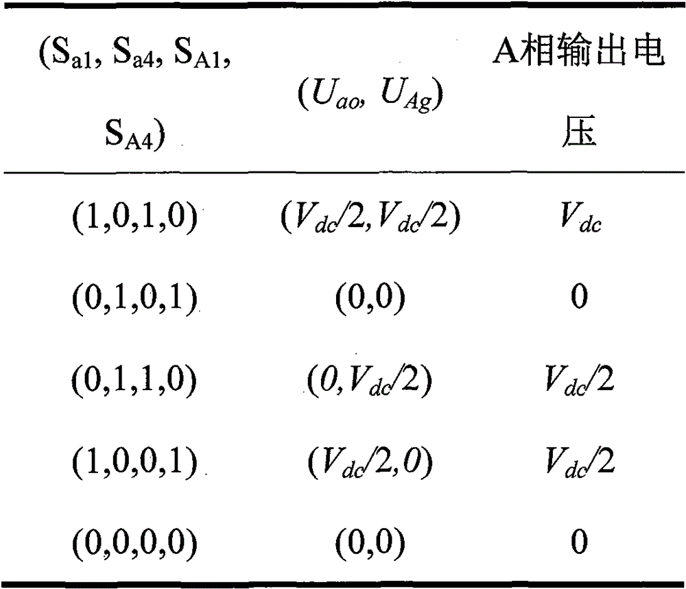
表1是A相开关状态与A桥臂输出电压关系;如表1所示,A相开关状态与A桥臂输出电压关系,可以满足三电平输出要求,表1中0表示开关处于开通状态,1表示开关处于关断状态;Table 1 shows the relationship between the A-phase switching state and the output voltage of the A bridge arm; as shown in Table 1, the relationship between the A-phase switching state and the A bridge arm output voltage can meet the three-level output requirements, and 0 in Table 1 indicates that the switch is in the open state , 1 means the switch is off;
表1 A相开关状态与A桥臂输出电压关系Table 1 The relationship between the switching state of phase A and the output voltage of the bridge arm of A

在三电平组合容错逆变电路正常工作时,每相的输出电压为上下桥臂输出电压的叠加经过滤波电容以及滤波电感输出三相正弦波;When the three-level combined fault-tolerant inverter circuit works normally, the output voltage of each phase is the superposition of the output voltage of the upper and lower bridge arms, and the three-phase sine wave is output through the filter capacitor and the filter inductor;
当A相上半桥臂发生故障时,将A相上桥臂从电路中切除,将A相上桥臂负载接入A相下桥臂输出端,此时A相桥臂作为两电平逆变电路输出;其他相某一侧桥臂发生故障时,处理方式类同;When the A-phase upper half bridge arm fails, the A-phase upper bridge arm is cut off from the circuit, and the A-phase upper bridge arm load is connected to the A-phase lower arm output terminal. At this time, the A-phase bridge arm is used as a two-level inverter. Change the circuit output; when the bridge arm on one side of the other phase fails, the processing method is similar;
当A、B相上半桥臂发生故障,将A、B相上桥臂从电路中切除,将A相上桥臂负载接入A相下桥臂输出端,B相上桥臂负载接入B相下桥臂输出端;其他两相桥臂发生故障时,处理方式类同;When the upper half bridge arm of phase A and B fails, remove the upper bridge arm of phase A and B from the circuit, connect the load of the upper arm of phase A to the output terminal of the lower arm of phase A, and connect the load of the upper arm of phase B to the output terminal of the lower arm of phase A. The output terminal of the lower arm of phase B; when the other two-phase arm fails, the processing method is similar;
当A、B、C相上半桥臂发生故障,将A、B、C相上桥臂从电路中切除,将A、B、C三相上桥臂负载接入A、B、C三相下桥臂输出端;When A, B, C-phase upper half bridge arm fails, cut A, B, C-phase upper bridge arm from the circuit, connect A, B, C three-phase upper bridge arm load to A, B, C three-phase The output terminal of the lower bridge arm;
当电路A相发生故障时,将A相整个电路切除,将B、C两相的电压参考信号调节成相位互差为90°的电压信号,即B相超前C相90°;When the phase A of the circuit fails, the entire circuit of the A phase is cut off, and the voltage reference signals of the B and C phases are adjusted to a voltage signal with a phase difference of 90°, that is, the B phase leads the C phase by 90°;
当电路B相发生故障时,将B相整个电路切除,将A、C两相的电压参考信号调节成相位互差为90°的电压信号,即A相超前C相90°;When the B-phase of the circuit fails, the entire circuit of the B-phase is cut off, and the voltage reference signals of the A and C phases are adjusted to a voltage signal with a phase difference of 90°, that is, the A-phase leads the C-phase by 90°;
当电路C相发生故障时,将C相整个电路切除,将A、B两相的电压参考信号调节成相位互差为90°的电压信号,即A相超前B相90°。When the C-phase of the circuit fails, the entire circuit of the C-phase is cut off, and the voltage reference signals of the A and B phases are adjusted to a voltage signal with a phase difference of 90°, that is, the A-phase leads the B-phase by 90°.
本发明在逆变电路正常工作时,利用变压器对三相输出电压波形进行优化;故障后,将故障桥臂切除,利用变压器将两相电压合成为三相进行输出,保证电路正常工作。三相三电平逆变电路容错拓扑对于单桥臂故障具有良好的容错功能,且控制与拓扑结构简单,易于实现。When the inverter circuit is working normally, the invention uses the transformer to optimize the three-phase output voltage waveform; after the fault, the faulty bridge arm is cut off, and the transformer is used to synthesize the two-phase voltage into three-phase output to ensure the normal operation of the circuit. The fault-tolerant topology of the three-phase three-level inverter circuit has a good fault-tolerant function for single-arm faults, and the control and topology are simple and easy to implement.
附图说明Description of drawings
图1是本发明逆变电路拓扑结构图;Fig. 1 is the topological structure diagram of inverter circuit of the present invention;
图2是逆变电路单臂故障的容错电路;Fig. 2 is the fault-tolerant circuit of the single-arm fault of the inverter circuit;
图3是逆变电路双臂故障的容错电路;Fig. 3 is the fault-tolerant circuit of the double-arm fault of the inverter circuit;
图4是逆变电路三臂故障的容错电路;Figure 4 is a fault-tolerant circuit for the three-arm fault of the inverter circuit;
图5是A相故障,拓扑结构容错方案及切除A相后变压器模块接线图,其中图5(a)示出A相故障拓扑重构方案,图5(b)示出A相故障变压器侧接线方案;Figure 5 is the A-phase fault, topology fault tolerance scheme and the wiring diagram of the transformer module after the A-phase is removed, in which Figure 5(a) shows the A-phase fault topology reconstruction scheme, and Figure 5(b) shows the A-phase fault transformer side wiring Program;
图6是B相故障,拓扑结构容错方案及切除B相后变压器模块接线图,其中图6(a)示出B相切除后电路重构拓扑,图6(b)示出B相故障变压器侧接线方案;Figure 6 is the B-phase fault, topology fault-tolerant scheme and the wiring diagram of the transformer module after the B-phase is removed. Figure 6(a) shows the circuit reconstruction topology after the B-phase is removed, and Figure 6(b) shows the B-phase fault transformer side. wiring scheme;
图7是C相故障,拓扑结构容错方案及切除C相后变压器模块接线图,其中图7(a)示出C相切除后电路重构拓扑,图7(b)示出C相故障变压器侧接线方案。Figure 7 is the C-phase fault, topology fault tolerance scheme and the wiring diagram of the transformer module after the C-phase is removed, in which Figure 7(a) shows the circuit reconstruction topology after the C-phase is removed, and Figure 7(b) shows the C-phase fault transformer side wiring scheme.
具体实施方式Detailed ways
为了使本发明的目的、技术方案以及优点更加清楚明白,以下结合附图和实施例,对本发明进行进一步详细说明。In order to make the objectives, technical solutions and advantages of the present invention clearer, the present invention will be further described in detail below with reference to the accompanying drawings and embodiments.
如图1所示,本发明三电平组合容错逆变电路的主电路拓扑分为两个模块,左边部分为三相桥臂容错模块,右边部分为变压器容错模块,分别用两个虚线框表示。两个模块的容错功能不同,能够满足逆变电路多种复杂情况下电路故障时的容错工作。As shown in Figure 1, the main circuit topology of the three-level combined fault-tolerant inverter circuit of the present invention is divided into two modules, the left part is the three-phase bridge arm fault-tolerant module, and the right part is the transformer fault-tolerant module, respectively represented by two dashed boxes . The fault-tolerant functions of the two modules are different, which can meet the fault-tolerant work of the inverter circuit when the circuit fails in various complex situations.
在三相桥臂容错模块中分为4个桥臂,第一桥臂为中位点调节桥臂,由自上而下的四个功率管S1、S2、S3、S4和它们及其各自的反并联二极管、以及钳位电容C组成;每个功率管的集电极接反并联二极管的负极,发射极接反并联二极管的正极,形成一个功率管单元,因此,自上而下共形成相串联的四个功率管单元:功率管S1单元、S2单元、S3单元和S4单元;其中,由上至下,功率管S1的集电极与电源正极相连,功率管S1的发射极与功率管S2的集电极相连,功率管S2的发射极与功率管S3的集电极相连,功率管S3的发射极与功率管S4的集电极相连,功率管S4的发射极接地;并且,钳位电容C的“+”端与功率管S1的发射极(也就是功率管S2的集电极)连接,钳位电容C的“-”端与功率管S3的发射极(也就是S4的集电极)连接;将功率管S2的发射极与功率管S3的集电极之间的连接点(以下将这样的连接点称为两个功率管的“中点”)定义为点O。In the three-phase bridge arm fault-tolerant module, it is divided into four bridge arms, the first bridge arm is the neutral point adjustment bridge arm, and the top-down four power tubes S 1 , S 2 , S 3 , S 4 and their It is composed of its respective anti-parallel diode and clamping capacitor C; the collector of each power tube is connected to the negative pole of the anti-parallel diode, and the emitter is connected to the positive pole of the anti-parallel diode to form a power tube unit. Therefore, from top to bottom A total of four power tube units connected in series are formed: power tube S1 unit, S2 unit, S3 unit and S4 unit ; wherein, from top to bottom, the collector of power tube S1 is connected to the positive pole of the power supply, and the power tube The emitter of S1 is connected with the collector of power tube S2 , the emitter of power tube S2 is connected with the collector of power tube S3, the emitter of power tube S3 is connected with the collector of power tube S4, the power The emitter of the tube S4 is grounded; and the "+" end of the clamping capacitor C is connected to the emitter of the power tube S1 ( that is, the collector of the power tube S2), and the "-" end of the clamping capacitor C is connected to The emitter of the power tube S3 (that is, the collector of S4 ) is connected; the connection point between the emitter of the power tube S2 and the collector of the power tube S3 (hereinafter such connection points are referred to as two The "midpoint") of the power tube is defined as point O.
三相桥臂容错模块中剩下的三个桥臂分别为三相输出桥臂,三个桥臂结构相同,以A相桥臂为例进行说明。A相桥臂自上而下由功率管Sa1、Sa4、SA1、SA4以及它们各自的反并联二极管组成,共形成自上而下的四个功率管单元:功率管Sa1单元、Sa4单元、SA1单元、SA4单元,四个功率管单元的连接方式与上述中位点调节桥臂的连接方式完全相同,不再累述。其中,将相串联的功率管Sa1单元和功率管Sa4单元称为A相桥臂的上桥臂,将相串联的功率管单元SA1和功率管SA4单元称为A相桥臂的下桥臂。a点为上桥臂功率管Sa1、Sa4的中点,A点为下桥臂功率管SA1、SA4的中点。作为上桥臂的延伸,滤波电感La、滤波电阻Ra相串联,在滤波电阻Ra后并联了一个滤波电容Ca;其中滤波电感La的正端与a点相连,负端与滤波电阻Ra相连,滤波电阻Ra的另一端与滤波电容Ca的正端相连,将滤波电容Ca的负端定义为点O1。作为下桥臂的延伸,滤波电感LA、滤波电阻RA相串联,在滤波电阻RA后并联了一个滤波电容CA;其中滤波电感LA的正端与A点相连,负端与滤波电阻RA相连,滤波电阻RA的另一端与滤波电容CA的正端相连,将滤波电感CA的负端定义为点O2。The remaining three bridge arms in the three-phase bridge arm fault-tolerant module are respectively three-phase output bridge arms, and the three bridge arms have the same structure. The A-phase bridge arm is taken as an example for illustration. The A-phase bridge arm is composed of power tubes S a1 , S a4 , S A1 , S A4 and their respective anti-parallel diodes from top to bottom, forming four power tube units from top to bottom: the power tube S a1 unit, The connection method of the S a4 unit, the S A1 unit, and the S A4 unit, and the four power tube units are exactly the same as the connection method of the above-mentioned neutral point adjustment bridge arm, and will not be repeated. Among them, the power tube S a1 unit and the power tube S a4 unit connected in series are called the upper bridge arm of the A-phase bridge arm, and the power tube unit S A1 and the power tube S A4 unit connected in series are called the upper arm of the A-phase bridge arm. Lower bridge arm. Point a is the midpoint of the power tubes S a1 and S a4 of the upper bridge arm, and point A is the midpoint of the power tubes S A1 and S A4 of the lower bridge arm. As an extension of the upper bridge arm, the filter inductor La and the filter resistor Ra are connected in series, and a filter capacitor C a is connected in parallel after the filter resistor Ra ; the positive end of the filter inductor La is connected to point a, and the negative end is connected to the filter The resistor Ra is connected, and the other end of the filter resistor Ra is connected to the positive end of the filter capacitor C a , and the negative end of the filter capacitor C a is defined as a point O 1 . As an extension of the lower bridge arm, the filter inductor LA and the filter resistor RA are connected in series, and a filter capacitor C A is connected in parallel after the filter resistor RA ; the positive end of the filter inductor LA is connected to point A , and the negative end is connected to the filter The resistor RA is connected, the other end of the filter resistor RA is connected with the positive end of the filter capacitor CA , and the negative end of the filter inductor CA is defined as point O 2 .
由于三相桥臂结构相同,所以在B、C两相的上桥臂中分别有滤波电感Lb、Lc,滤波电阻Rb、Rc,以及滤波电容Cb、Cc,所有滤波电容Ca、Cb、Cc的“-”端均接在一点即O1点。在B、C两相的下桥臂中分别有滤波电感LB、LC,滤波电阻RB、RC,以及滤波电容CB、CC,三相下桥臂的滤波电容CA、CB、CC的“-”端均接在O2点。A相上桥臂滤波电阻Ra通过连接变压器模块与A相负载LoadA与下桥臂RA串联在一起构成了回路。Since the structure of the three-phase bridge arms is the same, there are filter inductors L b , L c , filter resistors R b , R c , and filter capacitors C b , C c in the upper bridge arms of the B and C phases, respectively. All filter capacitors The "-" terminals of C a , C b , and C c are all connected to one point, that is, point O 1 . In the lower arms of the two phases B and C, there are respectively filter inductors LB and LC, filter resistors RB and RC, as well as filter capacitors C B and C C , and filter capacitors C A and C of the three-phase lower arms . The "-" ends of B and C are connected to the O 2 point. A-phase upper bridge arm filter resistance R a is connected in series with the A -phase load LoadA and the lower bridge arm RA to form a loop.
在三相桥臂容错模块中,定义U是A相上桥臂a点与O点之间的输出电压,UAg是A相下桥臂A点与接地点g之间的输出电压,Sa1-Sa6、SA1-SA6分别为上、下桥臂的6个功率开关管。三相输出电压分别由上下工作的两部分电路叠加。RX、LX、CX(X=a,b,c,A,B,C)分别为各相桥臂的滤波电阻、滤波电感和滤波电容。为了描述简单起见,现将三相桥臂容错模块中的三相输出桥臂各自的上桥臂统称为电路上部三桥臂,三相输出桥臂各自的下桥臂统称为电路下部三桥臂。In the three-phase bridge arm fault-tolerant module, it is defined that U is the output voltage between point a and point O of the upper bridge arm of phase A, U Ag is the output voltage between point A and ground point g of the lower bridge arm of phase A, and S a1 -S a6 , S A1 -S A6 are the 6 power switch tubes of the upper and lower bridge arms, respectively. The three-phase output voltage is superimposed by the upper and lower working circuits respectively. R X , L X , and C X (X=a, b, c, A, B, C) are respectively the filter resistance, filter inductance and filter capacitor of each phase bridge arm. For the sake of simplicity of description, the upper arms of the three-phase output bridge arms in the three-phase bridge arm fault-tolerant module are collectively referred to as the upper three bridge arms of the circuit, and the respective lower arms of the three-phase output bridge arms are collectively referred to as the lower three bridge arms of the circuit .
变压器容错模块为两组三相变压器,具体包括上桥臂三相变压器和下桥臂三相变压器,其中A相绕组副边有二组抽头,原副边变比T1a∶T2a1∶T2a2=1∶1∶0.5,B相绕组有三组抽头,原副边变比

变压器容错模块的两个变压器结构相同,下面以与上桥臂相连的变压器为例描述其结构。三相变压器的原边绕组由T1a、T1b、T1c三个绕组组成,三个绕组的“+”端分别与上桥臂a、b、c的滤波电阻输出端(即相应滤波电容的正端)相连,三个绕组的“-”端并在一起与O1点相连。变压器副边绕组众多,将依次详细说明,上桥臂变压器a相的副边绕组由三个抽头两组线圈组成,在三个抽头中第一个为“+”,最后一个为“-”,原边线圈与副边两个线圈的线圈匝数比分别为T1a∶T2a1∶T2a2=1∶1∶0.5;b相的副边绕组由四个抽头三组线圈组成,在四个抽头中第一个为“+”,最后一个为“-”,原边线圈与副边三个线圈的线圈匝数比分别为

本发明是对变电路结构的发明,其中功率管、变压器、二极管、电容、电感、电阻的大小及型号均由逆变电路的输出功率决定,故此对其不作限定。在本发明的一个实施例中,直流电压源为270V,功率管选用IGBT,滤波电感La=2mH,滤波电容Ca=40μF,滤波电阻Ra=25mΩ)The present invention is an invention of the inverter circuit structure, wherein the size and model of the power tube, transformer, diode, capacitor, inductor and resistor are determined by the output power of the inverter circuit, so it is not limited. In one embodiment of the present invention, the DC voltage source is 270V, the power tube is selected from IGBT, the filter inductor L a =2mH, the filter capacitor C a =40μF, and the filter resistance R a =25mΩ)
LoadA,LoadB,LoadC分别为三相负载,在每一相输出中,负载通过上下桥臂变压器连接。当电路正常工作时,每一相上下桥臂的控制信号不同,需根据不同控制方法选择合适控制信号。当某一相桥臂上桥臂或下桥臂故障时,电路将把故障桥臂切除,同时将该相正常桥臂的输出加在故障桥臂的变压器侧,使得该故障桥臂变成两电平逆变电路输出。LoadA, LoadB, and LoadC are three-phase loads respectively. In each phase output, the loads are connected through the upper and lower bridge arm transformers. When the circuit is working normally, the control signals of the upper and lower bridge arms of each phase are different, and appropriate control signals need to be selected according to different control methods. When the upper arm or lower arm of a certain phase arm fails, the circuit will cut off the faulty arm, and at the same time add the output of the normal arm of the phase to the transformer side of the fail arm, so that the fail arm becomes two arms. Level inverter circuit output.
三相桥臂容错模块主要是实现某一相或多相桥臂单管或多管故障的容错功能,而变压器容错模块主要是实现某一相整个桥臂出现故障后,由剩余两相电路实现输出三相电压的输出功能。The three-phase bridge arm fault-tolerant module mainly realizes the fault-tolerant function of single-tube or multi-tube faults of a certain phase or multi-phase bridge arm, while the transformer fault-tolerant module mainly realizes the failure of a certain phase and the whole bridge arm by the remaining two-phase circuits. Output function to output three-phase voltage.
表1是A相开关状态与A桥臂输出电压关系。如表1所示,A相开关状态与A桥臂输出电压关系,可以满足三电平输出要求,表1中0表示开关处于开通状态,1表示开关处于关断状态。Table 1 is the relationship between the A-phase switching state and the output voltage of the A bridge arm. As shown in Table 1, the relationship between the A-phase switching state and the output voltage of the A bridge arm can meet the three-level output requirements. In Table 1, 0 indicates that the switch is on, and 1 indicates that the switch is off.
表1 A相开关状态与A桥臂输出电压关系Table 1 The relationship between the switching state of phase A and the output voltage of the bridge arm of A

如图1所示电路正常工作时,每相的输出电压为上下桥臂输出电压的叠加经过滤波电容以及滤波电感输出三相正弦波。When the circuit shown in Figure 1 works normally, the output voltage of each phase is the superposition of the output voltages of the upper and lower bridge arms, and the three-phase sine wave is output through the filter capacitor and the filter inductor.
当电路单相桥臂发生故障时,如A相上半桥臂发生故障,拓扑重构方案如图2所示,将A相上桥臂从电路中切除,将A相上桥臂负载接入A相下桥臂输出端,图中用虚线表示连接线。此时A相桥臂作为两电平逆变电路输出。其他相某一侧桥臂发生故障时处理方式相同,虚线表示电路重构部分。When the single-phase bridge arm of the circuit fails, such as the failure of the A-phase upper half bridge arm, the topology reconstruction scheme is shown in Figure 2. The A-phase upper arm is removed from the circuit, and the A-phase upper arm load is connected. The output end of the lower bridge arm of phase A, the connection line is represented by the dotted line in the figure. At this time, the A-phase bridge arm is output as a two-level inverter circuit. When the bridge arm on one side of the other phase fails, the processing method is the same, and the dotted line represents the circuit reconstruction part.
当电路两相桥臂发生故障时,如A、B相上半桥臂发生故障,拓扑重构方案如图3所示,将A、B相上桥臂从电路中切除,将A相上桥臂负载接入A相下桥臂输出端,图中用虚线表示连接线,B相上桥臂负载接入B相下桥臂输出端。When the two-phase bridge arm of the circuit fails, such as the failure of the upper half bridge arm of the A and B phases, the topology reconstruction scheme is shown in Figure 3. The arm load is connected to the output end of the lower arm of phase A, the dotted line in the figure represents the connection line, and the load of the upper arm of phase B is connected to the output end of the lower arm of phase B.
当电路三相桥臂发生故障时,如A、B、C相上半桥臂发生故障,拓扑重构方案如图4所示,将A、B、C相上桥臂从电路中切除,将A、B、C三相上桥臂负载接入A、B、C三相下桥臂输出端,图中用虚线表示连接线。When the three-phase bridge arm of the circuit fails, such as the failure of the upper half bridge arm of the A, B, and C phases, the topology reconstruction scheme is shown in Figure 4. The upper bridge arm of the A, B, and C phases is removed from the circuit, and the A, B, C three-phase upper bridge arm loads are connected to A, B, C three-phase lower bridge arm outputs, and the dotted line in the figure represents the connection line.
当电路A相发生故障时,将A相整个电路切除,将B、C两相的电压参考信号调节成相位互差为90°的电压信号,即B相超前C相90°。拓扑结构容错方案及切除A相后变压器模块接线如图5所示,图中用虚线表示连接线。When the A-phase of the circuit fails, the entire circuit of the A-phase is cut off, and the voltage reference signals of the B and C phases are adjusted to a voltage signal with a phase difference of 90°, that is, the B-phase leads the C-phase by 90°. The topology fault-tolerant scheme and the connection of the transformer module after removing the A-phase are shown in Figure 5, and the connection line is represented by a dotted line in the figure.
当电路B相发生故障时,将B相整个电路切除,将A、C两相的电压参考信号调节成相位互差为90°的电压信号,即A相超前C相90°,拓扑结构容错方案及切除B相后变压器模块接线如图6所示,图中用虚线表示连接线。When the B-phase of the circuit fails, the entire circuit of the B-phase is cut off, and the voltage reference signals of the A and C phases are adjusted to a voltage signal with a phase difference of 90°, that is, the A-phase leads the C-phase by 90°, and the topology is fault-tolerant scheme. And the connection of the transformer module after removing the B phase is shown in Figure 6, and the connection line is represented by a dotted line in the figure.
当电路C相发生故障时,将C相整个电路切除,将A、B两相的电压参考信号调节成相位互差为90°的电压信号,即A相超前B相90°,拓扑结构容错方案及切除C相后变压器模块接线如图7所示,图中用虚线表示连接线。When the C-phase of the circuit fails, the entire circuit of the C-phase is cut off, and the voltage reference signals of the A and B phases are adjusted to a voltage signal with a phase difference of 90°, that is, the A-phase leads the B-phase by 90°, and the topology is fault-tolerant scheme. And the connection of the transformer module after removing the C phase is shown in Figure 7, and the connection line is represented by a dotted line in the figure.
Claims (4)


Priority Applications (1)
| Application Number | Priority Date | Filing Date | Title |
|---|---|---|---|
| CN201811200844.5A CN109347344B (en) | 2018-09-28 | 2018-09-28 | Three-level combined fault-tolerant inverter circuit |
Applications Claiming Priority (1)
| Application Number | Priority Date | Filing Date | Title |
|---|---|---|---|
| CN201811200844.5A CN109347344B (en) | 2018-09-28 | 2018-09-28 | Three-level combined fault-tolerant inverter circuit |
Publications (2)
| Publication Number | Publication Date |
|---|---|
| CN109347344A CN109347344A (en) | 2019-02-15 |
| CN109347344B true CN109347344B (en) | 2020-12-25 |
Family
ID=65309414
Family Applications (1)
| Application Number | Title | Priority Date | Filing Date |
|---|---|---|---|
| CN201811200844.5A Active CN109347344B (en) | 2018-09-28 | 2018-09-28 | Three-level combined fault-tolerant inverter circuit |
Country Status (1)
| Country | Link |
|---|---|
| CN (1) | CN109347344B (en) |
Families Citing this family (4)
| Publication number | Priority date | Publication date | Assignee | Title |
|---|---|---|---|---|
| CN111262421B (en) * | 2020-02-28 | 2024-07-02 | 致瞻科技(上海)有限公司 | Isolated three-phase fault-tolerant circuit, control method, control system and storage medium |
| EP3989429A1 (en) * | 2020-10-22 | 2022-04-27 | General Electric Technology GmbH | Electrical assembly |
| CN113595423B (en) * | 2021-07-29 | 2024-08-02 | 上海海事大学 | Fault-tolerant topological structure of three-phase cascade multi-level inverter and control method |
| CN121689779B (en) * | 2026-02-10 | 2026-04-28 | 国网江苏省电力有限公司电力科学研究院 | A method and system for multi-tube fault-tolerant operation of a large-capacity offshore wind converter |
Citations (4)
| Publication number | Priority date | Publication date | Assignee | Title |
|---|---|---|---|---|
| JP2002209314A (en) * | 2001-01-11 | 2002-07-26 | Toshiba Corp | Substation equipment |
| CN1477656A (en) * | 2003-06-18 | 2004-02-25 | 中国石化集团河南石油勘探局水电厂 | Fault phase compensation combined transformer |
| CN104333208A (en) * | 2014-10-27 | 2015-02-04 | 中南大学 | Device for handling open-circuit fault of three-section bridge converter circuit and fault diagnosis method |
| CN105319465A (en) * | 2015-10-21 | 2016-02-10 | 清华大学 | Power grid voltage fault simulation device |
Family Cites Families (1)
| Publication number | Priority date | Publication date | Assignee | Title |
|---|---|---|---|---|
| US7737667B2 (en) * | 2004-10-14 | 2010-06-15 | Utility Systems Technologies, Inc. | 3-phase electronic tap changer commutation and device |
-
2018
- 2018-09-28 CN CN201811200844.5A patent/CN109347344B/en active Active
Patent Citations (4)
| Publication number | Priority date | Publication date | Assignee | Title |
|---|---|---|---|---|
| JP2002209314A (en) * | 2001-01-11 | 2002-07-26 | Toshiba Corp | Substation equipment |
| CN1477656A (en) * | 2003-06-18 | 2004-02-25 | 中国石化集团河南石油勘探局水电厂 | Fault phase compensation combined transformer |
| CN104333208A (en) * | 2014-10-27 | 2015-02-04 | 中南大学 | Device for handling open-circuit fault of three-section bridge converter circuit and fault diagnosis method |
| CN105319465A (en) * | 2015-10-21 | 2016-02-10 | 清华大学 | Power grid voltage fault simulation device |
Non-Patent Citations (1)
| Title |
|---|
| MLD模型下逆变电路改进型直接功率预测控制;韩建定;《空军工程大学学报》;20180228;第66-70页 * |
Also Published As
| Publication number | Publication date |
|---|---|
| CN109347344A (en) | 2019-02-15 |
Similar Documents
| Publication | Publication Date | Title |
|---|---|---|
| CN109347344B (en) | Three-level combined fault-tolerant inverter circuit | |
| CN103269171B (en) | High power cascade type diode H-bridge unit power factor rectifier | |
| CN109067218B (en) | A solid-state transformer topology construction method based on multi-level sub-modules | |
| CN111276992A (en) | Modular multi-level alternating current-direct current conversion system | |
| CN104079195B (en) | Power conversion circuit and power conversion system | |
| CN108832825A (en) | A kind of multiport electric power electric transformer topology of high power density | |
| CN103280994A (en) | High-power cascaded multi-level bridgeless current transformer | |
| CN103280984A (en) | Cascade connection type current transformer based on single-stage power transformation module | |
| CN107134926A (en) | A kind of modular electric energy router combinational circuit | |
| CN109286330B (en) | High-current high-power converter | |
| CN107104600B (en) | Modular multilevel converter and electric power electric transformer | |
| CN108847777B (en) | Isolated modular cascade converter based on high-frequency chain technology | |
| WO2018141283A1 (en) | Bridge-free pfc circuit | |
| TW201814998A (en) | Power converting device, power supply, and control method thereof | |
| CN103765754B (en) | There is the invertor of coupling inductance | |
| WO2018108140A1 (en) | Modular power supply system | |
| CN105024571A (en) | Three-phase inverter circuit | |
| CN107546975B (en) | A kind of isolated form high pressure DC/AC converter and its wide scope Regulation Control method | |
| CN111786579A (en) | Cascaded Multilevel Rectifiers with Common HVDC Bus and Control Strategy | |
| CN111490694A (en) | Automatic neutral point voltage balancing circuit for I-type three-level bus in converter | |
| CN105553314A (en) | Hybrid modular multilevel converter topological structure based on three-level submodules and two-level submodules | |
| Salehahari et al. | A new structure of multilevel inverters based on coupled inductors to increase the output current | |
| CN114499244B (en) | Medium-high voltage five-level rectifier and direct-current capacitor voltage balance control strategy | |
| CN112688576B (en) | Five-level rectifier with public high-voltage direct-current bus and control strategy | |
| CN102664547B (en) | Parallel cascade inverter |
Legal Events
| Date | Code | Title | Description |
|---|---|---|---|
| PB01 | Publication | ||
| PB01 | Publication | ||
| SE01 | Entry into force of request for substantive examination | ||
| SE01 | Entry into force of request for substantive examination | ||
| GR01 | Patent grant | ||
| GR01 | Patent grant |