CN1096148C - Signal encoding method and apparatus - Google Patents
Signal encoding method and apparatus Download PDFInfo
- Publication number
- CN1096148C CN1096148C CN96121964A CN96121964A CN1096148C CN 1096148 C CN1096148 C CN 1096148C CN 96121964 A CN96121964 A CN 96121964A CN 96121964 A CN96121964 A CN 96121964A CN 1096148 C CN1096148 C CN 1096148C
- Authority
- CN
- China
- Prior art keywords
- signal
- encoding
- frequency
- band
- frequency bands
- Prior art date
- Legal status (The legal status is an assumption and is not a legal conclusion. Google has not performed a legal analysis and makes no representation as to the accuracy of the status listed.)
- Expired - Fee Related
Links
Images









Classifications
-
- G—PHYSICS
- G10—MUSICAL INSTRUMENTS; ACOUSTICS
- G10L—SPEECH ANALYSIS TECHNIQUES OR SPEECH SYNTHESIS; SPEECH RECOGNITION; SPEECH OR VOICE PROCESSING TECHNIQUES; SPEECH OR AUDIO CODING OR DECODING
- G10L19/00—Speech or audio signals analysis-synthesis techniques for redundancy reduction, e.g. in vocoders; Coding or decoding of speech or audio signals, using source filter models or psychoacoustic analysis
- G10L19/02—Speech or audio signals analysis-synthesis techniques for redundancy reduction, e.g. in vocoders; Coding or decoding of speech or audio signals, using source filter models or psychoacoustic analysis using spectral analysis, e.g. transform vocoders or subband vocoders
- G10L19/0212—Speech or audio signals analysis-synthesis techniques for redundancy reduction, e.g. in vocoders; Coding or decoding of speech or audio signals, using source filter models or psychoacoustic analysis using spectral analysis, e.g. transform vocoders or subband vocoders using orthogonal transformation
-
- G—PHYSICS
- G10—MUSICAL INSTRUMENTS; ACOUSTICS
- G10L—SPEECH ANALYSIS TECHNIQUES OR SPEECH SYNTHESIS; SPEECH RECOGNITION; SPEECH OR VOICE PROCESSING TECHNIQUES; SPEECH OR AUDIO CODING OR DECODING
- G10L19/00—Speech or audio signals analysis-synthesis techniques for redundancy reduction, e.g. in vocoders; Coding or decoding of speech or audio signals, using source filter models or psychoacoustic analysis
- G10L19/02—Speech or audio signals analysis-synthesis techniques for redundancy reduction, e.g. in vocoders; Coding or decoding of speech or audio signals, using source filter models or psychoacoustic analysis using spectral analysis, e.g. transform vocoders or subband vocoders
- G10L19/0204—Speech or audio signals analysis-synthesis techniques for redundancy reduction, e.g. in vocoders; Coding or decoding of speech or audio signals, using source filter models or psychoacoustic analysis using spectral analysis, e.g. transform vocoders or subband vocoders using subband decomposition
- G10L19/0208—Subband vocoders
-
- G—PHYSICS
- G10—MUSICAL INSTRUMENTS; ACOUSTICS
- G10L—SPEECH ANALYSIS TECHNIQUES OR SPEECH SYNTHESIS; SPEECH RECOGNITION; SPEECH OR VOICE PROCESSING TECHNIQUES; SPEECH OR AUDIO CODING OR DECODING
- G10L19/00—Speech or audio signals analysis-synthesis techniques for redundancy reduction, e.g. in vocoders; Coding or decoding of speech or audio signals, using source filter models or psychoacoustic analysis
- G10L19/04—Speech or audio signals analysis-synthesis techniques for redundancy reduction, e.g. in vocoders; Coding or decoding of speech or audio signals, using source filter models or psychoacoustic analysis using predictive techniques
-
- G—PHYSICS
- G10—MUSICAL INSTRUMENTS; ACOUSTICS
- G10L—SPEECH ANALYSIS TECHNIQUES OR SPEECH SYNTHESIS; SPEECH RECOGNITION; SPEECH OR VOICE PROCESSING TECHNIQUES; SPEECH OR AUDIO CODING OR DECODING
- G10L19/00—Speech or audio signals analysis-synthesis techniques for redundancy reduction, e.g. in vocoders; Coding or decoding of speech or audio signals, using source filter models or psychoacoustic analysis
- G10L19/04—Speech or audio signals analysis-synthesis techniques for redundancy reduction, e.g. in vocoders; Coding or decoding of speech or audio signals, using source filter models or psychoacoustic analysis using predictive techniques
- G10L19/06—Determination or coding of the spectral characteristics, e.g. of the short-term prediction coefficients
- G10L19/07—Line spectrum pair [LSP] vocoders
Landscapes
- Engineering & Computer Science (AREA)
- Physics & Mathematics (AREA)
- Computational Linguistics (AREA)
- Signal Processing (AREA)
- Health & Medical Sciences (AREA)
- Audiology, Speech & Language Pathology (AREA)
- Human Computer Interaction (AREA)
- Acoustics & Sound (AREA)
- Multimedia (AREA)
- Spectroscopy & Molecular Physics (AREA)
- Compression, Expansion, Code Conversion, And Decoders (AREA)
- Transmission Systems Not Characterized By The Medium Used For Transmission (AREA)
Abstract
对输入信号,例如宽范围语音信号进行编码的方法和装置,其中可用不同的位率进行多种译码操作,以便使甚至用低位率再现的声音的变差减至最小。该信号编码方法包括,波段分离步骤,用于将输入信号分离成若干波段,和依据各波段中的信号特征以不同方法对各波段信号进行编码的方法。特别是,低范围侧信号通过低通滤波器102从端101输入的输入信号中取出,和通过LPC分解量化单元130进行LPC分解。

Method and apparatus for encoding an input signal, such as a wide-range speech signal, in which multiple decoding operations can be performed at different bit rates in order to minimize the degradation of the reproduced sound even with low bit rates. The signal encoding method includes a band separation step for separating the input signal into several bands, and a method for encoding the signals of each band in different ways according to the signal characteristics in each band. In particular, the low-range side signal is taken out from the input signal input at the terminal 101 through the low-pass filter 102, and subjected to LPC decomposition through the LPC decomposition and quantization unit 130.
Description
本发明涉及对输入信号,例如,宽范围的语音信号,进行编码的方法和装置,特别涉及一种信号编码方法和装置,其中频谱被分离为作为语音来说能够获得足够清晰度的电话波段和该剩余的波段,其中的信号编码能够通过与相关的电话波段那样长的独立码加以实现。The present invention relates to a method and apparatus for encoding an input signal, such as a wide-range speech signal, and more particularly to a method and apparatus for encoding a signal in which the frequency spectrum is separated into telephone bands and The remaining bands, in which the signal encoding can be realized by independent codes as long as the relevant telephone bands.
现在已知通过利用对声音信号的统计特性和人的音质特点对包括语音和声学信号的音频信号进行压缩的各种方法。编码方法可以粗分为时间轴编码,频率轴编码和分解合成编码。Various methods are known for compressing audio signals including speech and acoustic signals by utilizing statistical properties of the sound signal and characteristics of human voice quality. Coding methods can be roughly classified into time-axis coding, frequency-axis coding, and decomposition-synthesis coding.
用于对语音信号等进行高效编码的已有技术中,有谐波编码,正弦分解编码,例如,多波段的激励(MBE)编码,付波段编码(SBC),线性予测码(LPC),离散余弦变换(DCT),改进的DCT(MDCT)和快速付利叶变换(FFT)。Among the existing technologies for efficient coding of speech signals, there are harmonic coding and sinusoidal decomposition coding, for example, multi-band excitation (MBE) coding, sub-band coding (SBC), linear predictive coding (LPC), Discrete Cosine Transform (DCT), Modified DCT (MDCT) and Fast Fourier Transform (FFT).
迄今已知的还有,在编码的前将输入信号分离为若干个波段的编码技术。然而,由于对低频范围的编码是采用对高频范围编码的相同的统一方法,这其中有这样的原因存在,适于低频范围信号的编码方法对于高频范围信号的编码效率则不足,反之亦然。特别是,当信号以低位率被传输时,最佳的编码偶尔也不能进行。Coding techniques are also known hitherto in which the input signal is split into several bands prior to coding. However, since the low frequency range is coded using the same uniform method as the high frequency range, there is a reason why coding methods suitable for low frequency range signals are not sufficiently efficient for high frequency range signals, and vice versa. Of course. In particular, when signals are transmitted at low bit rates, optimal encoding occasionally fails.
虽然现在在使用中各种信号译码装置被设计成以多种不同位率操作,对于不同位率使用不同的装置是很不方便的,也就是希望能使用单一的装置对若干不同位率的信号进行编码和译码。Although various signal decoding devices in use are designed to operate at many different bit rates, it is inconvenient to use different devices for different bit rates, that is, it is desirable to use a single device for several different bit rates. Signals are encoded and decoded.
其间,当前最迫切的是,接收具有高位率的自身具有可测量性的位流时,如果位流被直接译码,可得到高质量信号,然而,如果对位流的指定段译码,则产生低声音质量的信号。Among them, the most urgent thing at present is that when receiving a bit stream with a high bit rate and its own scalability, if the bit stream is directly decoded, a high-quality signal can be obtained, however, if a specified segment of the bit stream is decoded, then Produces a signal with low sound quality.
至此,将被处理的信号在编码侧被粗略量化,以产生低位率的位流,对该位流而言,在量化中产生的量化误差被进一步加以量化并加于该低位率的位流上,以产生高位率的位流。在此情况,如果编码方法实质上保持一样,那么位流能具有如上所述的可测量性,那就是,当低位率信号能被取出再现并对位流的部分译码,那么,通过译码该高位率位流就可直接获得高质量信号。So far, the signal to be processed is roughly quantized on the encoding side to generate a low bit rate bit stream, and for this bit stream, the quantization error generated in the quantization is further quantized and added to the low bit rate bit stream , to generate a high bit rate bit stream. In this case, if the encoding method remains substantially the same, the bitstream can have scalability as described above, that is, when a low bit rate signal can be taken out for reproduction and decoded for part of the bitstream, then, by decoding This high bit rate bit stream can directly obtain a high quality signal.
然而,当维持有可测量性时,如果希望对例如2kbps,6kps和16kbps的3位率的语音进行编码的话,则不容易构成上述完整的全包括的关系。However, if it is desired to encode speech at 3 bit rates such as 2 kbps, 6 kbps and 16 kbps while maintaining scalability, it is not easy to form the above-mentioned complete all-inclusive relationship.
即,对于尽可能的高信号质量的编码来说,波形编码最好用高位率进行,如果波形编码不能平滑地实现,那么编码将利用用于低位率的模式进行。在上述包括的关系中,由于用于编码的信息的差别,高位率中包含了不能实现的低位率。That is, for encoding with the highest possible signal quality, waveform encoding is preferably performed with a high bit rate, and if waveform encoding cannot be achieved smoothly, encoding will be performed using a mode for a low bit rate. In the above included relationship, due to the difference in information used for encoding, a low bit rate that cannot be realized is contained in a high bit rate.
从而本发明的目的是提供一种语音编码方法和装置,其中,用于编码的波段分离中,用少量位数就能产生高质量的播放语音,和对于予置波段的信号编码,例如电话波段,能用单独的码实现。Thereby the object of the present invention is to provide a kind of speech coding method and device, wherein, in the band separation that is used for coding, just can produce high-quality playback speech with a small number of bits, and for the signal coding of preset band, for example telephone band , can be implemented with a single code.
本发明的另一个目的是提供一种用于多路编码的信号的方法,其中,由于位率上的重大差别而不能通过同一方法编码的若干信号使之适合于尽可能多的共同信息并通过保证有测量性的实质不同的方法进行编码。Another object of the present invention is to provide a method for multiplexing encoded signals, wherein several signals which cannot be encoded by the same method due to significant differences in bit rates are adapted to as much common information as possible and passed through Guaranteed to be coded with substantially different methods of measurement.
本发明还有另一个目的是提供一种利用用于多路编码的信号的多路方法的信号编码装置。Still another object of the present invention is to provide a signal encoding apparatus utilizing a multiplexing method for multiplexing encoded signals.
另外,所提供的信号编码方法包括将输入信号分离成若干波段并依据各波段的信号特征以不同的方法,对各波段的信号进行编码的波段分离步骤。In addition, the signal encoding method provided includes a band separation step of separating the input signal into several bands and encoding the signals of each band in different ways according to the signal characteristics of each band.
另一方面,本发明提供的用于多路编码的信号的方法和装置具有若干语音编码装置,依次具有的装置有,用于对在利用第1位率对输入信号进行第1编码的基础上获得的第1编码的信号和对输入信号进行第2编码的基础上获得的第2编码的信号进行多路的装置,和用于多路第1编码的信号和第2编码的信号中除了与第1编码信号共同占有的部分之外的部分的装置。第2编码具有仅仅和第1编码的一部分公共的一部分并没同第1编码公共的部分。该第2编码利用的是与用于第1编码的位率不同的第2位率。On the other hand, the method and device for multi-channel coded signals provided by the present invention have a plurality of speech coding devices, and the devices provided in sequence are used to perform a first coding on an input signal using a first bit rate. A device for multiplexing the first coded signal obtained on the basis of the second coded input signal and the second coded signal obtained on the basis of the second coded signal, and for multiplexing the first coded signal and the second coded signal except for the A device for a portion other than the portion shared by the first coded signal. The second code has only a part in common with a part of the first code and no part in common with the first code. This second encoding uses a second bit rate different from the bit rate used for the first encoding.
根据本发明,输入信号被分离成若干波段和这样被分离的各波段的信号依据各分离波段的信号特征以不同的方式被编码。译码器能以不同速率操作,对于每一波段能以最佳效率进行编码,这样就改进了编码效率。According to the invention, an input signal is separated into several bands and the signals of the thus separated bands are coded differently depending on the signal characteristics of the separate bands. The decoder can operate at different rates to encode at optimum efficiency for each band, thus improving coding efficiency.
通过在波段中的一个的较低一侧的信号上进行短项预测,以确定短项预测余项,在这样确定短项预测余项的基础上进行长项预测,对这样确定的长项预测余项进行正交变换,这样达到较高的编码效率并可实现高质量的语音再现。By performing short term prediction on a signal on the lower side of one of the bands to determine a short term prediction remainder, performing a long term prediction on the basis of thus determining the short term prediction remainder, and performing a long term prediction on the thus determined long term The remaining items are subjected to orthogonal transformation, so as to achieve higher coding efficiency and realize high-quality speech reproduction.
还有,根据本发明,要取出至少一个波段,将这样取出的波段信号正交变换为频率域信号。该正交变换信号在频率轴上被移动到另一位置或另一波段,随后逆正交变换为时间域信号,该时间域信号被编码。这样任意频率波段的信号被取出并反转为低范围一侧,以便用低采样频率进行编码。Also, according to the present invention, at least one band is extracted, and the thus extracted band signal is orthogonally transformed into a frequency domain signal. The orthogonally transformed signal is shifted to another position or another band on the frequency axis, and then inversely orthogonally transformed into a time domain signal, which is encoded. In this way, the signal of any frequency band is taken out and inverted to the low-range side for encoding with a low sampling frequency.
另外,从任意频率可以产生任意频率宽度的付波段,以便于用两倍于频率宽度的采样频率加以处理,这样能使得灵活处理的应用。In addition, sub-bands of arbitrary frequency width can be generated from any frequency, so as to be processed with a sampling frequency twice the frequency width, which enables flexible processing applications.
图1是用于执行本发明编码方法的语音信号编码装置的基本结构的方框图;Fig. 1 is the block diagram that is used to carry out the basic structure of the speech signal encoding device of encoding method of the present invention;
图2是用于描述语音信号译码装置的基本结构的方框图;Fig. 2 is a block diagram for describing the basic structure of speech signal decoding device;
图3是另一种语音信号编码装置的结构的方框图;Fig. 3 is the block diagram of the structure of another kind of speech signal encoding device;
图4是描述被传输的编码数据的位流的可测量性;Figure 4 is a graph describing the scalability of the bitstream of encoded data being transmitted;
图5是根据本发明的编码一侧的整个系统的简略方框图;Fig. 5 is a simplified block diagram of the whole system according to the encoding side of the present invention;
图6A、6B和6C是用于编码和译码的主要操作的周期和相位;Figures 6A, 6B and 6C are the cycles and phases of the main operations for encoding and decoding;
图7A和7B是MSDCT系数的矢量量化;7A and 7B are vector quantization of MSDCT coefficients;
图8A和8B是应用于后滤波器输出的窗口功能的举例;8A and 8B are examples of window functions applied to the output of the post filter;
图9是具有两类码本的矢量量化装置;Fig. 9 is a vector quantization device with two types of codebooks;
图10是具有两类码本的矢量量化装置的详细结构的方框图;Fig. 10 is a block diagram of a detailed structure of a vector quantization device with two types of codebooks;
图11是具有两类码本的11H矢量量化装置的另一详细结构的方框图;Fig. 11 is a block diagram of another detailed structure of the 11H vector quantization device with two types of codebooks;
图12是用于频率转换的编码器的结构方框图;Fig. 12 is a structural block diagram of an encoder for frequency conversion;
图13A、13B是描述帧分离和重叠和加操作;13A, 13B describe frame separation and overlapping and adding operations;
图14A,14B和14C是描述在频率轴上的频率举例;14A, 14B and 14C are examples of frequencies described on the frequency axis;
图15A和15B是描述在频率轴上的数据位移;Figures 15A and 15B describe the data displacement on the frequency axis;
图16是用于频率转换的译码器的结构方框图;Fig. 16 is a structural block diagram of a decoder for frequency conversion;
图17A,17B和17C是在频率轴上频移的另一举例;17A, 17B and 17C are another example of frequency shift on the frequency axis;
图18是利用本发明语音编码装置的便携终端的传输一侧的结构方框图;Fig. 18 is a structural block diagram of the transmission side of the portable terminal utilizing the speech encoding device of the present invention;
图19是与利用与图18相关的语音信号译码装置的便携终接收侧的结构方框图。FIG. 19 is a block diagram showing the configuration of a portable terminal receiving side utilizing the speech signal decoding apparatus related to FIG. 18. FIG.
现在详细描述本发明的最佳实施例。The preferred embodiment of the present invention will now be described in detail.
图1是用于执行本发明语音编码方法的宽范围语音信号的编码装置(编码器)。FIG. 1 is an encoding device (encoder) for wide-range speech signals for carrying out the speech encoding method of the present invention.
图1所示编码器的基本概念是,将输入信号分离为若干波段和分离的波段信号依各自波段的信号特征以不同方式编码。特别是,输入语音信号的宽范围的频谱被分离为若干波段,即能达到对于语音来说足够清晰度的电话波段,和相关于电话波段较高侧波段。在短项预测,例如,在随后将通过例如音调(pitch)预测的长项预测的线性预测编码(LPC)之后,该较低波段的信号,即电话波段被正交变换,和,在正交变换获得的系数利用感性加权矢量量化加以处理。相关于长项预测的信息,例如音调或音调增益,或代表短项预测系数的参数,例如LPC系数,也被加以量化。高于电话波段的波段信号利用短项预测处理,然后在时间轴上直接矢量量化。The basic concept of the encoder shown in Figure 1 is to separate the input signal into several bands and to encode the separated band signals in different ways according to the signal characteristics of the respective bands. In particular, the wide-range frequency spectrum of the input speech signal is separated into several bands, namely the telephone band, which achieves sufficient intelligibility for speech, and the upper side bands relative to the telephone band. After short-term prediction, for example, after linear predictive coding (LPC) which will be followed by long-term prediction such as pitch prediction, the signal of the lower band, i.e. the telephone band, is orthogonally transformed, and, in the quadrature The transformed coefficients are processed using perceptually weighted vector quantization. Information related to long-term predictions, such as pitch or pitch gain, or parameters representing short-term prediction coefficients, such as LPC coefficients, are also quantized. Signals in bands above the telephone band are processed using short-term prediction and then vector quantized directly on the time axis.
改进的DCT(MDCT)被用作为正交变换。转换长度被弄短是为了便于对矢量量化的加权。另外,转换长度被置于2N,即等于2的幂的值,以便使得能利用快速付利叶变换(FFT)达到高处理速度。用于对正交转换系数的矢量量化计算加权和用于对短项预测计算余项(类似于对后滤波)的LPC系数是来自在当前帧确定的LPC系数和在过去帧确定的那些被平滑插入的LPC系数,这样的LPC系数对于分解每个付帧将是最佳的。在进行长项预测中,对每帧执行一定次数的预测或插入,其结果的音调延迟或音调增益被直接量化或找到差后量化。另外,还可传输标志指定的插入方法。对于预测余项该随着预测次数(频率)增加而变小的变更来说,对于正交变换系数的差的量化执行多级矢量量化。另外,仅利用分离波段中单一波段的参数用于使通过单一的编码的位流的全部或部分以不同的位率的若干个译码操作。Modified DCT (MDCT) is used as the orthogonal transform. The conversion length is shortened to facilitate the weighting of the vector quantization. In addition, the transform length is set to 2 N , a value equal to a power of 2, in order to enable a high processing speed using Fast Fourier Transform (FFT). The LPC coefficients used to calculate the weights for the vector quantization of the orthogonal transform coefficients and for the residuals for the short-term prediction (similar to post-filtering) are derived from the LPC coefficients determined at the current frame and those determined at past frames are smoothed interpolated LPC coefficients which would be optimal for decomposing each sub-frame. In performing long-term prediction, a certain number of predictions or interpolations are performed per frame, and the resulting pitch delay or pitch gain is directly quantized or quantized after finding a difference. In addition, the insertion method specified by the flag can also be transferred. For the change in which the prediction residue becomes smaller as the number of times of prediction (frequency) increases, multilevel vector quantization is performed for quantization of the difference of the orthogonal transform coefficients. In addition, only the parameters of a single band of the separated bands are used for several decoding operations at different bit rates by all or part of a single encoded bit stream.
参看图1。See Figure 1.
图1的输入端101被提供一定范围的,例如0至8KHz并具有,例如16kHz采样频率FS的宽波段语音信号。来自输入端101的宽波段语音信号通过低通滤波器102和减法器106被分离成例如0至3.8kHz的低范围的电话波段信号和例如从3.8kHz至8kHz的范围信号的高范围信号。该低范围信号通过采样频率转换器103在能满足其中所提供的,例如8kHz采样信号在其中采样的范围内进行+中取-采样。The
该低范围信号通过LPC分解量化单元130利用Hamming窗口依,例如每单元256个采样的序列分解长度进行倍增。该LPC系数,例如10阶(order),即α参数被确定,和通过LPC逆滤波器111确定LPC余项。在LPS分解期间,每个单元的256采样的96个是作为用于分解的单元的函数被重叠在下一单元,以便于使帧间隔变成等于160采样。用于8kHz采样的帧间隔是20msec。LPC分解量化单元130将作为LPC系数的α参数转换为线性频谱对(LSP)参数,然后加以量化和传输。The low-range signal is multiplied by the LPC decomposition and
特别是,在LPC分解量化单元130中的LPC分解电路132将从采样频率转换器103馈入的低范围信号提供给Hamming窗口,成为作为一个单元的输入信号波形的256个采样序列长列的输入信号波形,以便于通过相关方法确定线性预测系数,即所谓的α参数。作为一数据输出单元的帧间隔是例如20msec或160采样。In particular, the
来自LPC分解电路132的α参数被送到α-LSP转换电路133,以便转换为线性频谱对参数(LSP)。那就是,作为直接型滤波系数确定的α参数被转换为,例如,10LSP参数或5对LSP参数。利用例如N ewton-Rnapson方法执行这一转换。转换成LSP参数的理由在于在插入特征中LSP参数优于α参数。The α parameters from the
来自α-LSP转换电路133的LSP参数是矢量或LSP量化器134量化的矩阵。在确定帧内差之后可以执行矢量量化,而矩阵量化可以在若干帧在一起成组的被执行。在本实施例中,20msec是1帧和LSP参数的2帧,每20msec计算的每一个在一起成组并由矩阵矢量加以量化。The LSP parameters from the α-
LSP量化器134的量化输出,即LSP矢量量化的指数经由终端131被取出,而量化的LSP参数,或量化的输出被送到LSP插入电路136。The quantized output of the LSP quantizer 134 , that is, the LSP vector quantized index is taken out via the terminal 131 , and the quantized LSP parameters, or the quantized output, are sent to the
LSP插入电路136的功能是插入一组由LSP量化器134每20msec矢量量化的LSP矢量的当前帧和一以前帧,以便提供用于连续处理所需的速率。在本实施例中,使用8倍率和5倍率。采用8倍率,LSP参数更新为每2.5msec。理由在于,由于余项波形的分解合成处理导致合成波形的包迹的极平滑的波形,如果LPC系数每20msec迅速变化会产生附加声音。即,如果LPC系数被每2.5msec逐渐变化,这样可以防止其中附加声音的产生。The function of the
利用每2.5msec出现的插入LSP矢量对输入语音进行逆滤波,该LSP参数通过LSP至α转换电路137被转换成是直接型滤波系数的,例如,近似于10阶的α参数。到α转换电路137的LSP的输出被送到LPC逆滤波电路111,由于确定LPC余项。该LPC逆滤波电路111在更新为每2.5msec的α参数上执行逆滤波,以便产生平滑输出。The input speech is inversely filtered using an interpolated LSP vector appearing every 2.5 msec, and the LSP parameters are converted by the LSP-to-
在4msec间隔处的由LSP插入电路136以5倍率插入的LSP参数被送到LSP至α转换电路138,在那里被转换成α参数。这些α参数被送到矢量量化(VQ)加权计算电路139,用于计算在MDCT系数的量化中使用的加权。The LSP parameters inserted by the
LPC逆滤波器111的输出被送到音调逆滤波器112,122,以用于长项预测的音调预测。The output of the LPC
现在说明长项预测,该长项预测是通过利用从原始波形中减去对应于由音调分解所确定的音调延迟或音调周期量的在时间轴上移位的波形而确定的音调预测余项来执行的。在本实施例中,是利用3点音调预测执行长项预测。另外,音调延迟音味着是对应于采样时间域数据的音调周期的采样数。The long-term prediction is now explained by using the pitch prediction remainder determined by subtracting from the original waveform the waveform shifted on the time axis corresponding to the pitch delay or pitch period amount determined by the pitch decomposition. implemented. In this embodiment, long-term prediction is performed using 3-point pitch prediction. In addition, the pitch delay tone means the number of samples corresponding to the pitch period of the sampling time domain data.
音调分解电路115对每帧执行一次音调分解,即随着一帧的分解长度。作为音调分解的结果,音调延迟L1被送到音调逆滤波器112并送到输出端142,而音调增益被送到音调增益矢量量化(VQ)电路116。在音调增益VQ电路116中,3点预测的3点处的音调增益值被矢量量化和码本索引g1被从输出端143取出,代表值矢量或去量化输出被送到逆音调滤波器115,减法器117和加法器127中的每一个。逆音调滤波器112在音调分析结果基础上输出3点预测的音调预测余项。预测余项被送到,例如,作为正交变换装置的MDCT电路113。该结果的MDCT输出通过量化(VQ)电路114用感性加权矢量量化加以量化。该MDCT输出通过利用VQ加权计算电路139的一个输出由矢量量化(VQ)电路114用感性加权矢量化加以量化。VQ电路114的输出,即索引Idx Vq1被在输出端141输出。The pitch decomposition circuit 115 performs a pitch decomposition once per frame, ie, with a resolution length of one frame. As a result of the pitch decomposition, the pitch delay L 1 is sent to the pitch
在本实施例中,音调逆滤波器122,音调分解电路124和音调增益VQ电路126被提供作为分别的音调预测信道。在每个音调分解中心的中间位置处设置分解中心,以便通过音调分解电路125在一半周期处执行音调分解。音调分解电路125选定音调延迟L2到逆音调滤波器122并送到输出端145,选定音调增益到音调增益VQ电路126。音调增益VQ电路126对3点音调增益矢量进行矢量量化并将音调增益的索引g2作为量化输出送到输出端144,而选定它的代表矢量或反矢量输出到减法器117。由于在原始帧周期的分解中心处的音调增益被设计为紧靠近来自音调增益VQ电路116的音调增益,音调增益VQ电路116,126去量化输出的差由减法器117取出作为上述分解位中心处的音调增益。该差通过音调增益VQ电路118进行矢量量化,以便产生将被送到输出端146的音调增益差的索引g1d。代表矢量或音调增益差的去量化输出被送到加法器127并总和到来自音调增益VQ电路126的代表矢量或去量化输出。总和的结果作为音调增益被送到逆音调滤波器122。同时,该在输出端143获得的音调增益的索引g2就是在上述中间位置处的音调增益的索引。来自逆音调滤波器122的音调预测余项通MDCT电路123进行MDCT,并送到减法器128,在这里来自矢量(VA)量化电路114的代表矢量或去量化输出被从MDCT输出中减去。结果差被送到VQ电路124进行矢量量化,以产生将被送到输出端147的索引IdxBq2。该VQ电路利用VQ加权计算电路139的输出,通过感性加权矢量量化对差信号进行量化。In this embodiment, the pitch
现在说明高范围信号处理。High range signal processing will now be described.
对高范围信号的信号处理的基本组成是,将输入信号的频谱分离为若干波段,至少一个高范围波段的信号的频率转换到低范围侧,通过预测编码将信号的采样率转换到低频率侧和对采样率低的信号进行编码。The basic composition of signal processing for high-range signals is to separate the spectrum of the input signal into several bands, convert the frequency of at least one high-range band signal to the low-range side, and convert the sampling rate of the signal to the low-frequency side by predictive coding and encode signals with low sampling rates.
提供给图1的输入端101的宽范围信号被送到减法器106。通过低滤波器(LPF)102取出的低范围侧信号,例如范围在例如从0至3.8kHz的电话波段信号被从宽波段信号中减去。该减法器106输出高范围侧信号,例如范围从3.8至8kHz的信号。然而,由于实际的LPE102的特征,低于3.8kHz的成分只有少量留在减法器106的输出中。这样,高范围侧信号处理是在成分不低于3.5kHz,或成分不低于3.4kHz的情况下进行的。The wide range signal supplied to input 101 of FIG. 1 is supplied to
高范围信号具有来自减法器106的从3.5kHz至8kHz的频率宽度;即4.5kHz宽度。然而,由于通过,例如对低范围侧的下采样,频率被位移和转换,它就必须把频率范围弄窄到,例如4kHz。考虑到以后高范围信号与低范围信号相结合,稍后的3.5kHz至4kHz范围,从感性感觉上它没有截止,和从7.5kHz至8kHz范围的0.5kHz在能量(power)上较低,和对于语音信号来说音质也缺少极限,它的切去由LPF或带通滤波器107)进行。The high range signal has a frequency width from 3.5kHz to 8kHz from the
将要进行的将频率转换成低范围侧是利用正交变换装置,例如快速付利叶变换(FFT)电路166,通过将数据转换成频率域数据来实现的,通过频率移位电路162移位该频率域数据,利用作为逆正交变换装置的逆FFT电路164进行逆FFT该结果的频率移位数据。The frequency conversion to be performed to the low range side is realized by converting the data into frequency domain data using an orthogonal transform device, such as a fast Fourier transform (FFT) circuit 166, which is shifted by the
通过逆FFT电路164,将例如从3.5kHz至7.5kHz转换成从0至4kHz的低范围侧的输入信号的高范围侧取出。由于该信号的采样频率能由8kHz代表,通过下采样电路164进行下采样,以形成从3.5kHz至7.5kHz范围并具有8kHz采样频率的信号。下采样电路164的输出被送到LPC逆滤波器1701和送到LPC分解量化单元180的LPC分解电路182中的每一个。The
LPC分分解量化单元180,其结构类似于低范围侧的LPC分解量化单元130,现在仅简略解释。The LPC analysis and
在LPC分解量化单元180中,从下采样电路164中被提一信号并转换为低范围侧的LPC分解电路182提供一Hamming窗口,将输入信号波形的256采样序列长度作为一个单元,并通过,例如自相关方法确定线性预测系数,即α参数。来自LPC分解电路182的α参数送到-α至LSP转换电路183,以便将其转换成线性频谱对(LSP)参数。来自α至LSP转换电路183的LSP参数是通过LSP量化器184进行过的矢量或矩阵量化的。在此时,先于矢量量化之前可以确定帧内差。另外,若干帧可以一起成组并由矩阵矢量加以量化。在本实施例中,计算为每20msec的LSP参数用20msec作为1帧加以矢量量化。In the LPC decomposition and
LSP量化器184的量化输出,即索引LSPidxH被在终端181取出,而量化的LSP矢量或去量化的输出,被送到LSP插入电路186。The quantized output of the
LSP内插电路186的功能是插入一组LSP的先前帧和当前帧,以便通过量化器184每20msec进行一次矢量量化的矢量,并提供连续处理所必须的速率。在本实施例中使用4倍率。The function of the
利用插入的LSP矢量对输入语音信号的逆滤波在5msec的间隔处出现,该LSP参数通过LSP至α转换电路187被转换为作为LPC分解滤波系数的α参数。该LSP至α转换电路187的输出被送到LPC逆滤波电路171,用于确定LPC余项。该LPC逆滤波电路171利用α参数以更新为每5msec一次进行逆滤波,以便产生平滑输出。Inverse filtering of the input speech signal using the inserted LSP vector, which LSP parameters are converted into α parameters as LPC analysis filter coefficients by the LSP to α
来自逆滤波器171的LPC预测余项输出被送到LPC余项VQ(矢量量化)电路172,以便矢量量化。该LPC逆滤波器171输出一LPC余项的索引LPCidx,并在输出端173输出。The LPC prediction residual output from the
在上述信号编码器中,低范围侧的配置的部分被设计成独立码编码器,或整个输出的位流被转换成其中的一部分,或者相反,使信号的传输或译码用不同的位率。In the above signal encoder, the part of the low-range side configuration is designed as an independent code encoder, or the entire output bit stream is converted into a part of it, or conversely, so that the transmission or decoding of the signal uses a different bit rate .
当从图1配置的各输出端传输所有数据时,传输位率变成等于16kbps(k位/秒)。如果从部分终端传输,那么传输位率变成等于6kbps。When all data is transmitted from the respective output terminals configured in Fig. 1, the transmission bit rate becomes equal to 16 kbps (k bits/second). If transmitted from some terminals, the transmission bit rate becomes equal to 6 kbps.
另外,如果从图1所有终端传输所有数据,即送出或记录,和所有16kbps数据在接收或再现侧被译码,那么可以产生高质量的16kpbs的语音信号。另外,如果对6kbps数据译码,那么可以产生具有对应于6kbps的质量声音的语音信号。In addition, if all data is transmitted from all terminals in FIG. 1, that is, sent or recorded, and all 16 kbps data is decoded at the receiving or reproducing side, a high-quality 16 kbps voice signal can be produced. In addition, if 6kbps data is decoded, a voice signal with quality sound corresponding to 6kbps can be generated.
在图1配置中,如果在输出端144至147,173至181的输出数据被加到相应于6kbps数据的输出端131和141至143的输出数据上,那么可以获得全部的16kbps的数据。In the configuration of FIG. 1, if the output data at the output terminals 144 to 147, 173 to 181 are added to the output data at the
参考图2,现在解释作为图1编码器配对物的信号译码装置(译码器)。Referring to Fig. 2, the signal decoding means (decoder) as a counterpart to the encoder of Fig. 1 is now explained.
参考图2,等效于图1的输出端131的输出的LSP的矢量量化输出,即码本LSPidx的索引被送到输入端200。Referring to FIG. 2 , the vector quantization output of the LSP equivalent to the output of the
LSP索引LSPidx被送到逆矢量量化(逆VQ)电路241,用于LSP参数再现单元240的LSPs以便将逆矢量量化或逆矩阵量化转换成线性频谱对(LSP)数。这样量化的LSP索引被送到LSP内插电路242,以用于LSP的插入。该插入的数据在LSP至α转换电路243中被转换成作为LPC系数的α参数,然后被送到LPC合成滤波器215,225和送到音调频谱后滤波器216,226。The LSP index LSPidx is sent to an inverse vector quantization (inverse VQ)
在图4的输入端201,202和203提供索引IsxVq1,用于分别来自输出端141,142,143的MDCT系数,音调延迟L1和音调增益g1的矢量量化。The index IsxVq 1 is provided at
用于来自输入端201的MDCT系数IsxVq1的矢量量化的索引被送到逆VQ电路211,用于逆VQ和从那以后送到逆MDCT电路212,用于逆MDCT,然后通过重叠和加电路213进行重叠加,和并送到音调分解滤波器214。分别从输入端202,203将音调延迟L1和音调增益g1送到音调合成电路214。该音调合成电路214对由图1的音调逆滤波器215完成的音调预测编码进行逆操作。结果信号被送到LPC分合成波器215并由LPC合成处理。该LPC合成输出被送到音调频谱后滤波器216,用于后滤波,然后在输出端219被取出作为相应于6kbps位率的语音信号。Indexes for vector quantization of MDCT coefficients IsxVq 1 from
对图4的输入端204,205,206和207分别提供音调增益g2,音调延迟L2,索引ISgVq2和音调增益g1d,以用于对分别来自输出端144,145,146和147的MDCT系数进分矢量量化。
用于对来自输入端207的MDCT系数进行矢量量化的索引IsxVq2被送到逆VQ电路220,以便用于矢量量化,和从这里再送到加法器221,这样形成和成为来自逆VQ电路211的逆VQed MPCT系数。结果信号通过逆MDCT电路222被逆MDCTed和在重叠和加电路223中进行重叠加,再送到音调合成滤波器214。对该音调合成滤波器224分别提供来自输入端202,204和205的音调延迟L1,音调增益g2和音调延迟L2,和来自输入端203被和成来自加法器217的输入端206的音调增益g1d的音调增益g1的和信号。音调合成滤波器224合成音调余项。音调合成滤波器的输出被送到LPC合成滤波器225,用于LPC合成。LPC合成的输出被送到音调频率后滤波器226,用于后滤波。结果的后滤波信号被送到上采样电路227,用于采样频率从例如8kHz至16kHz的上采样,然后送到加法器228。The index IsxVq2 for vector quantizing the MDCT coefficients from the
对该输入端207还提供来自图1的输出端181的高范围侧的LSP索引LSPidxH。该LSP索引LSPidxH被送到逆VQ电路246,用于LSP参数再现单元245的LSP,以便逆矢量量化成LSP数据。这些LSP数据被送到LSP内插电路247,用于LSP插入。这些插入的数据通过LSP至α转换电路248转换成LPC系数的α参数。该α参数被送到高范围侧LPC合成滤波器232。Also supplied to the
对输入端209还提供索引LPCidx,即来自图1的输出端173的高范围侧LPC余项的矢量量化输出。该索引通过高范围侧逆VQ电路231被加以逆VQed和然后送到高范围侧LPC合成滤波器232。该高范围侧LPC分别滤波器232的LPC合成的输出具有通过从例如8kHz至16kHz的上采样电路233的上样的采样频率,并通过作为正交变换装置的FFT电路234进行的快速FFT而被转换成频率域数据。该结果的频率域信号然后通过频率位移电路235被频率移位到高范围侧和通过逆FFT电路236被逆FFT为高范围侧时间域的信号,然后经由重叠和加电路237送到加法器28。Also provided to the input 209 is the index LPCidx, the vector quantized output of the high range side LPC remainder from the
来自重叠和加电路物时间域信号通过加法器228求和成来自上采样电路227的信号。这样,在输出端229取出的输出是作为对应于16kbps的位率部分的语音信号。在求和成来自输出端219的信号之后,该整个16kbps位率信号被取出。The time domain signals from the overlapping and adding circuit are summed by
现在说明可测量性。在图1和所示的结构中,6kbps和16kbps的两个传输位率是用对于实现可测量性来说实质上彼此类似的编码/译码系统实现的,其中,在该系统中6kbps位流被完全包括在16kbps位流中。如果编码/译码用所要求的2kbps的明显区别的位率,这样要达到完全包括的关系是困难的。Now about scalability. In the structure shown in Fig. 1 and shown, the two transmission bit rates of 6 kbps and 16 kbps are realized with encoding/decoding systems substantially similar to each other for achieving scalability, wherein in this system the 6 kbps bit stream is fully included in the 16kbps bitstream. It is difficult to achieve a fully encompassing relationship if encoding/decoding uses the required distinct bit rate of 2 kbps.
如果不能应用相同的编码/译码系统,那就希望在实现可测量性方面保持最大限度的共同所有权关系。If the same encoding/decoding system cannot be applied, it is desirable to maintain maximum co-ownership in achieving scalability.
图3所示的编码器的终端被使用2kbps编码和最大共同拥有部分或共同拥有数据与图1的配置共用。整个16kbps位流被灵活使用,以便于总的16kbps,6kbps或2kbps能依据用法而被使用。The termination of the encoder shown in FIG. 3 is shared with the configuration of FIG. 1 using 2 kbps encoding and the maximum commonly owned fraction or commonly owned data. The entire 16kbps bit stream is used flexibly so that a total of 16kbps, 6kbps or 2kbps can be used depending on usage.
特别是,总体2kbps的信息被用于2kbps编码,然而,在6kbps模式中,如果该帧作为一编码单元分别发声(V)和不发声,那么分别使用6kbps信息和5.65kbps信息。在16kbps模式中,如果该帧作为一编码单元被分别发声(V)和不发声(UV),那么使用15.2kbps信息和14.85kbps信息。In particular, overall 2kbps information is used for 2kbps encoding, however, in 6kbps mode, if the frame is separately voiced (V) and unvoiced as a coding unit, then 6kbps information and 5.65kbps information are used respectively. In 16 kbps mode, if the frame is voiced (V) and unvoiced (UV) respectively as a coding unit, then 15.2 kbps information and 14.85 kbps information are used.
现在说明图3所示的用于2kbps的编码配置的结构和操作。The structure and operation of the encoding configuration for 2 kbps shown in FIG. 3 will now be described.
图3所示编码器的基本概念归于,该编码器包括:第一编码单元310,用于确定输入语音信号的短项预测余项,例如用于进行例如谐波码的余项分解编码的LPC余项;和第二编码单元320,用于通过利用输入语音信号的相位传输进行波形编码的编码。第一编码单元310和第二编码单元320分别被用于对输入信号发声部分编码和对输入信号不发声部分的编码。The basic concept of the encoder shown in Figure 3 is that the encoder includes: a
第一编码单元310使用利用正弦分解编码,例如谐波编码或多波段编码(MBE)对LPC余项进行编码的配置。第二编码单元320使用通过借助于综合方法的分解的最佳矢量的闭环搜索的矢量量化的代码激励线性预测(CELP)的配置。The
在图3的实施例中,提供到输入端301的语音信号被送到LPC逆滤波器311和到第一编码单元310的LPC分解量化单元313。由LPC分解量化单元313获得的LPC系数或称之为α的参数被送到LPC逆滤波器311,用于取出输入语音信号的线性预测余项(LPC余项)。稍后将说明LPC分解量化单元313取出线性频谱对(LSPS)的量化的输出。该量化的输出被送到输出端302。来自LPC逆滤波器311的LPC余项被送到正弦分解编码单元314,在这里检测音调并计算频谱包迹幅度。另外,通过V/UV鉴别单元315进行V/UV的鉴别。来自正弦分解编码单元314的频谱包迹幅度数据被送到矢量量化器316。来自矢量量化器316的码本索引作为频谱包迹的矢量量化输出,经由开关317被送到输出端303。正弦分解编码单元314的输出经由开关318被送到输出端304。V/UV鉴别单元315的V/UV的鉴别被送到输出端305,而且作为控制信号给开关317,318,如果输入信号是发声信号(V),索引引和音调被选出并分别送到输出端303,304。In the embodiment of FIG. 3 , the speech signal provided to the
在本实施例中,图3的第二编码单元320具有CELP编码配置和通过利用综合方法的分解的闭环搜索的时间域波形执行矢量量化,其中通过加权的合成滤波器322合成噪声码本321的输出,结果的加权语音被送到减法器323,在这里从通过感性加权滤波器325提供到输入端301的通过的语音信号上所获得的语音中确定误差,该结果误差被送到距离计算电路324,用于距离计算和通过噪声码本321搜索最小化误差的矢量。该CELP编码被用于如上所述的无声部分的编码,以致于来自噪声码本321作为UV数据的码本索引经由开关327在输出端307被取出,这一切当来来V/UV自鉴别单元315的V/UV鉴别结果是指明UV时,就开始进行。In this embodiment, the
上述编码器的LPC分解量化单元313可被用作为图1的LPC分解量化单元的部分,以致于终端302的输出可作用作为图1的音调分解电路115的输出。该音调分解电路115可以与正弦分解编码单元314中的音调输出部分共同使用。The
虽然图3的编码单元与图1的编码系统有不同之处,但两个系统都具有图4所示的共同信息和可测量性。Although the encoding unit of Figure 3 differs from the encoding system of Figure 1, both systems share the common information and scalability shown in Figure 4.
参考图4;2kbps的位流S2具有不同于有声分解综合帧内结构的无声分解综合帧的内结构。这样的用于V的2kbps的位流S2v的组成是两部分S2ve和S2va,而用于UV的2kbps的位流S2u的组成是两部分S2ue和S2ua。该部S2ve具有等于每帧每160采样1位(1位/160采样)的音调延迟和15位/160采样的幅度Am,总的是16位/160采样。这对应于用于采样频率8kHz的0.8kbps位率的数据。该部分S2ue的组成是11位/80采样的LPC余项和备用的1位/160采样,总的是23位/160采样。这对应于1.15kbps位率的位率的数据。剩余部分S2va和S2ua代表与6kbps和16kbps的共同部分或共同拥有部分。部分S2va的组成是,32位/320采样的LSP数据,1位/160采样的V/UV鉴别数据和7位/160采样的音调延迟,总的是24位/160采样。这对应于具有1.2kbps位率的位率的数据。部分S2ua的组成是,32位/320采样的LSP数据。和1位/160采样的V/UV鉴别数据,总的是17位/160采样。这对应于0.85kbps位率的位率的数据。Referring to FIG. 4 ; the bit stream S2 of 2 kbps has an intra frame structure different from the unvoiced decomposition synthesis intra frame structure. Such a 2 kbps bit stream S2 v for V consists of two parts S2 ve and S2 va , whereas a 2 kbps bit stream S2 u for UV consists of two parts S2 ue and S2 ua . The section S2 ve has a pitch delay equal to 1 bit per 160 samples per frame (1 bit/160 samples) and an amplitude Am of 15 bits/160 samples, for a total of 16 bits/160 samples. This corresponds to data at a bit rate of 0.8 kbps for a sampling frequency of 8 kHz. The composition of this part of S2 ue is the LPC remainder of 11 bits/80 samples and a spare 1 bit/160 samples, for a total of 23 bits/160 samples. This corresponds to data at a bit rate of 1.15 kbps. The remaining parts S2 va and S2 ua represent common or common ownership parts with 6kbps and 16kbps. Partial S2 va consists of 32 bits/320 samples of LSP data, 1 bit/160 samples of V/UV discrimination data and 7 bits/160 samples of pitch delay, totaling 24 bits/160 samples. This corresponds to data with a bit rate of 1.2 kbps. The composition of part S2 ua is LSP data of 32 bits/320 samples. and 1 bit/160 samples of V/UV discrimination data, 17 bits/160 samples in total. This corresponds to data at a bit rate of 0.85 kbps.
类似于与有声分解帧的一个有部分不同的位流S2ame,用于V的6kbps的位流S6v的组成是两部分S5va和S6vb,而用于UV的6kbps的位流S6u的组成是两部分S6ua和S6ub。该部分S6va具有与部分S2va共同内容的数据,这如以前所说明。部分S6vb的组成是6位/160采的音调增益和18位/32采样的音调余项,总共是96位/160采样。这相应于4.8kbps位率的数据。部分S6ua具有与部分S2ua共同内容的数据,而部分S6ub具有与部分S6ub共同内容的数据。Similar to the one partly different bit stream S2 ame of the decomposed frame with voice, the bit stream S6 v of 6 kbps for V consists of two parts S5 va and S6 vb , while the bit stream S6 u of 6 kbps for UV is composed of two parts S5 va and S6 vb The composition is two parts S6 ua and S6 ub . This part S6 va has data in common with part S2 va , as explained before. Part of the S6 vb consists of 6-bit/160-sample tone gain and 18-bit/32-sample tone remainder, a total of 96-bit/160-sample. This corresponds to data at a bit rate of 4.8 kbps. Section S6 ua has data in common content with section S2 ua , and section S6 ub has data in common content with section S6 ub .
类似于位流S2和S6,16kbps的位流S16具有的用于无声分解帧的内结构,部分地不同于有声分解帧的内结构。用于V的16kpbs的位流和S16v的组成是S16va,S16vb,S16vc和S16vd4部分,而用于UV的16kbps的位流S16u的组成是S16ua,S16ub,S16uc和S16ud4部分。部分S16va具有与部分S2va共同内容的数据,而部分S16vb具有与部分S6vb,S6ub共同内容的数据。该部分S16vc的组成是,12位/160采样的音调延迟,11位/160采样的音调增益;18位/32采样的音调余项和1位/160采样的S/M模式数据,总和104位/160采样。这相应于5.2kbps位率。该S/M模式数据是用于两个不同类的用于语音和用于通过VQ电路124的音乐的码本之间的转换。该部分S16vd的组成是,5位/160采样的高范围PLC数据和15位/32采样的高范围LPC余项,总共是80位/160采样。这相应于4kbps的位率。部分S16ub具有与部分S2ua和S6ua共同内容的数据,而部S16ub具有与部分S16vb,即部分S6ub和S6ub共同内容的数据。另外,部分S16uc具有与部分S16vc共同内容的数据,而部分S16ud具有与部分S16vd共同内容的数据。Similar to the bit streams S2 and S6, the bit stream S16 of 16 kbps has an intra structure for the unvoiced decomposed frame partially different from that of the voiced decomposed frame. The 16kbps bit stream for V and the composition of S16 v are S16 va , S16 vb , S16 vc and
获得上述如图5所示的位流的图1和3的配置。The above configurations of Figures 1 and 3 are obtained for the bitstream shown in Figure 5 .
参考图5,对应于图1和3的输入端101的输入端11,进入输入端11的语音信号被送到对应于图1的LPF102的波段分离电路12,采样频率转换器103,减法器106和BPF107,这样被分离成低范围信号和高范围信号。来自波段分离电路12的低范围信号被送到2k编码单元21和等效于图3配置的公共部分编码单元22。该公共部分编码单元22粗略地等效于图1的LPC分解量化单元130或图3的LPC分解量化单元310。更有,在图3中的正弦分解编码单元的音调提取部分或图1的音调分解电路115也可被包括在公共部分编码单元22中。With reference to Fig. 5, corresponding to the
来自波段分离电路12的低范围侧信号被送到6k编码单元23和12k编码单元24。该6k编码单元23和12k编码单元24分别粗略等效于图1的电路111至116和图1的电路117,118和122至128。The low range side signal from the
来自段段分离电路12的高范围侧信号被送到高范围4k编码单元25。高范围4k编码单元25粗略对应于电路161至164,171和172。The high range side signal from the
现在说明由图5的输出端31至35输出的位流和图4各部分的关系,即,图4的部分S2ve或S2ue的数据经由2k编码单元21的输出端31输出,而图4的部分S2va(=S6va=‖16va)或S2ua(=S6ua=S16ua)经由公共部分编码单元21的输出端32输出。更有图4的部分S6vb(=S16vb)或S6ub(=S16ub)的数据经由6k编码单元23的输出端33输出,而图4的部分S16vd或S16vd的数据经由12k编码单元24的输出端34输出,和图4的部分S16vd或S16ud的数据经由高范围4k编码单元25的输出端35输出。The relationship between the bit streams output by the
为于实现可测量性的上述技术可一般如下所述的:即,当对在输入信号的第1编码基础上获得的第1编码信号和在输入信号的第2编码的基础上获得的第2编码信号进行多路,以具有与该第1编码信号的部分相同的部分和另一与第1编码信号没有共同的另一部分,该第1编码信号用除了与第1编码信号共同部分的第2编码信号的该部分进行多路。The above technique for achieving scalability can generally be described as follows: that is, when the first encoded signal obtained on the basis of the first encoding of the input signal and the second encoded signal obtained on the basis of the second encoding of the input signal The coded signal is multiplexed to have a portion identical to that of the first coded signal and another portion not in common with the first coded signal, the first coded signal using a second coded signal except for the portion common to the first coded signal. This portion of the encoded signal is multiplexed.
在此方法中,如果两个编码系统是实质上不同的编码系统,能被公共处理的部分由两个系统联合占有,以用于达到可测量性。In this method, if the two coding systems are substantially different coding systems, the portion that can be handled in common is jointly occupied by the two systems for scalability.
图1和2的各组成的操作将特别加以说明。The operation of the respective components of Figs. 1 and 2 will be specifically described.
假设如图6A所示,帧间隔是N采样,例如160采样,和每帧进行一次分解。Assume that as shown in FIG. 6A , the frame interval is N samples, for example, 160 samples, and the decomposition is performed once per frame.
如果,音调分解中心是t=KN,这里k=0.1,2,3,…,具有N维的矢量,当前的组成成分在来自LPC逆滤波器111的LPC预测余项的t=KN-N/2至KN+N/2中,该矢量是X,和具有N维的矢量,当前的组成成分是通过向前沿时间轴L采样而移位的t=KN-N/2+L至KN+N/2-L中,该矢量称之为XL,L=Lopt被用于最小化搜索。If, the pitch decomposition center is t=KN, where k=0.1, 2, 3, ..., have the vector of N dimensions, the current composition is in the t=KN-N/ 2 to KN+N/2, the vector is X, and a vector with N dimensions, the current constituent is shifted by sampling towards the frontal time axis L t=KN-N/2+L to KN+N In /2-L, this vector is called X L , and L=Lopt is used for the minimization search.
‖X=gKL‖2该Lopt被用作为用于该域的最佳音调延迟L1。∥ X = gK L ∥ 2 The L opt is used as the optimal pitch delay L 1 for this domain.
另外,在音调探索(tracking)之后获得的值可以被用作用于避免急剧音调变化的最佳音调延迟L1。In addition, the value obtained after pitch tracking can be used as an optimal pitch delay L 1 for avoiding sharp pitch changes.
其次,为该最佳音调延迟L1,g;最小化的设置
为进一步提高预测精度,可预想被放在分解中心附加在t=(k-1/2)N处,并假设预先已经确定用于t=KN和t=(k-1)N的音调延迟和音调增益。In order to further improve the prediction accuracy, it is conceivable to be placed at the decomposition center and appended at t=(k-1/2)N, and it is assumed that the pitch delay and Tone gain.
在语音信号情况下,可假设,基本频率被逐渐变化,以致于随着该线性变化在用于t=KN的音调延迟L(KN)和用于t=(k-1)N的音调延迟L((k-1)N)之间没有实质变化。因而,可以通过用于t=(k-1/2)N的音调延迟L((k-1/2)N)把限制加于该假设的值上。在本实施例中,In the case of a speech signal, it can be assumed that the fundamental frequency is gradually varied such that with this linear variation in the pitch delay L(KN) for t=KN and the pitch delay L for t=(k-1)N ((k-1) N ) did not change substantially. Thus, a constraint can be placed on the assumed value by the pitch delay L((k-1/2)N) for t=(k-1/2)N. In this example,
L((k-1/2)N=L(kN)L((k-1/2)N=L(kN)
=(L(kN)+L((k-1)N)/2=(L(kN)+L((k-1)N)/2
=L((k-1)N)=L((k-1)N)
这些值中被使用的那个通过计算对应各自的Lags的音调余项的幂(power)来确定。Which of these values is used is determined by computing the power of the pitch residue corresponding to the respective Lags.
那就是,假设具有以上t=(k-1/2)N对准中心的t=(k-1/2)N-N/4-(k-1/2)N+N/4的维N/2的数的矢量是X,具有通过L(kN),(L(kN)+L((k-1)N)/2和L((k-1)N)延迟的维N/2的数的矢量分别是X0 (0),X1 (0),X2 (0)。和那些矢量X0 (0),X1 (0),X2 (0)。和中紧挨着的矢量是X0 (-1),X0 (1),X1 (-1),X1 (1),X2 (-1),X2 (1)。还有对于与这些矢量X0 (1),X1 (1),X2 (1)相联系的音调增益g0,g1和g2,这里i=-1,0,1,对于
如果用作计算音调延迟的矢量X的维数数被减少到一半,或N/2,那么用于作分解中心的t=KN的Lk可被直接使用。然而,增益被需要再次计算以传输结果数据,尽管用于X的量纲N数的音调增益是有效的。这里
矢量g的元素(g0,g1,g2)中,最大的是g1,而g0和g2靠近零,或相反,该矢量g在3点中具有最强的相互作用。矢量g-1d被估测比原始矢量g,具有较小的变化,这样,用较少的位数就能实现量化。Among the elements (g 0 , g 1 , g 2 ) of the vector g, g 1 is the largest, and g 0 and g 2 are close to zero, or on the contrary, this vector g has the strongest interaction among the 3 points. The vector g -1d is estimated to have less variation than the original vector g, so that quantization can be achieved with fewer bits.
因而在一帧中有5个音调参数被传输,即l1,g1,L2,g2和g1d。Thus 5 pitch parameters are transmitted in one frame, namely l 1 , g 1 , L 2 , g 2 and g 1d .
图6B所示是用如帧频那样高的8倍速率插入的LPC系数的相位。LPC系数被用于通过图1的逆LPC滤波器111来计算预测余项,和还用于图2的LPC合成滤波器215,225和用于音调频谱后滤波器216,226。Fig. 6B shows the phases of the LPC coefficients interpolated at an 8-fold rate as high as the frame rate. The LPC coefficients are used to compute the prediction residue by the
现在说明从音调延迟和从音调增益确定音调余项的矢量量化。Vector quantization for determining the pitch remainder from the pitch delay and from the pitch gain will now be described.
为简化和矢量量化的高精度感性加权,该音调余项用15%的重叠窗口并用MDCT变换。在结果域中执行加权矢量量化。虽然变换长度可任意设置,但在本实施例中以如下观点还是使用较小的维数。For simplification and high-precision perceptual weighting for vector quantization, the pitch residue is windowed with 15% overlap and transformed with MDCT. Performs weighted vector quantization in the result domain. Although the transform length can be set arbitrarily, in this embodiment, a smaller number of dimensions is used from the following point of view.
(1)如果矢量量化是大维数,那么处理,操作变得庞大,这就需要在MDCT域中分离或再排列。(1) If the vector quantization is large-dimensional, then the processing and operation become huge, which requires separation or rearrangement in the MDCT domain.
(2)分离使得从分离结果的各波段中进行精确位的定位非常困难。(2) The separation makes it very difficult to locate the exact bit from each band of the separation result.
(3)如果维数不是2的幂,那么利用FFT对MDCT进行快速操作不能被使用。(3) If the number of dimensions is not a power of 2, fast operation of MDCT with FFT cannot be used.
由于帧长度被设置成20msec(160采样/8KHz),160/分=32=25,和因而,对于尽可能解决上述(1)至(3)点重叠50%的观点看,该MDCT变换尺寸被设置到64。Since the frame length is set to 20msec (160 samples/8KHz), 160/min=32=25, and thus, from the point of view of solving the above-mentioned (1) to (3) points overlapping 50% as much as possible, the MDCT transform size is Set to 64.
成帧的状态如图6C所示。The state of framing is shown in Fig. 6C.
在图6C中,20msec=160采样的帧中的音调余项rp(n),这里n=0,1,…191,被划分为5个子帧,和5个子帧中的第i’个的音调余项rpi(n),这里i=0,1,…,4,被设置成:In Fig. 6C, the pitch remainder r p (n) in the frame of 20msec=160 samples, where n=0,1,...191, is divided into 5 subframes, and the i'th in the 5 subframes The pitch remainder r pi (n), where i=0, 1, . . . , 4, is set as:
rpi(n)=rp(32i+n)这里n=意味着下一帧0,……31的160,=…191。该子帧的音调余项rpi(n)与有能力消除MDCT混淆的窗口函数W(n)相乘,以产生用MDCT变换的那个W(n)·rpi(n)。该窗口函数W(n)可以,例如利用
由于MDCT变换是64(=26)的变换长度,该变换计算可利FFT并通过下列各项进行:(1)设置(setting)×(n)=w(n)·rpi·exp((-2πj/64)(n/2));(2)用64点FFT处理x(n)以产生y(k);和(3)取y(k)·exp((-2πj/64)(k+1/2+64/4)的实数部分,并设实数部分为MDCT系数cj(k),这里k=0,1,…31。Since the MDCT transform is a transform length of 64 (=2 6 ), the transform computes the available FFT and proceeds by: (1) setting (setting)×(n)=w(n)·r pi ·exp(( -2πj/64)(n/2)); (2) process x(n) with a 64-point FFT to produce y(k); and (3) take y(k) exp((-2πj/64)( k+1/2+64/4), and set the real part as MDCT coefficient c j (k), where k=0, 1, . . . 31.
每个子帧的MDCT系数ci(k)用下面要解释的加权进行矢量量化。The MDCT coefficients ci (k) of each subframe are vector quantized with weighting explained below.
如果音调余项rpi(n)被设置作为矢量rj,该距离由以下表示的加以合成:
由于M被设成对角线HtH,这里Ht的移项距阵,它的参数是这里n=64和ni被设置为合成滤波器的频率响应,因而,
如果hk被直接用于量化ci(k)的加权,合成后的噪声变得平直,即达到了100%的噪声成形。这样的感性加权W被用于控制,以便该共振峰会变得类似形状的噪声。
同时,ni 2=和wi 2可以被确定作为合成滤波器H(z)和感性滤波器W(z)的脉冲响应的FFT能量(power)频谱。
在以上等式中,αij是对应于第i个子帧的LPC系数和并可从插入的LPC系数中加以确定。通过以前帧分解获得的LSP0(j)和当前帧的LSP1(j)被内在地划分,和在本实施例中,第i个子帧的LSP被设置成:
对于H和W就这样确定,W’被设置成等于WH(W’=WH),以用于作为用于矢量量化的距离的测量。As determined for H and W, W' is set equal to WH (W'=WH) for use as a measure of distance for vector quantization.
通过形状和增益的量化进行矢量量化。现在说明在学习期间的最佳编码和译码的条件。Vector quantization by shape and gain quantization. The conditions for optimal encoding and decoding during learning are now described.
如果在学习期间在确定的时间点处的形状码本是S,增益码本是g,在训练期间的输入。即在每个子帧中的MDCT系数是X和用于每个子帧的加权是W’,在该时间处用于失真的能量(power)D2由以下等式确定:D2=‖W’(X0-gs)‖2最佳编码条件是那个能最小化D2的(g,s)的选择。If the shape codebook at a certain time point during learning is S and the gain codebook is g, the input during training. That is, the MDCT coefficients in each subframe are X and the weights used for each subframe are W', the energy (power) D2 for distortion at that time is determined by the following equation: D2 =∥W'( X0-gs) ‖2 The optimal encoding condition is the choice of (g, s) that minimizes D2 .
D2=(x-gs)tw′tw′(x-gs)
+xtw′tw′x
接着确定最佳译码条件。Then determine the best decoding conditions.
作为第2步,由在学习期间的确定点处的形状码本s中编码的用于设X的xk(k=0,…,N-1)的失真的和Es是
作为用于增益码本,用加权W’k和在增益码本中编码的x的形状
s k,设xk的失真Eg的和是
当上述第1和第2步骤被重复确定时,通过通常的LLotd算法可以产生形状和增益码本。When the above 1st and 2nd steps are repeatedly determined, the shape and gain codebooks can be generated by the usual LLotd algorithm.
在本实施例中,因为重要的是对于低信号电平的附属的噪声,在W’自身的地方,用具有互易电平的W’/‖x‖加权来执行学习。In this embodiment, learning is performed with W'/∥x∥ weighting with a reciprocity level at the place of W' itself, since it is important to have incidental noise for low signal levels.
利用这样准备的码本对MDCT的音调余项,进行矢量量化,和从而获得的索引随同LPC(作用中的LSP),音调和音调增益被传输。译码器侧执行逆VQ和音调LPC合成,以产生再现的声音。在本实施例中,音调增益计算次数被增加和该音调余项MDCT和矢量量化在能以较高速率操作的多级中被执行。The pitch remainder of the MDCT is vector quantized using the codebook thus prepared, and the index obtained thereby is transmitted along with the LPC (active LSP), pitch and pitch gain. The decoder side performs inverse VQ and pitch LPC synthesis to generate the reproduced sound. In this embodiment, the pitch gain calculation times are increased and the pitch residual MDCT and vector quantization are performed in multiple stages capable of operating at a higher rate.
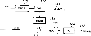
图7A所示举例,其中级数是两个和矢量量化是多级VQ。到第2级的输入是第1级从来自L2,g2和g1产生的较高精度的音调余项中减去的译码结果,即第1级MDCT电路113的输出是通过VQ电路114进行矢量量化,以便确定代表矢量或反量化输出中由逆MDCT电路113a进行逆MDCT的那个。结果输出被送到减法器128’,用于从第2级余项中减去(图1的逆音调滤波器122的输出)。减法器128’的输出被送到MDCT电路123’和结果的MDCT输出通过VQ电路124进行量化。这种结构类似于图7B的等效配置,其中MDCT没有行,图1使用了图7B的配置。An example is shown in Fig. 7A, where the number of stages is two and the vector quantization is multi-stage VQ. The input to the second stage is the decoding result of the first stage subtracted from the higher precision pitch remainder generated by L2 , g2 and g1 , that is, the output of the first
如果利用MDCT系数的索引IdxVq1和IdxVq2由图2所示译码器进行译码,则索引IdxVq1和IdxVq2的逆VQ的结果的和是逆MDCT和重叠加。随后进行音调合成和LPC合成以产生再现声音。当然,在音调合成期间音调延迟和音调增益更新频率是两倍于单级配置。这样,在本发明中,音调合成滤波器被驱动使其改变超过每次80采样。If decoded by the decoder shown in Figure 2 using indices IdxVq 1 and IdxVq 2 of the MDCT coefficients, the sum of the results of the inverse VQ of the indices IdxVq 1 and IdxVq 2 is the inverse MDCT and overlap-add. Tone synthesis and LPC synthesis are then performed to generate reproduced sound. Of course, the pitch delay and pitch gain update frequency during pitch synthesis is twice that of a single stage configuration. Thus, in the present invention, the pitch synthesis filter is driven to change over every 80 samples.
现在说明图2的译码器的后滤波器216,226。The post filters 216, 226 of the decoder of Fig. 2 will now be described.
该后滤波器通过音调加重,高范围加重和频谱加重滤波器的级联连接实现后滤波特片p(Z)。
在以上等式中,g1和L是通过音调预测确定的音调增益和音调延迟,而υ是指明音调加重强度的参数,例如为0.5。另外,υb是指明高范围加重的参数,例如υb=0.4,而υn和υd是指明频谱加重强度的参数,例如,υn=0.5,υd=0.8。In the above equations, g 1 and L are pitch gain and pitch delay determined by pitch prediction, and υ is a parameter indicating pitch emphasis strength, eg, 0.5. In addition, υ b is a parameter indicating high-range emphasis, for example, υ b =0.4, and υ n and υ d are parameters indicating spectrum emphasis strength, for example, υ n =0.5, υ d =0.8.
增益校准在LPC合成滤波器的输出s(n)和具有如下这样的系数kadj的后滤波器的输出sp(n)上进行。
kadj(n)=(1-p)kadj(n-1)+pkadj k adj (n)=(1-p)k adj (n-1)+pk adj
为帧之间的平滑连接,,使用两个音调加重滤波器,和使用滤波的平滑衰落结果作为最终的输出。
说明图1中所编码器侧VQ电路124。The encoder-
该VQ电路124具有两个不同类的码本,用于对应输入信号转换和选择的语音和音乐的。如果用于音乐声音信号的量化的量化器的配置是固定的,那么由量化器占有的码本随着在作为在学习期间使用的语音和音乐声音的特性而变得最佳。这样,如果语音和音乐声音被一起学习,和如果这两个在性质上有实质不同,则该作为学习的码本具有两个的平均性质,作为其中结果的性能或平均S/N值可以被假设在量化器仅用一个码本成形的情况下没有提高。The
这样,在本实施例中,利用用于具有不同特性的若干信号的学习数据准备的代码容量被转换用于改进量化器性能。Thus, in the present embodiment, the code capacity prepared with learning data for several signals with different characteristics is converted for improving quantizer performance.
图9示出了具有这样两类码本CBA,CBB的矢量量化器的结构图。Fig. 9 shows a structural diagram of a vector quantizer with such two types of codebooks CBA , CBB .
参考图9,提供给输入端501的输入信号被送到矢量量化器511,512。这些矢量量化器511,512占有码本CBA,CBB。矢量量化器511,512的代表矢量或去量化输出被分别送到减法器513,514,在这里与原始输入信号的差被加以确定以产生将被送到比较器515的误差分量。比较器515比较误差分量和通过转换开关516选择该矢量量化器511,512的量化输出中较小的一个索引,这选择的索引被送到输出端502。Referring to FIG. 9, an input signal supplied to an
转换开关516的转换周期要选得大于每个矢量量化器511,512的周期或量化单元时间。例如,如果量化单元是通过划分帧为8个所获得的子帧,则转换开关516的转换超过该帧的基本单位。The switching cycle of the
假设仅分别具有学习的语音和音乐声音的码本CBA,CBB是相同的尺寸N和维M的相同数。还可以假设,当由帧的L数据组成的L组数据X用子帧长度M(=L/n)进行矢量量化时,如果使用码本CBA,CBB,则随着量化的失真分别是EA(k)和EB(k)。如果索引i和j被选定,那么这些失真EA(k)和EB(k)由下式表示:Assuming that there are only codebooks CB A of learned speech and music sounds respectively, CB B is the same number of the same size N and dimension M. It can also be assumed that when the L group data X composed of the L data of the frame is vector quantized with the subframe length M (=L/n), if the codebooks CB A and CB B are used, the distortions along with the quantization are respectively E A (k) and E B (k). If indices i and j are chosen, then these distortions E A (k) and E B (k) are given by:
EA(k)=‖Wk(X-CAi)‖E A (k)=‖W k (XC Ai )‖
EB(k)=‖Wk(X-CBi)‖这里Wk是在子帧k处的加权矩阵,和CAj,CBj分别表示与码本CBA,CBB的索引i和j相关联的代表矢量。E B (k)=‖W k (XC Bi )‖ where W k is the weighting matrix at subframe k, and C Aj , C Bj respectively represent the indices i and j associated with the codebook CB A , CB B A representative vector of .
作为这样获得的两个失真,极适于给定帧的码本由在该帧中的失真的和所使用。下述两种方法可用于这样的选择。As the two distortions thus obtained, a codebook well suited for a given frame is used by the sum of the distortions in that frame. The following two methods can be used for such selection.
第一种方法是仅使用码本CBA,CBB去进行量化,以确定在帧∑kEA(k)和∑kEB(k)中的失真的和,并使用码本CBA或CBB中能对整个帧给出较小失真的一个。The first method is to use only codebooks CB A , CB B for quantization to determine the sum of distortions in frames ∑ k E A (k) and ∑ k E B (k), and use codebooks CB A or The one of CB B that gives less distortion to the entire frame.
图10示出用于实施第一种方法的配置,在该配置中,对应于图9所示的那些部分或成分由相同序号并对应于帧k用例如a、b,…的下标字母注明。对于码本CBA来说,该对于在失真基础上给定子帧的减法器513a,513b,…513n的输出的帧的和在加法器517确定。对于码本CBB来说,该对于在失真基础上的子帧的帧的和在加法器518确定。这些和通过比较器515相互比较以获得控制信号或选择信号以便在终端503处进行码本转换。Figure 10 shows an arrangement for implementing the first method, in which parts or components corresponding to those shown in Figure 9 are denoted by the same serial numbers and corresponding to frame k with subscript letters such as a, b, . . . bright. For codebook CBA , the frame sum of the outputs of the subtractors 513a, 513b, . . . 513n for a given subframe on a distortion basis is determined in the
第二种方法是对每个子帧的失真EA(k)和EB(k)进行比较并估计用于在帧中的子帧总体的比较结果,以用于转换码本的选择。The second method is to compare the distortions E A (k) and E B (k) of each subframe and estimate the comparison result for the population of subframes in the frame for the selection of the switching codebook.
在图11中示出了用于实现第二种方法的配置。在该配置中,用于在比较基础上子帧的比较器516的输出被送到判断逻辑519,用于通过多数判定给出判定结果,以用于在终端503处产生1位码本转换选择村志信号。A configuration for realizing the second method is shown in FIG. 11 . In this configuration, the output of the
该选择标志信号作为上述的S/M(语音/音乐)模式数据被加以传输。The selection flag signal is transmitted as the above-mentioned S/M (Speech/Music) mode data.
在该方法中,不同特性的若干信号能利用单一量化器进行有效量化。In this method, several signals of different characteristics can be effectively quantized using a single quantizer.
现在说明图1的通过FFT单元161的频率转换操作,频率移位电路162,和FFT电路163。The frequency conversion operation by the
频率转换处理包括,在输入信号中至少提取一个波段的波段提取步骤,将至少一个提取的波段信号变换为频率域信号的正交变换步骤,在频率域上将正交变换的信号移位到另一位置或波段的移位步骤,和在频率域上通过逆正交变换将移位的信号转换成时间域信号的逆正交变换步骤。The frequency conversion processing includes a band extraction step of extracting at least one band in the input signal, an orthogonal transform step of transforming at least one extracted band signal into a frequency domain signal, and shifting the orthogonally transformed signal to another frequency domain signal. A position or band shifting step, and an inverse orthogonal transform step converting the shifted signal into a time domain signal by inverse orthogonal transform in the frequency domain.
图12示出用于上述频率转换的更详细的结构。在图12中对应于图1的部分或成分由相同数字说明。在图12中具有0至8kHz成分和16kHz采样频率的宽范围语言信号被提供到输入端101。从输入端101来的宽波段语音信号中的,例如0至3.8kHz的波段,通过低通滤波器102被分离作为低范围信号,和通过减法器151从原始宽波段信号中减去低范围侧信号获得的剩余频率成分被分离出作为高频成分。低范围和高范围信号被分别处理。Fig. 12 shows a more detailed structure for the above frequency conversion. Parts or components in FIG. 12 corresponding to those in FIG. 1 are denoted by the same numerals. In FIG. 12 a wide-range speech signal having a 0 to 8 kHz component and a sampling frequency of 16 kHz is supplied to the
通过LPE 102之后留下的高范围侧信号具从3.5kHz至8kHz范围的4.5kHz的频率宽度。用下采样处理信号看,该频宽需要去减少到4kHz。在本实施例中,从7.5kHz至8kHz范围的0.5kHz的波段通过带通滤波器(BPF)107或LPF被截去。The high range side signal left after passing through the
然后,利用快速付利叶变换(FFT)将频畜转换到较低范围侧。然而,先于FFT,采样数在采样数等于2的幂,例如,如图13A所示的512采样的间隔处被划分。然而该采样被提前到每次80采样,以利于连续处理。Then, the frequency is converted to the lower range side using Fast Fourier Transform (FFT). However, prior to the FFT, the number of samples is divided at intervals where the number of samples is equal to a power of 2, eg, 512 samples as shown in FIG. 13A. However the sampling is advanced by 80 samples each to facilitate continuous processing.
然后通过Hamming窗口电路109提供320采样长度的Hamming窗口。被选择的320的采样数是4倍于80,该80的数是在帧划分的时间处预先采样的数。这使得4个波形稍后被加到在通过如图13B所示的重叠和加的帧合成时间处的重叠中。Then a Hamming window with a length of 320 samples is provided by the Hamming window circuit 109 . The selected number of samples of 320 is 4 times the number of 80 which is the number of samples pre-sampled at the time of frame division. This causes the 4 waveforms to be added later in the overlap at frame synthesis time by overlapping and adding as shown in Figure 13B.
该512采样数据然后通过FFT电路161进行FFT,以便转换成频率域数据。The 512 sampled data is then FFTed by the
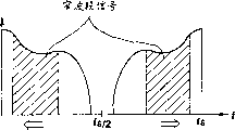
该频率域数据然后通过频率移位电路162被移位到频率轴上的另一位置或另一范围。较低采样频率的原理是,通过在频率轴上移位将图14A阴影所示高范围侧信号移位到图14B中指明的低范围侧并对如图14C所示的信号进行下采样。作为从图14A至图14B的在频率轴上移位时间处的中心与fs/z相混淆的频率成分在相反的方向上移位。这使得,如果子波段的范围低于fs/2n的话,该采样频率将被降低到fs/n。The frequency domain data is then shifted to another position or range on the frequency axis by the
频率移位电路162足以将图15阴影所示的高范围侧频率域数据移位到频率轴上的低范围侧位置或波段。特别是,在FFT512时间域数据上获得的512频率域数据被加以处理。这样,127数据,即第113至第239数据被分别移位到第1到第127位置或波段,而127数据,即第273至第399数据被分别移位到第395至第511位置或波段。在此时,属于监界的第112频率域数据没有被移位到第0位置或波段。理由是,频率域信号的第0个数据是dc成分和没有相位成分,使得该位置的数据应是一实数,这样,通常是复数的该频率分量不会被引入这个位置。还有,表示fs/z的通常为N/第2数据的第256数据也被无效和不被使用。那就是,0至4kHz范围应更正确的表示为0<f<4kHz。The
移位的数据通过逆FFT电路163进行逆FFT,将频率域数据恢复成时间域数据。该给出的时间域数据每次512采样。该在时间域信号基础上的512采样通过如图13B所示用于对重叠部分求和的重叠和加电路166重量叠为每次80采样。The shifted data is subjected to inverse FFT by the
通过重叠和加电路166获得的信号由16kHz采样限制为0至4kHz并由此通过下采样电路164进行下采样。这就通过用8kHz采的样的频率移位给出了0至4kHz的信号。该信号在输出端169取出并送到LPC分解量化单元130还送到图1所示的LPC逆滤波器171。The signal obtained by the overlap-and-add circuit 166 is limited by 16 kHz sampling to 0 to 4 kHz and thus down-sampled by the down-
通过图16所示的配置实现在译码器侧的译码操作。The decoding operation on the decoder side is realized by the configuration shown in FIG. 16 .
图16的配置对应于图2中上采样电路233的配置下游,和因此相应的部分由相同数字注明。虽然已由图2的上采样预先进行了FFT处理,随后由图16的实施例中的上采样再进行FFT处理。The configuration of FIG. 16 corresponds to the configuration downstream of the up-
在图16中,通过8kHz采样移位到0至4kHz的高范围侧信号,例如图2的高范围侧LPC合成滤波器232的输出信号被送到图16的端部241。In FIG. 16 , the high-range side signal shifted to 0 to 4 kHz by 8 kHz sampling, for example, the output signal of the high-range side
通过帧划分电路242将信号分成具有256采样的帧长度信号,并且由于如在编码器侧的帧划分的相同理由,还具有80采样的前置距离。然而,因为采样频率被二等分,该采样数也被二等分。来自帧划分电路242的信号通过Hamming窗口电路243用一Hamming窗口160采样长度相乘,该长度如同用于编码器侧的相同方法获得的长度相同(采样数无论如何是一半)。The signal is divided by the
结果信号通过FFT电路234用256采样长度进行FFT,用于将信号从时间轴转换为频率轴。接着,上采样电路244通过如图15B所示的零塞入(zero-stuffing)提供来自216采样的帧长度的512采样帧长度。这相应于从图14C转换到图14B。频率移位电路235然后将频率域数据移位到频率轴上的另一位置或波段,以用于+3.5kHz的频率移位。这相应于从图14B转换到图14A。The resulting signal is FFTed by the
结果的频率域信号通过逆FFT电路236进行逆FFT,以便恢复时间域信号。来自逆FFT电路236的信号范围从3.5kHz至7.5kHz并具有16kHz采样。The resulting frequency domain signal is subjected to an inverse FFT by an
接着,重叠和加电路237对每个512采样帧进行重叠加该每次80采样的时间域信号,以便恢复到连续的时间域信号。结果的高范围侧信号通过加法器228与低范围侧信号求合,和该结果的和信号在输出端229输出。Next, the overlap and add
对于,频率转换特定数字或值不限于上述实施例给定的那些。还有,波段数不限于1个。For, frequency conversion specific numbers or values are not limited to those given in the above embodiments. Also, the number of bands is not limited to one.
例如,如果窄波段信号的300kHz至3.4kHz和宽波段信号的0至7kHz通过如图17所示的16kHz采样产生,则0至300Hz的低范围信号没有被包含在窄波段中。该3.4kHz至7kHz的高范围侧被移位到300Hz至3.9kHz的范围,以便与低范围侧相接,该结果信号范围从0至3.9kHz,以便使得采样频率fs可以被二等分,即可以是8kHz。For example, if 300kHz to 3.4kHz of the narrowband signal and 0 to 7kHz of the wideband signal are generated by 16kHz sampling as shown in FIG. 17, the low range signal of 0 to 300Hz is not included in the narrowband. The 3.4kHz to 7kHz high range side is shifted to the 300Hz to 3.9kHz range to meet the low range side, the resulting signal ranges from 0 to 3.9kHz so that the sampling frequency fs can be halved, i.e. It can be 8kHz.
在更一般的限度内,如果宽波段信号用在该宽波段信号中包含的窄波段信号相乘,则窄波段信号被从宽波段信号中减去,和该在剩余信号中的高范围成分被移位到低范围侧,以用于低采样速率。In more general limits, if a wideband signal is multiplied by a narrowband signal contained in the wideband signal, the narrowband signal is subtracted from the wideband signal, and the high-range content in the remaining signal is Shifted to the low range side for use with low sample rates.
在此方法中,任意频率的子波段可以其它任意频率中产生并用在给定应用的任意范畴内的频率宽度的两倍的采样频率与灵活地应付给定的应用。In this approach, sub-bands of any frequency can be generated in any other frequency and used at a sampling frequency twice the frequency width within any range of a given application with the flexibility to address a given application.
如果量化误差由于低位率而变得较大,混淆的噪声通常产生在具有QMF使用的波段划分频率附近。这样混淆的噪声能用目前频率转换的方法分开。If the quantization error becomes large due to low bit rate, aliasing noise is usually generated near the band division frequency with QMF usage. Such aliasing noise can be separated by current frequency conversion methods.
本发明不限于上述实施例,例如,图1的语音编码器的配置图2的语音译码器的配置,由硬件表示,也可以通过利用数字信号处理器(DSP)的软件程序实现。还有,数据的若干帧可以集中并由代替矢量量化的矩阵量化加以量化。另外,根据本发明的编码和译码方法不限于上述特殊配置。本发明还可提供给各种应用,例如音调或速度转换,装配有计算机的语音合成或噪声抑制,并不局限于传送或记录/再现。The present invention is not limited to the above-mentioned embodiments, for example, the configuration of the speech coder of FIG. 1 and the configuration of the speech decoder of FIG. Also, several frames of data can be collected and quantized by matrix quantization instead of vector quantization. In addition, encoding and decoding methods according to the present invention are not limited to the above-mentioned specific configurations. The present invention can also be applied to various applications such as pitch or speed conversion, computer-equipped speech synthesis or noise suppression, and is not limited to transmission or recording/reproduction.
上述信号编码器和译码器可用于,例如,如图18和19所示的便携通讯终端或便携电话中的语音代码。The signal encoder and decoder described above can be used, for example, for speech codes in a portable communication terminal or a portable telephone as shown in FIGS. 18 and 19 .
图18是利用例如图1和图3所示构成的语音编码单元160的便携终端的发送器。通过图18的话筒661收集的语音信号由放大器662放大并由A/D转换器663转换成数字信号,该数字信号送到语音编码单元660。该语音编码单元660的构成如图1和3所示。送到编码单元660的输入端101的数字信号来自A/D转换器663。语音编码单元660执行如图1和3所说明的那样的编码。图1和3的输出端的输出信号作为语音编码单元660的输出信号被送到传输路径编码单元664,在这里进行信道译码和结果的输出信号被送到调制电路665并被解调,以便经由D/A转换器666和RF放大器667送到天线668。FIG. 18 is a transmitter of a portable terminal using
图19是利用如图2所示构成的语音译码单元760的便携终端的接收侧的配置。通过图19的天线761接收的语音信号由RF放大器762放大并经由A/D转换器763送到解调电路764,以便使该解调信号被送到传输路径译码单元765。解调电路764的输出信号被送到如图2所示构成的译码单元760。执行如联系图2所说明那样的信号译码。图2的输出端201的输出信号作为语音译码单元760的信号被送到D/A转换器766。来自D/A转换器766的模拟语音信号经由放大器767送到扬声器768。FIG. 19 is a configuration of the receiving side of the portable terminal using the
Claims (7)
Applications Claiming Priority (4)
| Application Number | Priority Date | Filing Date | Title |
|---|---|---|---|
| JP302199/95 | 1995-10-26 | ||
| JP302130/95 | 1995-10-26 | ||
| JP7302130A JPH09127986A (en) | 1995-10-26 | 1995-10-26 | Multiplexing method for coded signal and signal encoder |
| JP7302199A JPH09127987A (en) | 1995-10-26 | 1995-10-26 | Signal coding method and device therefor |
Publications (2)
| Publication Number | Publication Date |
|---|---|
| CN1154013A CN1154013A (en) | 1997-07-09 |
| CN1096148C true CN1096148C (en) | 2002-12-11 |
Family
ID=26562996
Family Applications (1)
| Application Number | Title | Priority Date | Filing Date |
|---|---|---|---|
| CN96121964A Expired - Fee Related CN1096148C (en) | 1995-10-26 | 1996-10-26 | Signal encoding method and apparatus |
Country Status (8)
| Country | Link |
|---|---|
| US (1) | US5819212A (en) |
| EP (2) | EP1262956B1 (en) |
| KR (1) | KR970024629A (en) |
| CN (1) | CN1096148C (en) |
| AU (1) | AU725251B2 (en) |
| BR (1) | BR9605251A (en) |
| DE (2) | DE69631728T2 (en) |
| TW (1) | TW321810B (en) |
Families Citing this family (81)
| Publication number | Priority date | Publication date | Assignee | Title |
|---|---|---|---|---|
| WO1997015046A1 (en) * | 1995-10-20 | 1997-04-24 | America Online, Inc. | Repetitive sound compression system |
| DE19613643A1 (en) * | 1996-04-04 | 1997-10-09 | Fraunhofer Ges Forschung | Method for coding an audio signal digitized with a low sampling rate |
| US6904404B1 (en) * | 1996-07-01 | 2005-06-07 | Matsushita Electric Industrial Co., Ltd. | Multistage inverse quantization having the plurality of frequency bands |
| JPH10105195A (en) * | 1996-09-27 | 1998-04-24 | Sony Corp | Pitch detection method, speech signal encoding method and apparatus |
| FI114248B (en) * | 1997-03-14 | 2004-09-15 | Nokia Corp | Method and apparatus for audio coding and audio decoding |
| CA2233896C (en) * | 1997-04-09 | 2002-11-19 | Kazunori Ozawa | Signal coding system |
| JP3235526B2 (en) * | 1997-08-08 | 2001-12-04 | 日本電気株式会社 | Audio compression / decompression method and apparatus |
| JP3279228B2 (en) * | 1997-08-09 | 2002-04-30 | 日本電気株式会社 | Encoded speech decoding device |
| US6889185B1 (en) * | 1997-08-28 | 2005-05-03 | Texas Instruments Incorporated | Quantization of linear prediction coefficients using perceptual weighting |
| JP3765171B2 (en) * | 1997-10-07 | 2006-04-12 | ヤマハ株式会社 | Speech encoding / decoding system |
| JP3199020B2 (en) * | 1998-02-27 | 2001-08-13 | 日本電気株式会社 | Audio music signal encoding device and decoding device |
| KR100304092B1 (en) * | 1998-03-11 | 2001-09-26 | 마츠시타 덴끼 산교 가부시키가이샤 | Audio signal coding apparatus, audio signal decoding apparatus, and audio signal coding and decoding apparatus |
| AU3372199A (en) * | 1998-03-30 | 1999-10-18 | Voxware, Inc. | Low-complexity, low-delay, scalable and embedded speech and audio coding with adaptive frame loss concealment |
| EP0957579A1 (en) * | 1998-05-15 | 1999-11-17 | Deutsche Thomson-Brandt Gmbh | Method and apparatus for sampling-rate conversion of audio signals |
| JP3541680B2 (en) * | 1998-06-15 | 2004-07-14 | 日本電気株式会社 | Audio music signal encoding device and decoding device |
| SE521225C2 (en) | 1998-09-16 | 2003-10-14 | Ericsson Telefon Ab L M | Method and apparatus for CELP encoding / decoding |
| US6266643B1 (en) | 1999-03-03 | 2001-07-24 | Kenneth Canfield | Speeding up audio without changing pitch by comparing dominant frequencies |
| JP2000330599A (en) * | 1999-05-21 | 2000-11-30 | Sony Corp | Signal processing method and apparatus, and information providing medium |
| FI116992B (en) * | 1999-07-05 | 2006-04-28 | Nokia Corp | Methods, systems, and devices for enhancing audio coding and transmission |
| JP3784583B2 (en) * | 1999-08-13 | 2006-06-14 | 沖電気工業株式会社 | Audio storage device |
| US7315815B1 (en) | 1999-09-22 | 2008-01-01 | Microsoft Corporation | LPC-harmonic vocoder with superframe structure |
| CA2310769C (en) * | 1999-10-27 | 2013-05-28 | Nielsen Media Research, Inc. | Audio signature extraction and correlation |
| WO2001059603A1 (en) * | 2000-02-09 | 2001-08-16 | Cheng T C | Fast method for the forward and inverse mdct in audio coding |
| US6606591B1 (en) * | 2000-04-13 | 2003-08-12 | Conexant Systems, Inc. | Speech coding employing hybrid linear prediction coding |
| EP1279167B1 (en) * | 2000-04-24 | 2007-05-30 | QUALCOMM Incorporated | Method and apparatus for predictively quantizing voiced speech |
| KR100378796B1 (en) * | 2001-04-03 | 2003-04-03 | 엘지전자 주식회사 | Digital audio encoder and decoding method |
| WO2002091202A1 (en) * | 2001-05-04 | 2002-11-14 | Globespan Virata Incorporated | System and method for distributed processing of packet data containing audio information |
| US20030035384A1 (en) * | 2001-08-16 | 2003-02-20 | Globespan Virata, Incorporated | Apparatus and method for concealing the loss of audio samples |
| US7353168B2 (en) * | 2001-10-03 | 2008-04-01 | Broadcom Corporation | Method and apparatus to eliminate discontinuities in adaptively filtered signals |
| US7706402B2 (en) * | 2002-05-06 | 2010-04-27 | Ikanos Communications, Inc. | System and method for distributed processing of packet data containing audio information |
| KR100462611B1 (en) * | 2002-06-27 | 2004-12-20 | 삼성전자주식회사 | Audio coding method with harmonic extraction and apparatus thereof. |
| KR100516678B1 (en) * | 2003-07-05 | 2005-09-22 | 삼성전자주식회사 | Device and method for detecting pitch of voice signal in voice codec |
| CN1839426A (en) * | 2003-09-17 | 2006-09-27 | 北京阜国数字技术有限公司 | Audio codec method and device for multi-resolution vector quantization |
| KR20060131793A (en) * | 2003-12-26 | 2006-12-20 | 마츠시타 덴끼 산교 가부시키가이샤 | Speech and Music Coding Device and Speech and Music Coding Method |
| US7668712B2 (en) * | 2004-03-31 | 2010-02-23 | Microsoft Corporation | Audio encoding and decoding with intra frames and adaptive forward error correction |
| RU2337478C2 (en) * | 2004-03-31 | 2008-10-27 | Интел Корпорейшн | Decoding of highly excessive code with parity check, using multithreshold message transfer |
| WO2005096509A1 (en) * | 2004-03-31 | 2005-10-13 | Intel Corporation | Multi-threshold message passing decoding of low-density parity check codes |
| US8209579B2 (en) * | 2004-03-31 | 2012-06-26 | Intel Corporation | Generalized multi-threshold decoder for low-density parity check codes |
| ATE406652T1 (en) * | 2004-09-06 | 2008-09-15 | Matsushita Electric Industrial Co Ltd | SCALABLE CODING DEVICE AND SCALABLE CODING METHOD |
| EP1840874B1 (en) * | 2005-01-11 | 2019-04-10 | NEC Corporation | Audio encoding device, audio encoding method, and audio encoding program |
| JP4800645B2 (en) * | 2005-03-18 | 2011-10-26 | カシオ計算機株式会社 | Speech coding apparatus and speech coding method |
| US7707034B2 (en) * | 2005-05-31 | 2010-04-27 | Microsoft Corporation | Audio codec post-filter |
| US7831421B2 (en) * | 2005-05-31 | 2010-11-09 | Microsoft Corporation | Robust decoder |
| US7177804B2 (en) * | 2005-05-31 | 2007-02-13 | Microsoft Corporation | Sub-band voice codec with multi-stage codebooks and redundant coding |
| US7974837B2 (en) * | 2005-06-23 | 2011-07-05 | Panasonic Corporation | Audio encoding apparatus, audio decoding apparatus, and audio encoded information transmitting apparatus |
| KR101171098B1 (en) * | 2005-07-22 | 2012-08-20 | 삼성전자주식회사 | Scalable speech coding/decoding methods and apparatus using mixed structure |
| US8281210B1 (en) * | 2006-07-07 | 2012-10-02 | Aquantia Corporation | Optimized correction factor for low-power min-sum low density parity check decoder (LDPC) |
| US8239190B2 (en) * | 2006-08-22 | 2012-08-07 | Qualcomm Incorporated | Time-warping frames of wideband vocoder |
| JP4827661B2 (en) * | 2006-08-30 | 2011-11-30 | 富士通株式会社 | Signal processing method and apparatus |
| RU2464650C2 (en) * | 2006-12-13 | 2012-10-20 | Панасоник Корпорэйшн | Apparatus and method for encoding, apparatus and method for decoding |
| KR101412255B1 (en) * | 2006-12-13 | 2014-08-14 | 파나소닉 인텔렉츄얼 프로퍼티 코포레이션 오브 아메리카 | Encoding device, decoding device, and method therof |
| MX2009009229A (en) * | 2007-03-02 | 2009-09-08 | Panasonic Corp | Encoding device and encoding method. |
| KR101403340B1 (en) * | 2007-08-02 | 2014-06-09 | 삼성전자주식회사 | Method and apparatus for transcoding |
| US8352249B2 (en) * | 2007-11-01 | 2013-01-08 | Panasonic Corporation | Encoding device, decoding device, and method thereof |
| US8631060B2 (en) * | 2007-12-13 | 2014-01-14 | Qualcomm Incorporated | Fast algorithms for computation of 5-point DCT-II, DCT-IV, and DST-IV, and architectures |
| ATE518224T1 (en) | 2008-01-04 | 2011-08-15 | Dolby Int Ab | AUDIO ENCODERS AND DECODERS |
| JP2011518345A (en) * | 2008-03-14 | 2011-06-23 | ドルビー・ラボラトリーズ・ライセンシング・コーポレーション | Multi-mode coding of speech-like and non-speech-like signals |
| KR20090122143A (en) * | 2008-05-23 | 2009-11-26 | 엘지전자 주식회사 | Audio signal processing method and apparatus |
| NO2313887T3 (en) * | 2008-07-10 | 2018-02-10 | ||
| WO2010044593A2 (en) | 2008-10-13 | 2010-04-22 | 한국전자통신연구원 | Lpc residual signal encoding/decoding apparatus of modified discrete cosine transform (mdct)-based unified voice/audio encoding device |
| KR101649376B1 (en) | 2008-10-13 | 2016-08-31 | 한국전자통신연구원 | Encoding and decoding apparatus for linear predictive coder residual signal of modified discrete cosine transform based unified speech and audio coding |
| FR2938688A1 (en) * | 2008-11-18 | 2010-05-21 | France Telecom | ENCODING WITH NOISE FORMING IN A HIERARCHICAL ENCODER |
| KR20110001130A (en) * | 2009-06-29 | 2011-01-06 | 삼성전자주식회사 | Audio signal encoding and decoding apparatus using weighted linear prediction transformation and method thereof |
| US8428959B2 (en) * | 2010-01-29 | 2013-04-23 | Polycom, Inc. | Audio packet loss concealment by transform interpolation |
| JP5651980B2 (en) * | 2010-03-31 | 2015-01-14 | ソニー株式会社 | Decoding device, decoding method, and program |
| EP2555186A4 (en) * | 2010-03-31 | 2014-04-16 | Korea Electronics Telecomm | METHOD AND DEVICE FOR ENCODING, AND METHOD AND DEVICE FOR DECODING |
| ES2911893T3 (en) | 2010-04-13 | 2022-05-23 | Fraunhofer Ges Forschung | Audio encoder, audio decoder, and related methods for processing stereo audio signals using variable prediction direction |
| KR101696632B1 (en) | 2010-07-02 | 2017-01-16 | 돌비 인터네셔널 에이비 | Selective bass post filter |
| JP5749462B2 (en) * | 2010-08-13 | 2015-07-15 | 株式会社Nttドコモ | Audio decoding apparatus, audio decoding method, audio decoding program, audio encoding apparatus, audio encoding method, and audio encoding program |
| WO2012144128A1 (en) | 2011-04-20 | 2012-10-26 | パナソニック株式会社 | Voice/audio coding device, voice/audio decoding device, and methods thereof |
| WO2012169133A1 (en) | 2011-06-09 | 2012-12-13 | パナソニック株式会社 | Voice coding device, voice decoding device, voice coding method and voice decoding method |
| JP5801614B2 (en) * | 2011-06-09 | 2015-10-28 | キヤノン株式会社 | Image processing apparatus and image processing method |
| US9070361B2 (en) * | 2011-06-10 | 2015-06-30 | Google Technology Holdings LLC | Method and apparatus for encoding a wideband speech signal utilizing downmixing of a highband component |
| JP5839848B2 (en) | 2011-06-13 | 2016-01-06 | キヤノン株式会社 | Image processing apparatus and image processing method |
| KR101762204B1 (en) * | 2012-05-23 | 2017-07-27 | 니폰 덴신 덴와 가부시끼가이샤 | Encoding method, decoding method, encoder, decoder, program and recording medium |
| CN104282308B (en) * | 2013-07-04 | 2017-07-14 | 华为技术有限公司 | Vector Quantization Method and Device for Frequency Domain Envelope |
| KR101883767B1 (en) * | 2013-07-18 | 2018-07-31 | 니폰 덴신 덴와 가부시끼가이샤 | Linear prediction analysis device, method, program, and storage medium |
| US10146500B2 (en) * | 2016-08-31 | 2018-12-04 | Dts, Inc. | Transform-based audio codec and method with subband energy smoothing |
| WO2020032177A1 (en) * | 2018-08-10 | 2020-02-13 | ヤマハ株式会社 | Method and device for generating frequency component vector of time-series data |
| US11756530B2 (en) * | 2019-10-19 | 2023-09-12 | Google Llc | Self-supervised pitch estimation |
| CN110708126B (en) * | 2019-10-30 | 2021-07-06 | 中电科思仪科技股份有限公司 | A broadband integrated vector signal modulation device and method |
Citations (2)
| Publication number | Priority date | Publication date | Assignee | Title |
|---|---|---|---|---|
| US5371853A (en) * | 1991-10-28 | 1994-12-06 | University Of Maryland At College Park | Method and system for CELP speech coding and codebook for use therewith |
| US5444846A (en) * | 1981-07-15 | 1995-08-22 | Canon Kabushiki Kaisha | Image processing apparatus having diagnostic mode |
Family Cites Families (12)
| Publication number | Priority date | Publication date | Assignee | Title |
|---|---|---|---|---|
| US3750024A (en) * | 1971-06-16 | 1973-07-31 | Itt Corp Nutley | Narrow band digital speech communication system |
| CA1288182C (en) * | 1987-06-02 | 1991-08-27 | Mitsuhiro Azuma | Secret speech equipment |
| CN1011991B (en) * | 1988-08-29 | 1991-03-13 | 里特机械公司 | A heating method in textile machinery |
| JPH02272500A (en) * | 1989-04-13 | 1990-11-07 | Fujitsu Ltd | Code driving voice encoding system |
| IT1232084B (en) * | 1989-05-03 | 1992-01-23 | Cselt Centro Studi Lab Telecom | CODING SYSTEM FOR WIDE BAND AUDIO SIGNALS |
| JPH03117919A (en) * | 1989-09-30 | 1991-05-20 | Sony Corp | Digital signal encoding device |
| CA2010830C (en) * | 1990-02-23 | 1996-06-25 | Jean-Pierre Adoul | Dynamic codebook for efficient speech coding based on algebraic codes |
| DE9006717U1 (en) * | 1990-06-15 | 1991-10-10 | Philips Patentverwaltung GmbH, 22335 Hamburg | Answering machine for digital recording and playback of voice signals |
| CA2075156A1 (en) * | 1991-08-02 | 1993-02-03 | Kenzo Akagiri | Digital encoder with dynamic quantization bit allocation |
| JP3343965B2 (en) * | 1992-10-31 | 2002-11-11 | ソニー株式会社 | Voice encoding method and decoding method |
| JPH0787483A (en) * | 1993-09-17 | 1995-03-31 | Canon Inc | Image coding / decoding device, image coding device, and image decoding device |
| JP3046213B2 (en) * | 1995-02-02 | 2000-05-29 | 三菱電機株式会社 | Sub-band audio signal synthesizer |
-
1996
- 1996-10-21 TW TW085112854A patent/TW321810B/zh not_active IP Right Cessation
- 1996-10-23 AU AU70373/96A patent/AU725251B2/en not_active Ceased
- 1996-10-24 US US08/736,507 patent/US5819212A/en not_active Expired - Lifetime
- 1996-10-25 EP EP02017464A patent/EP1262956B1/en not_active Expired - Lifetime
- 1996-10-25 KR KR1019960048692A patent/KR970024629A/en not_active Ceased
- 1996-10-25 EP EP96307742A patent/EP0770985B1/en not_active Expired - Lifetime
- 1996-10-25 DE DE69631728T patent/DE69631728T2/en not_active Expired - Lifetime
- 1996-10-25 DE DE69634645T patent/DE69634645T2/en not_active Expired - Lifetime
- 1996-10-25 BR BR9605251A patent/BR9605251A/en active Search and Examination
- 1996-10-26 CN CN96121964A patent/CN1096148C/en not_active Expired - Fee Related
Patent Citations (2)
| Publication number | Priority date | Publication date | Assignee | Title |
|---|---|---|---|---|
| US5444846A (en) * | 1981-07-15 | 1995-08-22 | Canon Kabushiki Kaisha | Image processing apparatus having diagnostic mode |
| US5371853A (en) * | 1991-10-28 | 1994-12-06 | University Of Maryland At College Park | Method and system for CELP speech coding and codebook for use therewith |
Also Published As
| Publication number | Publication date |
|---|---|
| EP1262956A2 (en) | 2002-12-04 |
| AU725251B2 (en) | 2000-10-12 |
| US5819212A (en) | 1998-10-06 |
| DE69634645T2 (en) | 2006-03-02 |
| AU7037396A (en) | 1997-05-01 |
| CN1154013A (en) | 1997-07-09 |
| EP0770985A2 (en) | 1997-05-02 |
| EP0770985A3 (en) | 1998-10-07 |
| EP1262956B1 (en) | 2005-04-20 |
| KR970024629A (en) | 1997-05-30 |
| EP1262956A3 (en) | 2003-01-08 |
| BR9605251A (en) | 1998-07-21 |
| DE69634645D1 (en) | 2005-05-25 |
| TW321810B (en) | 1997-12-01 |
| DE69631728D1 (en) | 2004-04-08 |
| DE69631728T2 (en) | 2005-02-10 |
| EP0770985B1 (en) | 2004-03-03 |
Similar Documents
| Publication | Publication Date | Title |
|---|---|---|
| CN1096148C (en) | Signal encoding method and apparatus | |
| CN1264138C (en) | Method and device for duplicating speech signal, decoding speech, and synthesizing speech | |
| CN1172292C (en) | Method and apparatus for adaptive bandwidth tone searching in an encoded wideband signal | |
| CN1155725A (en) | Speech encoding method and apparatus | |
| CN1156872A (en) | Speech coding method and device | |
| CN1200403C (en) | Vector Quantization Device for Linear Predictive Coding Parameters | |
| CN1161751C (en) | Speech Analysis Method, Speech Coding Method and Device | |
| CN1202514C (en) | Method for encoding and decoding speech and its parameters, encoder, decoder | |
| CN1185620C (en) | Sound synthetizer and method, telephone device and program service medium | |
| CN1135527C (en) | Speech encoding method and device, input signal discrimination method, speech decoding method and device, and program providing medium | |
| CN1291375C (en) | Acoustic signal coding method and device, decoding method and device | |
| CN1689069A (en) | Sound encoding apparatus and sound encoding method | |
| CN1871501A (en) | Spectrum encoding device, spectrum decoding device, audio signal transmitting device, audio signal receiving device and method of use thereof | |
| CN1240978A (en) | Audio signal encoding device, decoding device and audio signal encoding-decoding device | |
| CN1145512A (en) | Method and apparatus for reproducing speech signals and method for transmitting same | |
| CN101048814A (en) | Encoding device, decoding device, encoding method, and decoding method | |
| CN1629937A (en) | Source coding enhancement using spectral-band replication | |
| CN1677493A (en) | Intensified audio-frequency coding-decoding device and method | |
| CN1910657A (en) | Audio signal encoding method, audio signal decoding method, transmitter, receiver, and wireless microphone system | |
| CN1849648A (en) | encoding device and decoding device | |
| CN1484824A (en) | Method and system for estimating an analog high band signal in a voice modem | |
| CN1547734A (en) | Audio signal encoding method and device, audio signal decoding method and device, program, and recording medium | |
| CN101057275A (en) | Vector conversion device and vector conversion method | |
| CN1677492A (en) | Intensified audio-frequency coding-decoding device and method | |
| CN1496556A (en) | Sound encoding device and method and sound decoding device and method |
Legal Events
| Date | Code | Title | Description |
|---|---|---|---|
| C06 | Publication | ||
| PB01 | Publication | ||
| C10 | Entry into substantive examination | ||
| SE01 | Entry into force of request for substantive examination | ||
| C14 | Grant of patent or utility model | ||
| GR01 | Patent grant | ||
| C17 | Cessation of patent right | ||
| CF01 | Termination of patent right due to non-payment of annual fee |
Granted publication date: 20021211 Termination date: 20131026 |