CN109660935B - A kind of interference localization method of base station side array antenna system - Google Patents
A kind of interference localization method of base station side array antenna system Download PDFInfo
- Publication number
- CN109660935B CN109660935B CN201811428477.4A CN201811428477A CN109660935B CN 109660935 B CN109660935 B CN 109660935B CN 201811428477 A CN201811428477 A CN 201811428477A CN 109660935 B CN109660935 B CN 109660935B
- Authority
- CN
- China
- Prior art keywords
- interference
- base station
- user
- power
- path loss
- Prior art date
- Legal status (The legal status is an assumption and is not a legal conclusion. Google has not performed a legal analysis and makes no representation as to the accuracy of the status listed.)
- Active
Links
- 238000000034 method Methods 0.000 title claims abstract description 25
- 230000004807 localization Effects 0.000 title 1
- 238000004364 calculation method Methods 0.000 claims description 6
- 238000012795 verification Methods 0.000 claims description 3
- 230000005540 biological transmission Effects 0.000 abstract description 6
- 238000004891 communication Methods 0.000 abstract description 6
- 238000007689 inspection Methods 0.000 abstract description 3
- 238000012360 testing method Methods 0.000 abstract description 2
- 238000010586 diagram Methods 0.000 description 4
- 238000011835 investigation Methods 0.000 description 3
- 238000005259 measurement Methods 0.000 description 3
- 230000009286 beneficial effect Effects 0.000 description 1
- 238000001514 detection method Methods 0.000 description 1
- 230000002452 interceptive effect Effects 0.000 description 1
- 238000013178 mathematical model Methods 0.000 description 1
- 238000012986 modification Methods 0.000 description 1
- 230000004048 modification Effects 0.000 description 1
- 238000012545 processing Methods 0.000 description 1
- 238000011160 research Methods 0.000 description 1
- 238000001228 spectrum Methods 0.000 description 1
Images


Classifications
-
- H—ELECTRICITY
- H04—ELECTRIC COMMUNICATION TECHNIQUE
- H04W—WIRELESS COMMUNICATION NETWORKS
- H04W4/00—Services specially adapted for wireless communication networks; Facilities therefor
- H04W4/02—Services making use of location information
-
- H—ELECTRICITY
- H04—ELECTRIC COMMUNICATION TECHNIQUE
- H04B—TRANSMISSION
- H04B17/00—Monitoring; Testing
- H04B17/30—Monitoring; Testing of propagation channels
- H04B17/309—Measuring or estimating channel quality parameters
- H04B17/318—Received signal strength
- H04B17/327—Received signal code power [RSCP]
-
- H—ELECTRICITY
- H04—ELECTRIC COMMUNICATION TECHNIQUE
- H04B—TRANSMISSION
- H04B17/00—Monitoring; Testing
- H04B17/30—Monitoring; Testing of propagation channels
- H04B17/309—Measuring or estimating channel quality parameters
- H04B17/345—Interference values
-
- H—ELECTRICITY
- H04—ELECTRIC COMMUNICATION TECHNIQUE
- H04W—WIRELESS COMMUNICATION NETWORKS
- H04W24/00—Supervisory, monitoring or testing arrangements
- H04W24/08—Testing, supervising or monitoring using real traffic
-
- H—ELECTRICITY
- H04—ELECTRIC COMMUNICATION TECHNIQUE
- H04W—WIRELESS COMMUNICATION NETWORKS
- H04W64/00—Locating users or terminals or network equipment for network management purposes, e.g. mobility management
-
- Y—GENERAL TAGGING OF NEW TECHNOLOGICAL DEVELOPMENTS; GENERAL TAGGING OF CROSS-SECTIONAL TECHNOLOGIES SPANNING OVER SEVERAL SECTIONS OF THE IPC; TECHNICAL SUBJECTS COVERED BY FORMER USPC CROSS-REFERENCE ART COLLECTIONS [XRACs] AND DIGESTS
- Y02—TECHNOLOGIES OR APPLICATIONS FOR MITIGATION OR ADAPTATION AGAINST CLIMATE CHANGE
- Y02D—CLIMATE CHANGE MITIGATION TECHNOLOGIES IN INFORMATION AND COMMUNICATION TECHNOLOGIES [ICT], I.E. INFORMATION AND COMMUNICATION TECHNOLOGIES AIMING AT THE REDUCTION OF THEIR OWN ENERGY USE
- Y02D30/00—Reducing energy consumption in communication networks
- Y02D30/70—Reducing energy consumption in communication networks in wireless communication networks
Landscapes
- Engineering & Computer Science (AREA)
- Computer Networks & Wireless Communication (AREA)
- Signal Processing (AREA)
- Quality & Reliability (AREA)
- Physics & Mathematics (AREA)
- Electromagnetism (AREA)
- Mobile Radio Communication Systems (AREA)
Abstract
本发明公开了一种基站侧阵列天线系统的干扰定位方法,通过定时关闭基站和用户的数据发送,并同时接收干扰信息,通过DOA方法确定基站侧干扰方向,用户将所接收到干扰功率上报基站,从而根据基站和用户接收干扰信息联合判断计算干扰位置区域及功率,该方法可有效定位干扰位置区域,并且不需要增加额外测试设备,无需进行人工排查,节约人力物力,并且可有效定位干扰位置区域和发射功率;该定位干扰位置的方法,算法复杂度低,适用于基站侧阵列天线的通信系统。
The invention discloses an interference positioning method for an array antenna system on the base station side. By regularly shutting down the data transmission of the base station and the user, and simultaneously receiving the interference information, the interference direction of the base station side is determined by the DOA method, and the user reports the received interference power to the base station. , so as to jointly judge and calculate the interference location area and power according to the interference information received by the base station and the user, this method can effectively locate the interference location area, and does not need to add additional testing equipment, does not need to perform manual inspection, saves manpower and material resources, and can effectively locate the interference location. Area and transmit power; the method for locating the interference position has low algorithm complexity and is suitable for the communication system of the array antenna on the base station side.
Description
技术领域technical field
本发明涉及通信领域,尤其涉及一种基站侧阵列天线系统的干扰定位方法。The present invention relates to the field of communications, and in particular, to a method for locating interference of a base station side array antenna system.
背景技术Background technique
无线信道的共享特性使得无线网络容易受到网内自干扰或者异系统干扰等威胁。为了有效地应对干扰攻击,国内外研究者从物理层通信模式、链路层调度策略、网络层路由算法和应用层服务质量调整等角度提出了包括信道级、链路级和网络级在内的干扰消除或规避方法。对比来看,如何有效地定位干扰源以便从源头上消除干扰威胁研究较少。目前,常用的干扰源定位方法为人工上站干扰排查法。此方法是通常使用定向天线(八木天线,对数周期天线,平板定向天线等)来测量信号方向,同时配备高性能的频谱检测装置对检测的信号波形状进行观察,一旦出现干扰信号持续时间较长的现象,测试人员将在测量地点转动天线并定向。通过在若干个地点使用定向天线测量干扰信号,可大致确定干扰源位置。人工排查方法存在以下不足,(1)测量步骤繁琐,效率低下;(2)共站址建设基站数目多,排查工程量大;(3)测量信号为时变信号,受偶然情况影响,结果存在误差。The sharing characteristics of wireless channels make wireless networks vulnerable to threats such as intra-network self-interference or inter-system interference. In order to effectively deal with jamming attacks, researchers at home and abroad have proposed methods including channel-level, link-level and network-level from the perspectives of physical layer communication mode, link layer scheduling strategy, network layer routing algorithm and application layer QoS adjustment. Interference cancellation or avoidance methods. In contrast, there is less research on how to effectively locate the interference source in order to eliminate the interference threat from the source. At present, the commonly used method for locating the interference source is the manual access to the station interference investigation method. This method usually uses a directional antenna (Yagi antenna, logarithmic period antenna, flat panel directional antenna, etc.) to measure the signal direction, and is equipped with a high-performance spectrum detection device to observe the shape of the detected signal wave. For a long phenomenon, the tester will turn the antenna and orient it at the measurement site. By measuring the interfering signal using directional antennas at several locations, the location of the source of the interference can be roughly determined. The manual inspection method has the following shortcomings: (1) the measurement steps are cumbersome and the efficiency is low; (2) the number of base stations constructed at the same site is large, and the inspection workload is large; (3) the measurement signal is a time-varying signal, which is affected by accidental circumstances, and the results exist error.
发明内容SUMMARY OF THE INVENTION
本发明的目的在于提供一种误差小、效率高的基站侧阵列天线系统的干扰定位方法。The purpose of the present invention is to provide a method for locating the interference of the base station side array antenna system with small error and high efficiency.
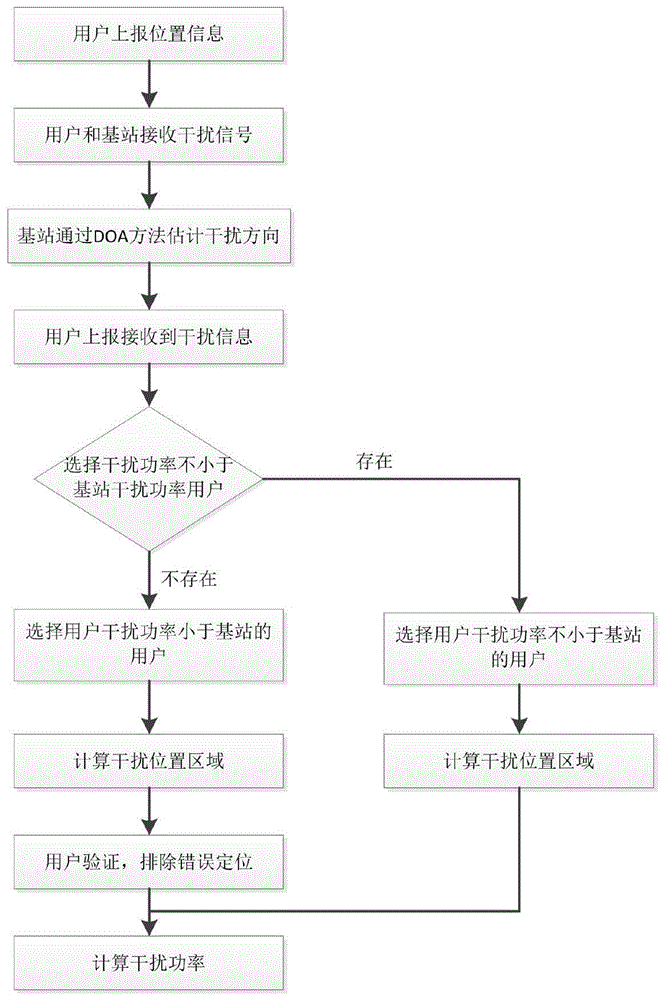
为实现上述目的,本发明提供如下技术方案:一种基站侧阵列天线系统的干扰定位方法,其特征在于,包括如下步骤:In order to achieve the above object, the present invention provides the following technical solutions: a method for locating interference for an array antenna system on the base station side, which is characterized in that it includes the following steps:
步骤1、用户上报位置信息;Step 1. The user reports location information;
步骤2、基站和用户定时停止信息发送,只接收干扰信息;
步骤3、基站通过DOA方法判断干扰信号方向;Step 3, the base station judges the direction of the interference signal by the DOA method;
步骤4、用户上报所接收的干扰的功率;Step 4, the user reports the received interference power;
步骤5、若存在干扰功率不大于基站干扰功率的用户,则随机选取一个此类用户,并进入步骤6,否则,随机选取干扰功率大于基站的用户,进入步骤7;Step 5. If there is a user whose interference power is not greater than that of the base station, select one such user at random, and proceed to step 6; otherwise, randomly select a user whose interference power is greater than that of the base station, and proceed to step 7;
步骤6、根据基站接收干扰功率、步骤5所选取用户干扰功率、路径损耗模型、基站估计干扰方向,联合计算并确定干扰位置,输出确定干扰位置区域,计算完成后进入步骤8;Step 6, according to the interference power received by the base station, the user interference power selected in step 5, the path loss model, and the estimated interference direction of the base station, jointly calculate and determine the interference location, output the determined interference location area, and enter
步骤7、所选取用户干扰功率大于基站干扰功率;Step 7. The selected user interference power is greater than the base station interference power;
步骤8、根据干扰位置、干扰接收功率及路径损耗模型,计算干扰发射功率。Step 8: Calculate the interference transmission power according to the interference position, the interference received power and the path loss model.
进一步的,所述步骤7还包括如下步骤:Further, the step 7 also includes the following steps:
7a、根据基站接收干扰功率、步骤5所选取用户干扰功率、路径损耗模型、基站估计干扰方向,联合计算干扰位置,此时干扰位置区域计算结果有两个;7a. Jointly calculate the interference position according to the interference power received by the base station, the user interference power selected in step 5, the path loss model, and the estimated interference direction of the base station. At this time, there are two calculation results of the interference position area;
7b、从未选取的用户中再选取一个用户,根据接收功率和路径损耗模型,对步骤7a所计算得到的两个干扰位置区域进行验证,输出确定干扰位置区域,若两区域验证均正确,则重新另外选取两个用户进行验证。7b. Select another user from the unselected users, verify the two interference location areas calculated in step 7a according to the received power and path loss model, and output the determined interference location area. If the verification of the two areas is correct, then Reselect two additional users to authenticate.
与现有技术相比,本发明的有益效果是:无需进行人工排查,节约人力物力,并且可有效定位干扰位置区域和发射功率;该定位干扰位置的方法,算法复杂度低,适用于基站侧阵列天线的通信系统。Compared with the prior art, the present invention has the following beneficial effects: no manual investigation is required, manpower and material resources are saved, and the interference location area and transmission power can be effectively located; the method for locating the interference location has low algorithm complexity and is suitable for the base station side Array antenna for communication systems.
附图说明Description of drawings
图1为干扰距用户较近情况下的示意图;Fig. 1 is a schematic diagram when the interference is close to the user;
图2为干扰距基站较近情况下的示意图;Fig. 2 is a schematic diagram when the interference is relatively close to the base station;
图3为图1表示的情形的模型图;Fig. 3 is a model diagram of the situation shown in Fig. 1;
图4位图2表示的情形的模型图;Figure 4 is a model diagram of the situation represented by Figure 2;
图5是本发明的流程示意图。FIG. 5 is a schematic flow chart of the present invention.
具体实施方式Detailed ways
下面将结合本发明实施例中的附图,对本发明实施例中的技术方案进行清楚、完整地描述,显然,所描述的实施例仅仅是本发明一部分实施例,而不是全部的实施例。基于本发明中的实施例,本领域普通技术人员在没有做出创造性劳动前提下所获得的所有其他实施例,都属于本发明保护的范围。The technical solutions in the embodiments of the present invention will be clearly and completely described below with reference to the accompanying drawings in the embodiments of the present invention. Obviously, the described embodiments are only a part of the embodiments of the present invention, but not all of the embodiments. Based on the embodiments of the present invention, all other embodiments obtained by those of ordinary skill in the art without creative efforts shall fall within the protection scope of the present invention.
参看图1-图5,本具体实施方式披露了一种基站侧阵列天线系统的干扰定位方法,干扰系统模型如图1、2所示,图1为干扰距用户较近情况,图2为干扰距基站较近情况。假设基站侧为阵列天线,基站和用户定时停止数据发送,并进行干扰接收。用户将接收到的干扰信息上报给基站,通过对所接收干扰进行处理,定位干扰。整个系统由模块101、模块102、模块103和模块104组成,其中模块101是阵列天线基站,主要作用接收干扰并估计干扰方向;模块102是用户终端,一般指用户收发数据的设备,如手机、笔记本等;模块103是干扰,即为本方案需定位部分;模块104是无线通信链路,主要作用是传输无线信号。图3、4分别为与图1和2对应的数学模型。Referring to Figures 1 to 5, this specific embodiment discloses a method for locating interference for an array antenna system on the base station side. The interference system model is shown in Figures 1 and 2. Figure 1 shows the situation where the interference is close to the user, and Figure 2 shows the interference Close to the base station. Assuming that the base station side is an array antenna, the base station and the user periodically stop data transmission and perform interference reception. The user reports the received interference information to the base station, and locates the interference by processing the received interference. The whole system consists of
如图5所示,为基站侧阵列天线系统干扰定位方法流程图,具体包括如下步骤:As shown in Figure 5, it is a flowchart of the method for locating the interference of the array antenna system on the base station side, which specifically includes the following steps:
步骤1、用户上报位置信息;Step 1. The user reports location information;
步骤2、基站和用户定时停止信息发送,只接收干扰信息,基站接收干扰功率为PB,用户m接收到干扰功率为Pm;
步骤3、基站通过DOA方法估计干扰信号方向,如图3、4中BI射线所示;Step 3. The base station estimates the direction of the interference signal through the DOA method, as shown in the BI rays in Figures 3 and 4;
步骤4、用户上报所接收干扰的功率;Step 4, the user reports the power of the received interference;
步骤5、若存在干扰功率不大于基站干扰功率的用户,即存在用户m,使得接收干扰功率Pm≤PB,则随机选取一个此类用户,并进入步骤6,否则,随机选取干扰功率大于基站的用户m,进入步骤7;Step 5. If there is a user whose interference power is not greater than the interference power of the base station, that is, there is a user m, such that the received interference power P m ≤ P B , then randomly select such a user, and enter step 6, otherwise, randomly select a user whose interference power is greater than or equal to P B . User m of the base station, go to step 7;
步骤6、以基站和用户所在平面建立坐标系,用户m所在位置为点Um,基站所在位置为点B,如图3所示。根据基站接收干扰功率PB、步骤5所选取用户m干扰功率Pm、路径损耗模型、基站估计干扰方向,联合计算并确定干扰位置,具体过程如下:Step 6: Establish a coordinate system based on the plane where the base station and the user are located. The location of the user m is the point U m , and the location of the base station is the point B, as shown in FIG. 3 . According to the received interference power P B of the base station, the interference power P m of the user m selected in step 5, the path loss model, and the estimated interference direction of the base station, jointly calculate and determine the interference position, and the specific process is as follows:
根据不同环境选择不同路径损耗模型,此处选择Hata-Okumura模型,则:Different path loss models are selected according to different environments, and the Hata-Okumura model is selected here, then:
PT-Pm=69.55+26.16lgf-13.82lght-α(hm)+(44.9-6.55lght)*lgdm (1)P T -P m =69.55+26.16lgf-13.82lght-α(hm)+(44.9-6.55lght)*lgd m (1)
PT-PB=69.55+26.16lgf-13.82lght-α(hB)+(44.9-6.55lght)*lgdB (2)P T -P B =69.55+26.16lgf-13.82lght-α(hB)+(44.9-6.55lght)*lgd B (2)
其中:PT为干扰发射功率;Wherein: P T is the interference transmit power;
f为干扰信号频率;f is the frequency of the interference signal;
ht为干扰天线有效高度(m);ht is the effective height of the interference antenna (m);
hm为用户天线有效高度(m);hm is the effective height of the user antenna (m);
dB为干扰与基站之间的距离(km); dB is the distance (km) between the interference and the base station;
α为接收天线高度因子;α is the receiving antenna height factor;
(1)式减(2)式整理得:Formula (1) minus formula (2) is sorted out:

分别将ht=30m和ht=200m带入上式,可得干扰高度在30到200m之间时用户到干扰距离与基站到干扰距离比λ得值,且:Taking ht=30m and ht=200m into the above equation respectively, the ratio λ between the user-to-interference distance and the base-station-to-interference distance can be obtained when the interference height is between 30 and 200m, and:

当λ=1时,根据数学知识可知,干扰位于用户和基站中垂线上,与射线BI交点即为干扰所在位置,此时可以唯一确定干扰位置;When λ=1, according to mathematical knowledge, the interference is located on the vertical line between the user and the base station, and the intersection with the ray BI is the location of the interference, and the interference location can be uniquely determined at this time;
当λ>1时,根据数学知识可知,到两定点距离比值恒定的点的轨迹为圆,轨迹圆位于右侧,如图3所示,两圆分别表示干扰高度在两极限值情况,干扰所在位置即为射线BI与两圆交点处之间得阴影部分区域,此时可以唯一确定干扰位置区域;When λ>1, according to mathematical knowledge, the trajectory to the point with a constant distance ratio between the two fixed points is a circle, and the trajectory circle is located on the right side, as shown in Figure 3, the two circles represent the interference heights at the two extreme values. The position is the shaded area between the ray BI and the intersection of the two circles, and the interference position area can be uniquely determined at this time;
计算完成后进入步骤8;After the calculation is completed, go to
步骤7、所选取用户干扰功率大于基站干扰功率,则需分下面两步进行Step 7. If the selected user interference power is greater than the base station interference power, the following two steps are required.
7a、以基站和用户所在平面建立坐标系,用户m所在位置为点Um,基站所在位置为点B,如图4所示。根据基站接收干扰功率、步骤5所选取用户干扰功率、路径损耗模型、基站估计干扰方向,联合计算干扰位置。7a. Establish a coordinate system based on the plane where the base station and the user are located. The location of the user m is the point U m , and the location of the base station is the point B, as shown in FIG. 4 . According to the received interference power of the base station, the user interference power selected in step 5, the path loss model, and the estimated interference direction of the base station, the interference position is jointly calculated.
此时与步骤6相同,根据路径损耗模型可得用户到干扰距离与基站到干扰距离比λ且:At this time, it is the same as step 6. According to the path loss model, the ratio λ between the user-to-interference distance and the base-station-to-interference distance can be obtained and:

7b、从未选取的用户中再选取一个用户n,根据接收功率和路径损耗模型,对步骤7a所计算得到的两个干扰位置区域进行验证,从而确定正确的干扰位置区域。若验证步骤7a两区域均正确,说明两用户关于基站干扰连线对称,需重新执行步骤7b;7b. Select another user n from the unselected users, and verify the two interference location areas calculated in step 7a according to the received power and path loss model, so as to determine the correct interference location area. If it is verified that the two areas in step 7a are correct, it means that the two users are symmetrical about the base station interference connection, and step 7b needs to be performed again;
步骤8、根据干扰位置、干扰接收功率及路径损耗模型,估计干扰发射功率。Step 8: Estimate the interference transmit power according to the interference position, the interference received power and the path loss model.
本发明可以通过系统自动进行定位或者人工操作,从而无需进行人工排查,节约人力物力,并且针对以基站侧为阵列天线的系统,可以有效的定位干扰位置区域和发射功率;利用基站接收干扰信息结合用户端接收的干扰信息,进行定位干扰位置,算法复杂度低,适用于基站侧阵列天线的通信系统,并且不需要额外的测试设备。The present invention can automatically perform positioning or manual operation through the system, thereby eliminating the need for manual investigation, saving manpower and material resources, and for the system with the base station side as the array antenna, it can effectively locate the interference location area and transmit power; use the base station to receive interference information combined with The interference information received by the user terminal is used to locate the interference position, and the algorithm complexity is low, which is suitable for the communication system of the array antenna on the base station side, and does not require additional testing equipment.
尽管参照前述实施例对本发明进行了详细的说明,对于本领域的技术人员来说,其依然可以对前述各实施例所记载的技术方案进行修改,或者对其中部分技术特征进行等同替换,凡在本发明的精神和原则之内,所作的任何修改、等同替换、改进等,均应包含在本发明的保护范围之内。Although the present invention has been described in detail with reference to the foregoing embodiments, for those skilled in the art, it is still possible to modify the technical solutions described in the foregoing embodiments, or to perform equivalent replacements for some of the technical features. Any modification, equivalent replacement, improvement, etc. made within the spirit and principle of the present invention shall be included within the protection scope of the present invention.
Claims (2)


Priority Applications (1)
| Application Number | Priority Date | Filing Date | Title |
|---|---|---|---|
| CN201811428477.4A CN109660935B (en) | 2018-11-27 | 2018-11-27 | A kind of interference localization method of base station side array antenna system |
Applications Claiming Priority (1)
| Application Number | Priority Date | Filing Date | Title |
|---|---|---|---|
| CN201811428477.4A CN109660935B (en) | 2018-11-27 | 2018-11-27 | A kind of interference localization method of base station side array antenna system |
Publications (2)
| Publication Number | Publication Date |
|---|---|
| CN109660935A CN109660935A (en) | 2019-04-19 |
| CN109660935B true CN109660935B (en) | 2020-12-18 |
Family
ID=66111634
Family Applications (1)
| Application Number | Title | Priority Date | Filing Date |
|---|---|---|---|
| CN201811428477.4A Active CN109660935B (en) | 2018-11-27 | 2018-11-27 | A kind of interference localization method of base station side array antenna system |
Country Status (1)
| Country | Link |
|---|---|
| CN (1) | CN109660935B (en) |
Families Citing this family (1)
| Publication number | Priority date | Publication date | Assignee | Title |
|---|---|---|---|---|
| EP4307729A1 (en) | 2022-07-13 | 2024-01-17 | Volkswagen Ag | Method for a network entity for controlling a communication, method for a first communication device, method for a second communication device, apparatus, vehicle and computer program |
Citations (5)
| Publication number | Priority date | Publication date | Assignee | Title |
|---|---|---|---|---|
| CN101897228A (en) * | 2007-11-16 | 2010-11-24 | 高通股份有限公司 | Slot reservation for significant interference situations in wireless communication networks by direct communication between interfering base station and interfered base station |
| CN103188704A (en) * | 2011-12-29 | 2013-07-03 | 中国移动通信集团上海有限公司 | Analytical method, analytical device and analytical system of mobile communication system interference source |
| WO2013128959A1 (en) * | 2012-03-01 | 2013-09-06 | 株式会社エヌ・ティ・ティ・ドコモ | Wireless communication system, base station, and communication control method |
| CN104486775A (en) * | 2015-01-08 | 2015-04-01 | 西安电子科技大学 | Active antenna array beam optimization method based on tracking and prediction of user position |
| CN107750471A (en) * | 2015-06-25 | 2018-03-02 | 艾尔斯潘网络公司 | The radio network configuration determined using the path loss between node |
Family Cites Families (6)
| Publication number | Priority date | Publication date | Assignee | Title |
|---|---|---|---|---|
| CN101277508B (en) * | 2008-05-14 | 2012-09-05 | 北京交通大学 | Method for seeking GSM-R interference source |
| US20130045693A1 (en) * | 2011-08-15 | 2013-02-21 | Renesas Mobile Corporation | Method and apparatus for triggering measurement reporting based upon neighbor cell interference |
| CN103024894B (en) * | 2011-09-21 | 2015-08-19 | 华为技术有限公司 | Many base stations interference source localization method and equipment |
| KR101396887B1 (en) * | 2013-01-30 | 2014-05-19 | 국방과학연구소 | How to display communication lines in 3D map |
| CN106506109B (en) * | 2016-11-21 | 2018-06-22 | 南通大学 | Intensive small cell network user grouping and self-adapting interference suppression method |
| CN107426758B (en) * | 2017-07-25 | 2020-04-07 | 西安电子科技大学 | Interference statistical modeling method based on femtocell distribution state in cellular communication system |
-
2018
- 2018-11-27 CN CN201811428477.4A patent/CN109660935B/en active Active
Patent Citations (5)
| Publication number | Priority date | Publication date | Assignee | Title |
|---|---|---|---|---|
| CN101897228A (en) * | 2007-11-16 | 2010-11-24 | 高通股份有限公司 | Slot reservation for significant interference situations in wireless communication networks by direct communication between interfering base station and interfered base station |
| CN103188704A (en) * | 2011-12-29 | 2013-07-03 | 中国移动通信集团上海有限公司 | Analytical method, analytical device and analytical system of mobile communication system interference source |
| WO2013128959A1 (en) * | 2012-03-01 | 2013-09-06 | 株式会社エヌ・ティ・ティ・ドコモ | Wireless communication system, base station, and communication control method |
| CN104486775A (en) * | 2015-01-08 | 2015-04-01 | 西安电子科技大学 | Active antenna array beam optimization method based on tracking and prediction of user position |
| CN107750471A (en) * | 2015-06-25 | 2018-03-02 | 艾尔斯潘网络公司 | The radio network configuration determined using the path loss between node |
Also Published As
| Publication number | Publication date |
|---|---|
| CN109660935A (en) | 2019-04-19 |
Similar Documents
| Publication | Publication Date | Title |
|---|---|---|
| CN109963287B (en) | Antenna direction angle optimization method, device, equipment and medium | |
| CN103826249B (en) | Intelligent antenna abnormal performance assessment method and device | |
| Han et al. | Access point localization using local signal strength gradient | |
| US9913092B2 (en) | Mitigating signal noise for fingerprint-based indoor localization | |
| US20040022214A1 (en) | Method for locating mobile units based on received signal strength ratio | |
| CN105430664B (en) | It is a kind of to be fitted the method and apparatus that path loss is propagated in prediction based on classification | |
| CN104811964B (en) | The appraisal procedure and system of a kind of intelligent antenna performance | |
| CN100512516C (en) | Method for positioning moving platform | |
| CN109581425A (en) | A kind of satellite navigation curve detection method based on multi-receiver | |
| CN106412973A (en) | Network coverage quality detection method and device | |
| CN106231621A (en) | A kind of many scene adaptives optimization method of propagation model in FDD LTE system | |
| CN109217947B (en) | Method and device for testing intercepted probability performance of radiation signal of data link equipment | |
| CN110392387B (en) | Angle measurement method and device for wireless signal | |
| CN114449649B (en) | Interference source positioning method and device based on MRO data | |
| CN102237934A (en) | Test method of terminal data transmission performance, system and apparatus thereof | |
| CN109660935B (en) | A kind of interference localization method of base station side array antenna system | |
| CN103179659A (en) | Multi-base-station hybrid location method and device | |
| CN115379476B (en) | Methods, devices, equipment and storage media for determining cell interference types | |
| CN106941685B (en) | A method and system for determining reverse connection of antenna | |
| CN102833848B (en) | Method, device and system for positioning mobile station | |
| CN110234163B (en) | Method, device, equipment and medium for positioning user terminal | |
| CN105828342B (en) | A method and device for confirming neighbor relationship | |
| CN111416652A (en) | A method and device for measuring the working parameters of a base station | |
| CN102271349B (en) | System and method for function test of uplink IRC (Interference Restraint Combination) algorithm | |
| CN115119213A (en) | Network coverage prediction method, device thereof and computer readable storage medium |
Legal Events
| Date | Code | Title | Description |
|---|---|---|---|
| PB01 | Publication | ||
| PB01 | Publication | ||
| SE01 | Entry into force of request for substantive examination | ||
| SE01 | Entry into force of request for substantive examination | ||
| GR01 | Patent grant | ||
| GR01 | Patent grant | ||
| TR01 | Transfer of patent right | ||
| TR01 | Transfer of patent right |
Effective date of registration: 20210520 Address after: 226000 11 / F, building 4, 58 Chongchuan Road, Chongchuan District, Nantong City, Jiangsu Province Patentee after: NANTONG RESEARCH INSTITUTE FOR ADVANCED COMMUNICATION TECHNOLOGIES Co.,Ltd. Address before: 226000 11 / F, building 4, 58 Chongchuan Road, Chongchuan District, Nantong City, Jiangsu Province Patentee before: NANTONG RESEARCH INSTITUTE FOR ADVANCED COMMUNICATION TECHNOLOGIES Co.,Ltd. Patentee before: NANTONG University |