CN1096896C - Optional multi-ratio gear transmission system - Google Patents
Optional multi-ratio gear transmission system Download PDFInfo
- Publication number
- CN1096896C CN1096896C CN99101855A CN99101855A CN1096896C CN 1096896 C CN1096896 C CN 1096896C CN 99101855 A CN99101855 A CN 99101855A CN 99101855 A CN99101855 A CN 99101855A CN 1096896 C CN1096896 C CN 1096896C
- Authority
- CN
- China
- Prior art keywords
- drive
- shafts
- driven
- gear
- shaft
- Prior art date
- Legal status (The legal status is an assumption and is not a legal conclusion. Google has not performed a legal analysis and makes no representation as to the accuracy of the status listed.)
- Expired - Lifetime
Links
Images




Classifications
-
- B—PERFORMING OPERATIONS; TRANSPORTING
- B21—MECHANICAL METAL-WORKING WITHOUT ESSENTIALLY REMOVING MATERIAL; PUNCHING METAL
- B21B—ROLLING OF METAL
- B21B37/00—Control devices or methods specially adapted for metal-rolling mills or the work produced thereby
-
- B—PERFORMING OPERATIONS; TRANSPORTING
- B21—MECHANICAL METAL-WORKING WITHOUT ESSENTIALLY REMOVING MATERIAL; PUNCHING METAL
- B21B—ROLLING OF METAL
- B21B35/00—Drives for metal-rolling mills, e.g. hydraulic drives
- B21B35/02—Drives for metal-rolling mills, e.g. hydraulic drives for continuously-operating mills
-
- Y—GENERAL TAGGING OF NEW TECHNOLOGICAL DEVELOPMENTS; GENERAL TAGGING OF CROSS-SECTIONAL TECHNOLOGIES SPANNING OVER SEVERAL SECTIONS OF THE IPC; TECHNICAL SUBJECTS COVERED BY FORMER USPC CROSS-REFERENCE ART COLLECTIONS [XRACs] AND DIGESTS
- Y10—TECHNICAL SUBJECTS COVERED BY FORMER USPC
- Y10T—TECHNICAL SUBJECTS COVERED BY FORMER US CLASSIFICATION
- Y10T74/00—Machine element or mechanism
- Y10T74/19—Gearing
- Y10T74/19023—Plural power paths to and/or from gearing
- Y10T74/19074—Single drive plural driven
- Y10T74/19079—Parallel
- Y10T74/19084—Spur
Landscapes
- Engineering & Computer Science (AREA)
- Mechanical Engineering (AREA)
- Structure Of Transmissions (AREA)
- Gear Transmission (AREA)
- Transmission Devices (AREA)
- Retarders (AREA)
Abstract
Description
本发明总地涉及一种制造线材、棒材等的连续轧机,尤其涉及一种用于以可选择的不同的速比驱动连续的轧机机座的改进型设备。The present invention relates generally to a continuous rolling mill for the manufacture of wire rod, bar, etc., and more particularly to an improved apparatus for driving continuous rolling mill stands at selectable different speed ratios.
近年来,轧机由大范围变化的轧制程序来进行操作,并且以100米/秒以上的极高速度运行,因此越来越需要用可选择的不同的驱动传动比来驱动连续的轧机机座。这在线材轧机中尤其如此,其中采用所谓的“小型”块体,以便通过可选择地执行不工作或者沿着轧制线“空轧通过”前面的机座来进一步减小以及/或者以一定的尺寸制造整个系列的产品。现存的驱动轮系的齿轮箱具有多个缺点,并且不适用于由目前的轧制程序所施加的大范围变化的指令,或者它们过大而且昂贵。In recent years, rolling mills are operated by widely varying rolling programs and run at extremely high speeds above 100 m/s, so there is an increasing need to drive successive mill stands with selectable different drive ratios . This is especially true in wire rod mills, where so-called "small" blocks are used in order to further reduce and/or at a certain The size of the manufacture of the entire series of products. Existing gearboxes for drive trains have several disadvantages and are not suitable for the widely varying demands imposed by current rolling programs, or they are too large and expensive.
本发明的一个目的在于提供一种改进型齿轮传动系统,它易用于以多种可选择的不同的驱动速比驱动连续的轧机机座。It is an object of the present invention to provide an improved gear drive system which is readily used to drive successive mill stands at a number of selectable different drive ratios.
其它目的包括提供一种多种传动比的齿轮箱,它较传统的设计而言具有紧凑且成本较低的优点。Other objects include providing a multiple ratio gearbox which is compact and less expensive than conventional designs.
本发明的齿轮传动系统包括一对驱动轴和至少一从动轴,所有的轴装有轴颈轴承(journal),以便绕着平行的轴线转动。这些驱动轴适于连接至位于一轧制线上的两个连续的轧机机座的输入轴,并且其中一驱动轴或者从动轴另外适于由一外部动力源驱动,例如,一相关齿轮箱或者一驱动电动机的输出轴。第一和第二轮系各包括可在驱动轴上自由转动的驱动齿轮,以及固定至从动轴、以便与该轴一起转动的一从动齿轮。在各轮系中的至少某些齿轮具有不同的齿数。离合器被用于可选择地连接各轮系的驱动齿轮与它们相应的驱动轴,由此,能以可选择的不同的驱动速比来驱动与两个连续机座的输入轴相连的驱动轴。The gear transmission system of the present invention includes a pair of drive shafts and at least one driven shaft, all of which are journaled for rotation about parallel axes. These drive shafts are adapted to be connected to the input shafts of two successive mill stands located on a rolling line, and one of the drive shafts or the driven shaft is additionally adapted to be driven by an external power source, for example, an associated gearbox Or one drives the output shaft of the motor. The first and second trains each include a drive gear freely rotatable on the drive shaft, and a driven gear fixed to the driven shaft for rotation therewith. At least some of the gears in each train have different numbers of teeth. Clutches are used to selectively connect the drive gears of each gear train with their respective drive shafts, whereby the drive shafts connected to the input shafts of two consecutive frames can be driven in selectable different drive ratios.
通过参阅结合附图所进行的描述后,本发明的这些以及其它的特点、目的和优越性将变得更加一目了然,其中:These and other features, objects and advantages of the present invention will become more apparent after referring to the description carried out in conjunction with the accompanying drawings, wherein:
图1是本发明的一种齿轮箱的示意图,其中它的驱动轴与位于一轧机内的两个连续的轧机机座的输入轴相连;Figure 1 is a schematic diagram of a gearbox according to the invention, wherein its drive shaft is connected to the input shafts of two consecutive mill stands located in a rolling mill;
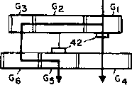
图2是其中一个图1所示离合器组件的放大的剖视图;Figure 2 is an enlarged cross-sectional view of one of the clutch assemblies shown in Figure 1;
图3A-3D是示出了可在图1所示的具有齿轮箱的两根输出轴之间获得的各种相应传动比的简图;3A-3D are diagrams showing various corresponding transmission ratios obtainable between the two output shafts with the gearbox shown in FIG. 1;
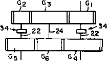
图4A-4B是示出了将从动轴和齿轮设置在各可替换位置上的简图;Figures 4A-4B are diagrams showing alternative positions of the driven shaft and gear;
图5是示出了装有多个从动轴的另一实施例的简图;Figure 5 is a schematic diagram showing another embodiment with a plurality of driven shafts;
图6是示出了将本发明应用到一种四机座轧制设备的简图。Fig. 6 is a schematic diagram showing application of the present invention to a four-stand rolling facility.
请先参阅图1和图2,如图所示,两个轧机机座10、12沿着一条轧制线P连续设置。一般,将这些轧机机座一起组装在一“块体”14内,并且各机座包括一对工作辊16。该工作辊被以悬臂的方式安装在容纳于机座壳体中的辊轴的暴露端上。该辊轴通过输入轴18由内部齿轮传动来驱动。虽然图中未示出,但要明白的是,连续机座的工作辊的轴线错开90°,以便进行无扭转的轧制。这里所有的一切、包括用于轧机机座的内部驱动装置对于那些本技术领域中的熟练人员而言是众所周知的,因此不需要任何进一步的说明。参见例如美国专利5,577,405号和5,280,714号,所揭示的内容在此援引作参考。Please refer to Fig. 1 and Fig. 2 first, as shown in the figure, two rolling mill stands 10, 12 are arranged continuously along a rolling line P. Typically, the mill stands are assembled together in a "block" 14 and each stand includes a pair of
容纳着本发明的一种传动系统的一齿轮箱由标号20表示。该齿轮箱包含着一对驱动轴22,而在该实施例中,还包含一从动轴24。一般由标号26所表示的轴承用作为使驱动轴22及从动轴24绕着平行的轴线转动的轴颈轴承之用。A gearbox housing a transmission system according to the invention is indicated at 20 . The gearbox includes a pair of
联轴器28将驱动轴22与轧机机座的输入轴18相连,其中一驱动轴另外还通过由标号30所表示的联轴器与另一相关的齿轮箱或者驱动电动机(图中未示出)的输出轴相连。A
一第一轮系包括可在驱动轴22上自由转动的互相啮合的驱动齿轮G1、G2,还包括固定于从动轴24并与驱动齿轮G2啮合的一从动齿轮G3。一第二轮系类似地包括可在驱动轴上自由转动的互相啮合的驱动齿轮G4、G5,还包括固定于从动轴并与驱动齿轮G5啮合的一从动齿轮G6。离合器组件34设置在位于各驱动轴上的可自由转动的驱动齿轮之间。A first gear train includes intermeshing drive gears G1 , G2 freely rotatable on
在图2中可清楚地看到,各离合器组件包括一位于驱动轴22上的外齿形环形凸肩36。相邻的驱动齿轮具有圆筒形轴套(hub)38,该轴套终止于结构相似的外齿形环形凸肩40处。一内齿形套筒42固定地与位于轴22上的凸肩36的外齿相啮合,并可在如标号44所示的相反方向上作轴向调节,以便可选择地啮合相邻驱动齿轮的一个或者另一个外齿形凸肩40,从而可选择地进行驱动齿轮与它们相应的驱动轴的可替换的连接。As best seen in FIG. 2 , each clutch pack includes an externally toothed
驱动齿轮G1和G2具有不同齿数,同样驱动齿轮G4和G5的齿数不同,并且从动齿轮G3和G6的齿数也不同。图3A-3D示出了由图1所示的传动系统可得到的不同的驱动传动比。例如,将离合器套筒42调节至如图3A所示的位置,结果驱动传动比将由齿轮G1和G2提供。在图3B中,驱动传动比由齿轮G4和G5提供。在图3C中,驱动传动比由驱动齿轮G2和G4提供,而在图3D中,则由驱动齿轮G1和G5提供。Drive gears G1 and G2 have different numbers of teeth, likewise drive gears G4 and G5 have different numbers of teeth, and driven gears G3 and G6 have different numbers of teeth. 3A-3D illustrate different drive ratios obtainable by the transmission system shown in FIG. 1 . For example, adjusting
因此,在一种三轴与六齿轮的紧凑型结构中可看到,通过简单地调节两个离合器能够可选择地得到介于两根输出轴之间的四种不同的驱动传动比。Thus, in a three-shaft and six-gear compact configuration, four different drive ratios between the two output shafts can be selectively obtained by simply adjusting the two clutches.
本发明易适用于不同的设备布置,例如如4A和4B中所示,图中从动轴24处于不同位置。此外,如图5所示,通过增加一具有从动齿轮G7、G8和离合器48的附加从动轴46,并使得从动齿轮G3、G6可自由地在一从动轴24上转动,其中一附加离合器在两者之间操作,可获得总共六种不同的齿轮传动比。通过增加附加从动轴、从动齿轮和离合器可进一步扩展该原理。通过重复使用在这里所揭示的实施例、或者包含在附加权项范围内的变化型式实施例可获得其它扩展的应用。例如,如图6所示,将三个上述类型的齿轮传送系统A、B和C连接在一起,其中一输入轴48向驱动四个连续的轧机机座(图中未示出)的四根输出轴50a、50b、50c和50d提供功率。在这种设置中,可在轴50a和50b之间、轴50b和50c之间、以及轴50c和50d之间、获得四种传动比,由此对于四机座系列可获得总共六十四种不同的速度组合。The invention is readily adaptable to different plant arrangements, for example as shown in Figures 4A and 4B, where the driven
Claims (5)
Applications Claiming Priority (2)
| Application Number | Priority Date | Filing Date | Title |
|---|---|---|---|
| US09/017,828 | 1998-02-03 | ||
| US09/017,828 US5921152A (en) | 1998-02-03 | 1998-02-03 | Optional multi-ratio gear transmission system |
Publications (2)
| Publication Number | Publication Date |
|---|---|
| CN1225856A CN1225856A (en) | 1999-08-18 |
| CN1096896C true CN1096896C (en) | 2002-12-25 |
Family
ID=21784761
Family Applications (1)
| Application Number | Title | Priority Date | Filing Date |
|---|---|---|---|
| CN99101855A Expired - Lifetime CN1096896C (en) | 1998-02-03 | 1999-02-01 | Optional multi-ratio gear transmission system |
Country Status (11)
| Country | Link |
|---|---|
| US (1) | US5921152A (en) |
| EP (1) | EP0933145B1 (en) |
| JP (1) | JP2980606B2 (en) |
| KR (1) | KR100340659B1 (en) |
| CN (1) | CN1096896C (en) |
| AT (1) | ATE236739T1 (en) |
| BR (1) | BR9900517A (en) |
| CA (1) | CA2259754C (en) |
| DE (1) | DE69906606T2 (en) |
| ES (1) | ES2203010T3 (en) |
| TW (1) | TW419403B (en) |
Families Citing this family (12)
| Publication number | Priority date | Publication date | Assignee | Title |
|---|---|---|---|---|
| FR2862363B1 (en) * | 2003-11-18 | 2007-01-26 | Antonov Automotive Europ | MULTI-REPORTING TRANSMISSION DEVICE, IN PARTICULAR FOR THE AUTOMOBILE |
| ITMI20041526A1 (en) * | 2004-07-28 | 2004-10-28 | Vai Pomini Srl | "MONOBLOCK FINISHER WITH TRANSMISSION RATIO OPTIMIZED FOR A BILLETS LAMINATION SYSTEM" |
| US7191629B1 (en) | 2006-04-13 | 2007-03-20 | Morgan Construction Company | Modular rolling mill |
| US8171767B2 (en) | 2010-06-10 | 2012-05-08 | Siemens Industry, Inc. | Modular rolling mill |
| US8499603B2 (en) | 2010-06-10 | 2013-08-06 | Siemens Industry, Inc. | Modular rolling mill |
| RU2639198C2 (en) * | 2012-05-07 | 2017-12-20 | ПРАЙМЕТАЛЗ ТЕКНОЛОДЖИЗ ЮЭсЭй ЭлЭлСи | Modular rolling mill |
| CN102671957B (en) * | 2012-05-23 | 2014-10-01 | 中冶赛迪工程技术股份有限公司 | Gear transmissions for high-speed rolling mills |
| CN103912666A (en) * | 2014-04-09 | 2014-07-09 | 含山县全兴内燃机配件有限公司 | Self-radiating gearbox |
| CN106409123A (en) * | 2016-11-18 | 2017-02-15 | 辽宁科技大学 | Vertical-roller rolling mill teaching model |
| DE102017210083A1 (en) * | 2017-06-14 | 2018-12-20 | Sms Group Gmbh | Manual transmission in rolling mill technology |
| CN117772796B (en) * | 2024-02-23 | 2024-05-10 | 太原理工大学 | Gear connecting rod type asynchronous rolling mill |
| CN120961633B (en) * | 2025-10-22 | 2025-12-30 | 太原理工大学 | Online multi-gear speed ratio switching asynchronous rolling mill |
Citations (3)
| Publication number | Priority date | Publication date | Assignee | Title |
|---|---|---|---|---|
| US1419770A (en) * | 1920-10-27 | 1922-06-13 | Jr George Q Seaman | Change-speed gearing |
| US4019360A (en) * | 1974-10-01 | 1977-04-26 | Oskar Biernot | Wire rod rolling mill |
| EP0768124A2 (en) * | 1995-10-14 | 1997-04-16 | Daido Tokushuko Kabushiki Kaisha | A method and an apparatus for manufacturing wire |
Family Cites Families (13)
| Publication number | Priority date | Publication date | Assignee | Title |
|---|---|---|---|---|
| CH480884A (en) * | 1967-09-22 | 1969-11-15 | Ceretti Ind Spa | Control unit for rolling mill stands |
| FR1563057A (en) * | 1968-02-16 | 1969-04-11 | ||
| US4024746A (en) * | 1975-01-28 | 1977-05-24 | Demag Aktiengesellschaft | Stand gearing arrangement for the rolls of a continuous rolling mill |
| GB1552787A (en) * | 1976-06-29 | 1979-09-19 | Wilson A I | Rolling mill stand |
| US4325245A (en) * | 1980-03-13 | 1982-04-20 | Sherwood William L | Rolling mill stand |
| GB8332972D0 (en) * | 1983-12-09 | 1984-01-18 | Hille Eng Co Ltd | Rolling mill stand |
| US5076088A (en) * | 1986-04-15 | 1991-12-31 | Mannesmann Ag | Drive for a pilger cold rolling mill |
| DE3614803A1 (en) * | 1986-05-02 | 1987-11-05 | Kocks Technik | GEARBOX FOR DRIVING THE ROLLS OF A ROLLING MILL |
| JPH01180707A (en) * | 1987-12-28 | 1989-07-18 | Nkk Corp | Replaceable rolling mill |
| US4831857A (en) * | 1988-03-18 | 1989-05-23 | Tishken Products Co. | Machine with quick disconnect between spindle drive train and power transmission |
| IT1225195B (en) * | 1988-09-23 | 1990-11-02 | Oto Mills Spa | PROFILING |
| DE69130805T2 (en) * | 1990-10-03 | 1999-11-04 | Hitachi Zosen Corp., Osaka | Device for fastening a work roll in a rolling mill |
| US5595083A (en) * | 1994-08-01 | 1997-01-21 | Morgan Construction Company | Modular rolling mill |
-
1998
- 1998-02-03 US US09/017,828 patent/US5921152A/en not_active Expired - Lifetime
-
1999
- 1999-01-18 CA CA002259754A patent/CA2259754C/en not_active Expired - Fee Related
- 1999-01-21 TW TW088100903A patent/TW419403B/en not_active IP Right Cessation
- 1999-01-26 AT AT99300543T patent/ATE236739T1/en active
- 1999-01-26 DE DE69906606T patent/DE69906606T2/en not_active Expired - Lifetime
- 1999-01-26 EP EP99300543A patent/EP0933145B1/en not_active Expired - Lifetime
- 1999-01-26 ES ES99300543T patent/ES2203010T3/en not_active Expired - Lifetime
- 1999-02-01 CN CN99101855A patent/CN1096896C/en not_active Expired - Lifetime
- 1999-02-02 JP JP11024639A patent/JP2980606B2/en not_active Expired - Fee Related
- 1999-02-02 KR KR1019990003452A patent/KR100340659B1/en not_active Expired - Fee Related
- 1999-02-03 BR BR9900517-4A patent/BR9900517A/en not_active IP Right Cessation
Patent Citations (3)
| Publication number | Priority date | Publication date | Assignee | Title |
|---|---|---|---|---|
| US1419770A (en) * | 1920-10-27 | 1922-06-13 | Jr George Q Seaman | Change-speed gearing |
| US4019360A (en) * | 1974-10-01 | 1977-04-26 | Oskar Biernot | Wire rod rolling mill |
| EP0768124A2 (en) * | 1995-10-14 | 1997-04-16 | Daido Tokushuko Kabushiki Kaisha | A method and an apparatus for manufacturing wire |
Also Published As
| Publication number | Publication date |
|---|---|
| CA2259754A1 (en) | 1999-08-03 |
| JPH11267722A (en) | 1999-10-05 |
| ATE236739T1 (en) | 2003-04-15 |
| US5921152A (en) | 1999-07-13 |
| EP0933145A2 (en) | 1999-08-04 |
| KR19990072380A (en) | 1999-09-27 |
| BR9900517A (en) | 2000-01-04 |
| DE69906606D1 (en) | 2003-05-15 |
| DE69906606T2 (en) | 2004-02-12 |
| ES2203010T3 (en) | 2004-04-01 |
| CA2259754C (en) | 2003-09-16 |
| JP2980606B2 (en) | 1999-11-22 |
| EP0933145A3 (en) | 2002-01-02 |
| TW419403B (en) | 2001-01-21 |
| KR100340659B1 (en) | 2002-06-15 |
| CN1225856A (en) | 1999-08-18 |
| EP0933145B1 (en) | 2003-04-09 |
Similar Documents
| Publication | Publication Date | Title |
|---|---|---|
| CN1096896C (en) | Optional multi-ratio gear transmission system | |
| CN100404910C (en) | Gear mechanism with internal power distribution | |
| US2757556A (en) | Gear drive for rolling mill | |
| KR20010088365A (en) | Rolling mill and rolling mill train | |
| CN1042303C (en) | Finishing mill with two-speed sizing capability | |
| CN212442579U (en) | Single-stand independent transmission modular rolling mill and unit | |
| JPS5852721B2 (en) | rolling mill | |
| CN111318577A (en) | Single-stand independent transmission modular rolling mill and unit | |
| US4385530A (en) | Transmission for driving a stretch-reducing rolling mill | |
| CA2283368C (en) | Rolling mill | |
| MXPA99001141A (en) | Multiple relief gear transmission system option | |
| JP2013531561A (en) | Modular rolling mill | |
| JP2627659B2 (en) | Wire rod block | |
| JP3415792B2 (en) | Roll rolling machine | |
| RU2173589C2 (en) | Apparatus for driving stands of rolling mill with selected speed relation | |
| CN104284740B (en) | Modular rolling mill | |
| CN1051605C (en) | Loaded gear transmission | |
| CN223178084U (en) | Special gear box of trinity multiple roll integration | |
| CN210676367U (en) | High-speed wire module rolling mill | |
| WO2011065659A9 (en) | Transmission device using two control means and a gear assembly | |
| RU14537U1 (en) | BENDING MILL | |
| JPH0539769Y2 (en) | ||
| SU1232323A1 (en) | Arrangement for straightening sheet blanks | |
| SU753506A1 (en) | Differential group drive for continuous rolling mill | |
| KR100279993B1 (en) | 3-axis manual transmission |
Legal Events
| Date | Code | Title | Description |
|---|---|---|---|
| C10 | Entry into substantive examination | ||
| SE01 | Entry into force of request for substantive examination | ||
| C06 | Publication | ||
| PB01 | Publication | ||
| C14 | Grant of patent or utility model | ||
| GR01 | Patent grant | ||
| ASS | Succession or assignment of patent right |
Owner name: SIEMENS BUILDING TECH AG Free format text: FORMER OWNER: MORGAN CONSTRUCTION CO. Effective date: 20100906 |
|
| C41 | Transfer of patent application or patent right or utility model | ||
| COR | Change of bibliographic data |
Free format text: CORRECT: ADDRESS; FROM: MASSACHUSETTS, UNITED STATES TO: GEORGIA, UNITED STATES |
|
| TR01 | Transfer of patent right |
Effective date of registration: 20100906 Address after: American Georgia Patentee after: Siemens Building Tech AG Address before: Massachusetts, USA Patentee before: Morgan Construction Co. |
|
| TR01 | Transfer of patent right | ||
| TR01 | Transfer of patent right |
Effective date of registration: 20161221 Address after: American Georgia Patentee after: Metal technology America Limited Address before: American Georgia Patentee before: Siemens Industry Inc. |
|
| CX01 | Expiry of patent term |
Granted publication date: 20021225 |
|
| CX01 | Expiry of patent term |