Disclosure of Invention
In view of the foregoing, it is necessary to provide a display panel generation method, a display panel generation apparatus, a computer device, a storage medium, and a scan range planning method and device.
A display panel generation method, the method comprising:
obtaining a detection object model image, arranging the detection object model image on a panel to obtain a human body model image display panel,
the detection object model diagram display panel is used for selecting at least one selectable scanning hot area at a designated part, the selectable scanning hot area is used for acquiring a first scanning positioning frame of the designated part, and the selectable scanning hot area can be displayed on the detection object model diagram display panel in one or more layers according to the designated part; and determining the scanning range of the detected object according to the first scanning positioning frame.
A method for automatic scan range planning using a display panel generation method, the method comprising:
respectively acquiring a first scanning positioning frame and a positioning image of the appointed part, wherein the positioning image comprises the appointed part;
and determining a second scanning positioning frame of the appointed part according to the first scanning positioning frame and the positioning image of the appointed part.
In one embodiment, the determining the second scanning positioning frame of the designated part according to the first scanning positioning frame and the positioning image of the designated part comprises:
acquiring first characteristic information in the first scanning positioning frame;
acquiring second characteristic information in the positioning image;
and identifying the first characteristic information and the second characteristic information, and determining a second scanning positioning frame of the designated part.
In one embodiment, the identifying the first feature information and the second feature information, and the determining the second scan positioning frame of the designated part includes:
if the similarity between the first characteristic information in the first scanning positioning frame and the second characteristic information in the positioning image is larger than a preset threshold value, acquiring the range of the second characteristic information in the positioning image, and taking the range of the second characteristic information in the positioning image as a second scanning positioning frame, wherein the second scanning positioning frame is rectangular.
In one embodiment, the acquiring the first scan positioning frame of the designated part comprises:
counting at least one selectable scanning hot area of the appointed part to obtain a hot area set of the appointed part;
establishing a corresponding relation between the designated part hot area set and an automatic positioning model corresponding to the designated part to obtain first incidence relation data;
and establishing a corresponding relation between the specified part hot area set and a scanning protocol to obtain second incidence relation data, wherein the scanning protocol is used for selecting any optional scanning hot area from the specified part hot area set.
In one embodiment, the acquiring the first scan positioning frame of the designated part includes:
selecting an optional scanning hot area from the hot area set of the designated part according to the second incidence relation data and the scanning protocol;
acquiring an automatic positioning model corresponding to the designated part according to the designated part hot area set and the first incidence relation data;
and inputting the selectable scanning hot area into an automatic positioning model corresponding to the appointed part to obtain a first scanning positioning frame of the appointed part.
A display panel generation apparatus, the apparatus comprising:
a display panel generation module for obtaining the detection object model image and setting the detection object model image on the panel to obtain the detection object model image display panel,
the detection object model diagram display panel is used for selecting at least one selectable scanning hot area at a designated part, the selectable scanning hot area is used for acquiring a first scanning positioning frame of the designated part, and the selectable scanning hot area can be displayed on the detection object model diagram display panel in one or more layers according to the designated part; and determining the scanning range of the detected object according to the first scanning positioning frame.
A scan range planning apparatus, the apparatus comprising:
the acquisition device is used for respectively acquiring a first scanning positioning frame and a positioning image of the appointed part, wherein the positioning image comprises the appointed part;
and the positioning frame determining device is used for determining a second scanning positioning frame of the appointed part according to the first scanning positioning frame and the positioning image of the appointed part.
A computer device comprising a memory storing a computer program and a processor implementing the steps of the method as claimed in any one of the above when the computer program is executed.
A computer-readable storage medium, on which a computer program is stored which, when being executed by a processor, carries out the steps of the method according to any one of the preceding claims.
The display panel generation method, the display panel generation device, the computer equipment and the storage medium have the advantages that by acquiring the model image of the detection object, and the detection object model image is arranged on a panel to obtain a detection object model image display panel, wherein the display panel of the model diagram of the detected object is used for selecting at least one selectable scanning hot area at a designated position, the selectable scanning hot area is used for obtaining a first scanning positioning frame of a designated part, the selectable scanning hot area can be displayed on a display panel of the model diagram of the detected object in one or more layers according to the designated part, and the scanning range of the detected object is determined according to the first scanning positioning frame, and further, an automatic scanning range planning method is provided according to the display panel, a scanning positioning frame of the designated part of the detection object is determined, repeated operation is avoided, and the working efficiency is improved.
Detailed Description
In order to make the objects, technical solutions and advantages of the present application more apparent, the present application is described in further detail below with reference to the accompanying drawings and embodiments. It should be understood that the specific embodiments described herein are merely illustrative of the present application and are not intended to limit the present application.
The display panel generation method provided by the application can be applied to the application environment shown in fig. 1. Wherein the terminal 102 communicates with the server 104 through a network. The terminal 102 acquires a detection object model image and transmits the detection object model image to the server 104 through a network. The server 104 sets the detection object model image on a panel to obtain a detection object model map display panel, where the detection object model map display panel is used to select at least one selectable scanning hot area at a specified position, the selectable scanning hot area is used to obtain a first scanning positioning frame at the specified position, the selectable scanning hot area can be displayed on the detection object model map display panel in one or more layers according to the specified position, and a scanning range of a detection object is determined according to the first scanning positioning frame. The terminal 102 may be, but not limited to, various personal computers, notebook computers, smart phones, tablet computers, and portable wearable devices, and the server 104 may be implemented by an independent server or a server cluster formed by a plurality of servers.
In one embodiment, a display panel generating method is provided, which is exemplified by the application of the method to the server in fig. 1, and includes the following steps:
step S1: obtaining a detection object model image, arranging the detection object model image on a panel to obtain a detection object model image display panel,
the detection object model diagram display panel is used for selecting at least one selectable scanning hot area at a designated part, the selectable scanning hot area is used for acquiring a first scanning positioning frame of the designated part, the selectable scanning hot area can be displayed on the detection object model diagram display panel in one or more layers according to the designated part, and the scanning range of a detection object is determined according to the first scanning positioning frame.
Specifically, the detection object model image refers to a detection object diagram that can clearly display each part of the detection object, including a human body, an animal, or other living things. If the detection object is a human body, including a female human body model image and a male human body model image, the standard male or female human body model image can be respectively adopted, or the model can be changed according to different heights and patients. The background color of the human model image display panel and the color of the human model image can not be the same or similar, and in order to better display the human model image on the human model image display panel, the brightness difference between the background color of the human model image display panel and the color of the human model image is preferably set to be the maximum, such as black and white.
The designated region refers to a target region to be scanned, including a head, a chest, or legs, etc. If the head of a patient with an adverse symptom needs to be observed on time, the head, i.e. the designated part, is usually scanned by using a medical imaging device. The detection object model image is acquired before scanning, and the method has the advantages that: time is saved. After obtaining the locating piece of the detection object, the scanning range can be directly obtained and scanned, and the scanning range does not need to be drawn according to the locating piece.
As shown in fig. 2, the head and the upper body are framed on the display panel of the human body model diagram, a head hot area and an upper body hot area are obtained, and the head hot area and the upper body hot area are displayed in two layers because of the possible existence of an intersection area. In addition, in order to clearly display the region of the selectable scanning hot region on the human model map display panel, the region border of the selectable scanning hot region is required to be a color with a large brightness difference from the background color of the human model map display panel.
The selectable scanning hot area refers to an area framed at a designated position, wherein at least one selectable scanning area is provided. As shown in fig. 3, 3 scannable thermal zones are obtained for the head, but not limited to 3, and there is a difference in the area of each scannable thermal zone.
According to the display panel generation method, the detection object model diagram display panel is obtained by obtaining the detection object model image and arranging the detection object model image on the panel, wherein the detection object model diagram display panel is used for selecting at least one selectable scanning hot area at the appointed part, the selectable scanning hot area is used for obtaining the first scanning positioning frame of the appointed part, the selectable scanning hot area can be displayed on the detection object model diagram display panel in one layer or multiple layers according to the appointed part, the scanning range of the detection object is determined according to the first scanning positioning frame, and then the scanning range automatic planning method is provided according to the display panel to determine the scanning positioning frame of the appointed part of the detection object, so that repeated operation is avoided, and the working efficiency is improved.
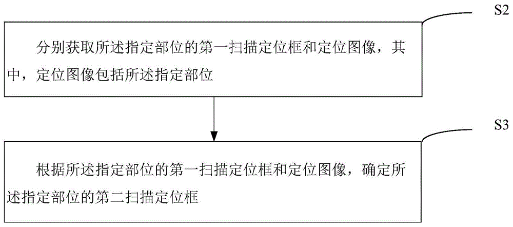
In an embodiment, there is also provided a scan range planning method, as shown in fig. 4, the method including:
step S2: and respectively acquiring a first scanning positioning frame and a positioning image of the appointed part, wherein the positioning image comprises the appointed part.
Specifically, the first scanning positioning frame refers to a preset scanning positioning frame obtained by processing according to the selectable scanning hot area of the designated part, and is used for improving the scanning precision and the operation efficiency.
The positioning image refers to an image containing the designated part of the human body, and if the designated part is the head, the positioning image is correspondingly an image containing the head, and is not limited to the head image, and the positioning image can be acquired through a camera or a laser.
Step S3: and determining a second scanning positioning frame of the appointed part according to the first scanning positioning frame and the positioning image of the appointed part.
Specifically, the second scanning positioning frame refers to a corresponding positioning frame when the designated portion is scanned. If the head of the human body needs to be scanned, after a preset scanning positioning frame of the head is obtained, a positioning image containing the head also needs to be obtained.
The head scanning positioning frame can be obtained by processing the preset scanning positioning frame of the head and the positioning image containing the head.
In one embodiment, as shown in fig. 5, the step S3 includes:
step S31: and acquiring first characteristic information in the first scanning positioning frame.
Specifically, the first feature information refers to a feature region of the designated portion in the preset scanning positioning frame. The feature region is a region included in the medical image of the specific portion. As shown in fig. 6, a preset scan positioning frame, i.e., a rectangular frame, of the head is provided. As shown in fig. 7, a head feature region within a rectangular frame, i.e., a black region in the figure, is provided.
Step S32: and acquiring second characteristic information in the positioning image.
Specifically, the second feature information specifies a feature region of the specified portion in the bit image. As shown in fig. 8, a feature region of a head positioning image is provided, and the head includes 2 divided regions, i.e., a first divided region 10 and a second divided region 20. Wherein the first and second divided areas 10 and 20 are characteristic areas of the head.
Step S33: and identifying the first characteristic information and the second characteristic information, and determining a second scanning positioning frame of the designated part.
Specifically, in conjunction with fig. 7 and 8, two head feature regions are shown, and features of the two head feature regions are identified to determine a head scan positioning frame
In one embodiment, the step S33 includes:
step S331: if the similarity between the first characteristic information in the first scanning positioning frame and the second characteristic information in the positioning image is larger than a preset threshold value, acquiring the range of the second characteristic information in the positioning image, and taking the range of the second characteristic information in the positioning image as a second scanning positioning frame, wherein the second scanning positioning frame is rectangular.
Specifically, the preset threshold refers to a similarity value between first feature information in the first scanning positioning frame and second feature information in the positioning image.
If the similarity is greater than the preset threshold, the black area in fig. 7 is framed with a rectangular frame. As shown in fig. 9, the highest point, the lowest point, the leftmost point, and the rightmost point of the black area are first determined. And setting a plane coordinate system with the lowest point as an origin, wherein the plane coordinate system is respectively an x axis, a y axis and an origin o, respectively drawing straight lines which pass through the leftmost point and the rightmost point and are vertical to the x axis to obtain a left boundary line and a right boundary line, and then drawing straight lines which pass through the highest point and are vertical to the y axis to obtain an upper boundary line. The rectangle formed by the x axis, the left boundary line, the right boundary line and the upper boundary line is the scanning positioning frame of the head.
In one embodiment, as shown in fig. 10, the step S2 includes:
step S4: and counting at least one selectable scanning hot area of the appointed part to obtain the appointed part hot area set.
Specifically, there are 3 selectable scan hotspots in the header, and the 3 scan hotspots are numbered 1, 2, and 3 respectively and are disposed in the header hotspot set.
Step S5: and establishing a corresponding relation between the designated part hot area set and the automatic positioning model corresponding to the designated part to obtain first incidence relation data.
Specifically, the automatic positioning model is a pre-trained model and is used for outputting a preset scanning positioning frame corresponding to the selectable scanning hot area of the designated part, and the preset scanning positioning frame comprises a head automatic positioning model, a chest automatic positioning model, a leg automatic positioning model and the like.
The first association data refers to a data relationship between the set of hotspots at the specified location and the automated model of the specified location. For example, if the head hot zone set is a and the head automatic model is a, the head hot zone set and the head automatic positioning model are in one-to-one correspondence to obtain head association relationship data a-a. And if the chest hot area set is B and the chest automatic positioning model is B, the chest hot area set and the chest automatic positioning model are in one-to-one correspondence to obtain chest incidence relation data B-B. It is also possible that the head hotspot set is an a hotspot, corresponding to 3 models, for example, three hotspots a1, a2, a3 in the head hotspot set, and then three automatic models a1, a2, a3 are corresponding to them. The first association data may also be represented in the form of numbers, texts, or a combination of numbers and texts.
Step S6: and establishing a corresponding relation between the specified part hot area set and a scanning protocol to obtain second incidence relation data, wherein the scanning protocol is used for selecting any optional scanning hot area from the specified part hot area set.
Specifically, the second association data refers to a data relationship between the scan protocol and the hot zone set of the designated portion. For example, if the head hot zone set is 2 and the scanning protocol is 4, the head hot zone set and the head scanning protocol are in one-to-one correspondence, and head scanning association relationship data 2-4 are obtained. The second association data may also be expressed in the form of letters, text, codes, or a combination of numbers and text.
Model images of different standards, hotspots, alignment boxes and their features, protocols, etc. can be updated and augmented by vendor sending update data.
In one embodiment, as shown in fig. 11, the step S2 includes:
step S21: selecting an optional scanning hot area from the hot area set of the designated part according to the second incidence relation data and the scanning protocol;
step S22: acquiring an automatic positioning model corresponding to the designated part according to the designated part hot area set and the first incidence relation data;
step S23: and inputting the selectable scanning hot area into an automatic positioning model corresponding to the appointed part to obtain a first scanning positioning frame of the appointed part.
Specifically, when scanning the head, it is desired to acquire a preset scanning positioning frame of the head. Then, the head hotspot set, the head automatic positioning model and the head scanning protocol may be extracted directly from the first association data and the second association data.
It should be understood that, although the steps in the flowchart of fig. 4 are shown in order as indicated by the arrows, the steps are not necessarily performed in order as indicated by the arrows. The steps are not performed in the exact order shown and described, and may be performed in other orders, unless explicitly stated otherwise. Moreover, at least a portion of the steps in fig. 4 may include multiple sub-steps or multiple stages that are not necessarily performed at the same time, but may be performed at different times, and the order of performance of the sub-steps or stages is not necessarily sequential, but may be performed in turn or alternately with other steps or at least a portion of the sub-steps or stages of other steps.
In one embodiment, there is provided a display panel generating apparatus including: a display panel generation module, wherein:
a display panel generating module 100, configured to obtain a model image of an object to be detected, and set the model image of the object to be detected on a panel to obtain a display panel of the model image of the object to be detected,
the detection object model diagram display panel is used for selecting at least one selectable scanning hot area at a designated part, the selectable scanning hot area is used for acquiring a first scanning positioning frame of the designated part, the selectable scanning hot area can be displayed on the detection object model diagram display panel in one or more layers according to the designated part, and the scanning range of a detection object is determined according to the first scanning positioning frame.
In one embodiment, as shown in fig. 12, there is provided a scan range planning apparatus including: the device comprises an acquisition module and a positioning frame determination module, wherein:
an obtaining module 200, configured to obtain a first scanning positioning frame and a positioning image of the designated portion, respectively, where the positioning image includes the designated portion;
and a positioning frame determining module 300, configured to determine a second scanning positioning frame of the designated portion according to the first scanning positioning frame and the positioning image of the designated portion.
In one embodiment, the location box determining module 300 includes:
a first feature information obtaining module 301, configured to obtain first feature information in the first scanning positioning frame;
a second feature information obtaining module 302, configured to obtain second feature information in the positioning image;
and an identifying module 303, configured to identify the first feature information and the second feature information, and determine a second scanning positioning frame of the designated portion.
In one embodiment, the identification module 303 comprises:
a second scanning positioning frame obtaining module 3031, configured to obtain a range of second feature information in the positioning image if a similarity between the first feature information in the first scanning positioning frame and the second feature information in the positioning image is greater than a preset threshold, and use the range of the second feature information in the positioning image as the second scanning positioning frame, where the second scanning positioning frame is a rectangle.
In one embodiment, the obtaining module 200 comprises:
a counting module 400, configured to count at least one selectable scanning hot area of the designated portion, to obtain a hot area set of the designated portion;
a first association relation data obtaining module 500, configured to establish a correspondence between the designated portion hot area set and an automatic positioning model corresponding to the designated portion, so as to obtain first association relation data;
a second association relation data obtaining module 600, configured to establish a corresponding relation between the specified portion hot area set and a scanning protocol, so as to obtain second association relation data, where the scanning protocol is used to select any selectable scanning hot area from the specified portion hot area set.
In one embodiment, the obtaining module 200 includes:
an optional scanning hot area obtaining module 201, configured to select an optional scanning hot area from the hot area set at the specified location according to the second association relation data and the scanning protocol;
an automatic positioning model obtaining module 202, configured to obtain an automatic positioning model corresponding to the specified portion according to the specified portion hot zone set and the first association relation data;
a first scanning positioning frame obtaining module 203, configured to input the selectable scanning hot area into the automatic positioning model corresponding to the specified portion, so as to obtain a first scanning positioning frame of the specified portion.
In one embodiment, there is also provided a scan range planning apparatus, the apparatus comprising:
the acquisition device is used for respectively acquiring a first scanning positioning frame and a positioning image of the appointed part, wherein the positioning image comprises the appointed part;
and the positioning frame determining device is used for determining a second scanning positioning frame of the appointed part according to the first scanning positioning frame and the positioning image of the appointed part.
For specific limitations of the display panel generation apparatus, reference may be made to the above limitations of the display panel generation method, which are not described herein again. The modules in the display panel generation apparatus may be implemented in whole or in part by software, hardware, and a combination thereof. The modules can be embedded in a hardware form or independent from a processor in the computer device, and can also be stored in a memory in the computer device in a software form, so that the processor can call and execute operations corresponding to the modules.
In one embodiment, a computer device is provided, which may be a server, and its internal structure diagram may be as shown in fig. 13. The computer device includes a processor, a memory, a network interface, and a database connected by a system bus. Wherein the processor of the computer device is configured to provide computing and control capabilities. The memory of the computer device comprises a nonvolatile storage medium and an internal memory. The non-volatile storage medium stores an operating system, a computer program, and a database. The internal memory provides an environment for the operation of an operating system and computer programs in the non-volatile storage medium. The database of the computer device is used to store panel generation data. The network interface of the computer device is used for communicating with an external terminal through a network connection. The computer program is executed by a processor to implement a display panel generation method.
Those skilled in the art will appreciate that the architecture shown in fig. 13 is merely a block diagram of some of the structures associated with the disclosed aspects and is not intended to limit the computing devices to which the disclosed aspects apply, as particular computing devices may include more or less components than those shown, or may combine certain components, or have a different arrangement of components.
In an embodiment, a computer device is provided, comprising a memory in which a computer program is stored and a processor which, when executing the computer program, carries out the steps of the method as claimed in any of the above.
In an embodiment, a computer-readable storage medium is provided, on which a computer program is stored, which computer program, when being executed by a processor, carries out the steps of the method as set forth in any of the above.
It will be understood by those skilled in the art that all or part of the processes of the methods of the embodiments described above can be implemented by hardware instructions of a computer program, which can be stored in a non-volatile computer-readable storage medium, and when executed, can include the processes of the embodiments of the methods described above. Any reference to memory, storage, database, or other medium used in the embodiments provided herein may include non-volatile and/or volatile memory, among others. Non-volatile memory can include read-only memory (ROM), Programmable ROM (PROM), Electrically Programmable ROM (EPROM), Electrically Erasable Programmable ROM (EEPROM), or flash memory. Volatile memory can include Random Access Memory (RAM) or external cache memory. By way of illustration and not limitation, RAM is available in a variety of forms such as Static RAM (SRAM), Dynamic RAM (DRAM), Synchronous DRAM (SDRAM), Double Data Rate SDRAM (DDRSDRAM), Enhanced SDRAM (ESDRAM), Synchronous Link DRAM (SLDRAM), Rambus Direct RAM (RDRAM), direct bus dynamic RAM (DRDRAM), and memory bus dynamic RAM (RDRAM).
The technical features of the above embodiments can be arbitrarily combined, and for the sake of brevity, all possible combinations of the technical features in the above embodiments are not described, but should be considered as the scope of the present specification as long as there is no contradiction between the combinations of the technical features.
The above-mentioned embodiments only express several embodiments of the present application, and the description thereof is more specific and detailed, but not construed as limiting the scope of the invention. It should be noted that, for a person skilled in the art, several variations and modifications can be made without departing from the concept of the present application, which falls within the scope of protection of the present application. Therefore, the protection scope of the present patent shall be subject to the appended claims.