Grid-connected inverter power oscillation suppression system and method
Technical Field
The invention relates to the field of electricity, in particular to a grid-connected inverter power oscillation suppression system and a grid-connected inverter power oscillation suppression method.
Background
The common suppression algorithm for the inverter grid-connected system oscillation at present comprises the following steps: lead-lag compensation, virtual impedance, adaptive control, etc. The lead-lag compensation method is characterized in that a lead-lag compensator is added in an inverter current loop, and the phase angle margin of a closed loop system is improved by designing a lead-lag time constant, so that the effect of improving stability and inhibiting oscillation is achieved. The method has the main problems that the parameter design is too complex, the control response speed is inevitably reduced by the lead-lag calculation, the control response speed only acts on a certain specific power grid, and the like; the virtual impedance rule is to feed back an ac voltage and a current to form a virtual impedance, and to increase a phase angle margin to suppress oscillation. The problem with this approach is also that the parameter design is too complex and only works for a certain specific grid, etc.; the self-adaptive control is to utilize alternating voltage feedforward to weaken the influence of the power grid impedance change on the inverter control and inhibit the oscillation problem caused by the power grid impedance change by measuring the power grid impedance in real time and using the parameters of the power grid impedance to generate alternating voltage. The problem with this approach is that additional current and voltage sensors need to be introduced, which increases the hardware cost of the inverter, and secondly, calculating the impedance will also reduce the control response speed, etc.
Disclosure of Invention
The control algorithm provided by the invention is a grid-connected inverter power oscillation suppression strategy based on inverter direct-current voltage differential feedback.
A power oscillation suppression system of a grid-connected inverter is characterized in that a voltage feedback device is added on a direct current side, and the voltage feedback device is used for measuring a voltage instantaneous value on the direct current side and feeding the voltage instantaneous value back to a voltage loop and a current loop for input.
In the above grid-connected inverter power oscillation suppression system, the voltage feedback device includes:
the resistance voltage division network consists of a resistor and a measuring probe and is used for measuring the instantaneous value of the voltage on the direct current side;
the sampling filtering module consists of a filtering circuit and is used for performing low-pass sampling filtering on the measured direct-current voltage;
the proportional operation module consists of two voltage followers and is used for carrying out proportional operation on the sampled signals and respectively feeding the signals back to the voltage loop and the current loop for input;
and the differential operation module is composed of an amplifier circuit and is used for carrying out differential operation on the two paths of feedback signals to obtain a final feedback signal.
A method for suppressing power oscillation of a grid-connected inverter is characterized in that,
step 1, selecting feedback direct current voltage differential to input of a voltage loop, analyzing a physical mechanism, equivalently connecting a resistor in series at a direct current side, and consuming oscillation energy by a virtual resistor.
Step 2, feeding back the direct current capacitor voltage differential to a current loop for input, wherein the direct current is fed back to a direct current voltage instruction value after being connected in parallel through a differential link and a proportional link, and the direct current voltage instruction value is equivalent to connecting a resistor and an inductor in series on a direct current side, so that the oscillation frequency of a system is changed, and the oscillation risk is reduced; on the other hand, the oscillation energy is "dissipated" by the series dummy resistor.
In the method for suppressing the power oscillation of the grid-connected inverter, the feedback method specifically comprises the following steps:
step 1, selecting a feedback variable;
according to the instantaneous power theory, the AC side and the DC side of the inverter satisfy the instantaneous power balance relation:
P in +P dc =P out (1)
carrying out small-signal processing on the formula (1):
the essence of the power oscillation is that the damping action of the grid-connected inverter system is reduced due to the increase of the impedance of a power grid, so that the input and output power deviation of the inverter is difficult to balance in a short time after the system is disturbed. As can be seen from equation (2), the input/output power deviation of the inverter is proportional to the differential amount of the dc voltage under a small disturbance, and the essence of the active damping is feedback control of the scale variable corresponding to the system oscillation frequency. In conclusion, suppression of system power oscillation selects the direct-current voltage differential as the feedback variable.
And 2, selecting a feedback introduction point, wherein the feedback introduction point comprises a voltage loop input and a current loop input.
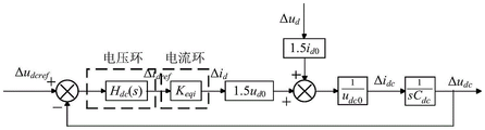
In the oscillation process, the phase of an alternating current side can be always tracked by the phase-locked loop, the grid-connected current can always follow a grid-connected current instruction value, the tracking process is equivalent by a proportionality coefficient Keqi, meanwhile, the dq axis coupling effect is ignored, and only the d axis active power is considered. The feedback variable can be fed back to the voltage loop input, as can be seen from fig. 3, by changing the node position in the control block diagram, it is concluded that the dc-side reference voltage after feedback is formed by subtracting a value from the original reference voltage, where the value can be formed by multiplying the dc current by a coefficient related to the feedback coefficient and the dc capacitor, and the coefficient is the virtual resistance. The physical mechanism of the feedback action is therefore equivalent to connecting a resistor in series on the dc side, the energy of the oscillation being "dissipated" by a dummy resistor.
The feedback variable is fed back to the current loop input, the node position and the summing point position are sequentially changed, the direct current side reference voltage after conclusion feedback is obtained by subtracting a value on the basis of the original reference voltage, the value can be formed by multiplying direct current by a coefficient related to a PI parameter, a direct current capacitor and a feedback coefficient controlled by the direct current voltage, the coefficient is further subjected to formula transformation, the coefficient is obtained by connecting a proportion link and a differential link in parallel, and the proportion link and the differential link correspond to a virtual resistor and a virtual inductor. Therefore, the physical mechanism of the feedback action is that a resistor and an inductor are connected in series on the direct current side, so that the oscillation frequency of the system is changed, and the oscillation risk is reduced; on the other hand, the oscillation energy is "dissipated" by the series-connected dummy resistors.
According to the invention, through feeding back the direct-current voltage differential to the corresponding control link and carrying out corresponding feedback parameter configuration, the suppression of grid-connected system power oscillation is realized, and the adaptability range and the control parameter domain of the power grid are greatly improved. The invention has the advantages of obvious effect, simple structure, no increase of other external hardware cost, applicability to weak power grids in a larger range, and strong robustness to control loop parameter disturbance.
Description of the drawings:
fig. 1 shows an inverter topology and a conventional control algorithm according to the present invention.
Fig. 2 is a block diagram of a power oscillation suppression strategy control according to the present invention.
FIG. 3 is a block diagram transformation process of a feedback variable to a voltage loop input.
Fig. 4 is a block diagram transformation process of a feedback variable to a current loop input.
Fig. 5 is a block diagram of a power oscillation suppression strategy control according to the present invention.
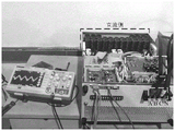
FIG. 6 is a diagram of an experimental prototype according to the present invention.
Fig. 7 shows the experimental result of the power grid inductance of 2.5mH under the conventional control of the present invention.
FIG. 8 shows the experimental results of the power grid inductance of 2.5mH after the control algorithm of the present invention is applied.
Fig. 9 shows the experimental result of the power grid inductance of 10mH after the control algorithm of the invention is adopted.
Detailed Description
The present invention will be described in further detail with reference to the attached drawings and examples for facilitating understanding and implementation of the present invention by those of ordinary skill in the art, and it is to be understood that the implementation examples described herein are only for illustrating and explaining the present invention and are not to be construed as limiting the present invention.
1. First, the system to which the present invention relates will be described.
The invention mainly adds a voltage feedback device on the direct current side, and the voltage feedback device is used for measuring the voltage instantaneous value of the direct current side and feeding the voltage instantaneous value back to the input of a voltage loop and a current loop.
The voltage feedback device includes:
the resistance voltage dividing network consists of a resistor and a measuring probe and is used for measuring the voltage instantaneous value of the direct current side;
the sampling filtering module consists of a filtering circuit and is used for performing low-pass sampling filtering on the measured direct-current voltage;
the proportional operation module consists of two voltage followers and is used for carrying out proportional operation on the sampled signals and respectively feeding the signals back to the voltage loop and the current loop for input;
and the differential operation module is composed of an amplifier circuit and is used for carrying out differential operation on the two paths of feedback signals to obtain a final feedback signal.
2. The invention also relates to a power oscillation suppression method of the grid-connected inverter, which comprises the steps of
The feedback direct current voltage differential is selected to be input to a voltage loop, the physical mechanism of the voltage loop is analyzed, the direct current voltage differential is equivalent to a resistor connected in series at the direct current side, and the oscillation energy is consumed by a virtual resistor.
The direct current capacitor voltage differential is fed back to the current loop input, the direct current is fed back to the direct current voltage instruction value after being connected in parallel through the differential link and the proportional link, and the direct current voltage instruction value is equivalent to connecting a resistor and an inductor in series on the direct current side, so that the oscillation frequency of the system is changed, and the oscillation risk is reduced; on the other hand, the oscillation energy is "dissipated" by the series dummy resistor.
The specific method for feedback is as follows:
step 1, selecting a feedback variable;
according to the instantaneous power theory, the AC side and the DC side of the inverter satisfy the instantaneous power balance relation:
P in +P dc =P out (1)
carrying out small-signal processing on the formula (1):
the essence of the power oscillation is that the damping action of the grid-connected inverter system is reduced due to the increase of the impedance of a power grid, so that the input and output power deviation of the inverter is difficult to balance in a short time after the system is disturbed. As can be seen from equation (2), the input/output power deviation of the inverter is proportional to the differential amount of the dc voltage under a small disturbance, and the essence of the active damping is the feedback control of the scale variable corresponding to the system oscillation frequency. In conclusion, suppression of system power oscillation selects the direct-current voltage differential as the feedback variable.
Step 2, selecting a feedback introduction point
The inverter topology and the conventional control algorithm to which the present invention relates are shown in fig. 1, in which the alternative points of introduction are voltage loop input and current loop input. In the oscillation process, the phase of the phase-locked loop can be always tracked by considering that the phase of the phase-locked loop on the AC side and the grid-connected current can always follow the command value of the grid-connected current, and the proportional coefficient K is used in the tracking process eqi Equivalently, only d-axis active power is considered while ignoring dq-axis coupling effects. A block diagram of a derivable inverter control structure small signal is shown in fig. 2.
The feedback variable is fed back to the input of the voltage loop, and the physical mechanism of the feedback variable can be obtained through simple block diagram conversion, fig. 3 is a block diagram conversion process, the feedback function is to feed back the direct current to the direct current voltage instruction value through a proportion link, which is equivalent to connecting a resistor in series at the direct current side, and the oscillating energy is consumed by a virtual resistor.
The feedback variable is fed back to the current loop input, and the physical mechanism is obtained through block diagram conversion, and fig. 4 is a corresponding block diagram conversion process. The feedback function is that the direct current is fed back to a direct current voltage instruction value after being connected in parallel through a differential link and a proportional link, which is equivalent to connecting a resistor and an inductor in series on a direct current side, so that the oscillation frequency of the system is changed, and the oscillation risk is reduced; on the other hand, the oscillation energy is "dissipated" by the series-connected dummy resistors.
In summary, the present invention proposes a power oscillation suppression strategy that includes both feedback introduced to the voltage loop input and the current loop input. The control block diagram is shown in fig. 5.
3. The following is a specific case of using the above system and method.
A principle prototype of a 20kW three-phase grid-connected inverter is built, and is shown in FIG. 6. TMS320F28335 is used as a control chip for a prototype, the direct current voltage of the prototype is 800V, and the effective value of the alternating current voltage is 380V. The power tube adopts an NPT module VS-GB100TH120U of Vishay Semiconductor company, and adopts a voltage and current sensor for sampling. In the experiment, the commercial power and the inductance are directly used for simulating the weak power grid condition, and the power grid inductance is changed between 2.5mH and 10 mH. The inverter control algorithm is shown in fig. 1 and 5.
And (3) working condition analysis:
and selecting a larger grid inductance Lg =2.5mH as a comparison waveform. The dc voltage and ac current waveforms obtained from the experiment are shown in fig. 7. Because the inductance of the power grid is large enough, the inverter control parameters designed based on the strong power grid are not suitable for the weak power grid, and the system generates power oscillation until the direct current voltage waveform is constant amplitude oscillation with the frequency of about 5Hz and the amplitude of about 150V.
When the inductance of the power grid is continuously increased, if the traditional control mode is maintained unchanged, the electric quantity of the alternating current side and the direct current side of the inverter generates oscillation and dispersion, so that the system is unstable, irreparable damage is caused to an experimental prototype, and the part of experiment is not carried out. When the power oscillation active damping strategy provided by the invention is adopted, the experimental result is shown in fig. 8, the oscillation of direct current voltage and grid-connected current is quickly attenuated, the system is quickly recovered and stabilized, and the adjusting time is about ts =0.6s. This shows that the power oscillation active damping strategy proposed by the present invention suppresses the power oscillation of the system under the weak grid. Fig. 9 shows dc voltage and grid-connected current waveforms obtained by selecting a large grid inductance Lg =10mH for experiments. The oscillation of the direct-current voltage and the grid-connected current gradually attenuates with the lapse of time, and the adjustment time ts =1.6s. The control algorithm provided by the invention can greatly improve the applicability of the inverter to the weak grid range.
The specific embodiments described herein are merely illustrative of the spirit of the invention. Various modifications or additions may be made to the described embodiments, or alternatives may be employed, by those skilled in the art, without departing from the spirit or ambit of the invention as defined in the appended claims.