CN109802483B - Multiphase motor channel fault ride-through operation control method - Google Patents
Multiphase motor channel fault ride-through operation control method Download PDFInfo
- Publication number
- CN109802483B CN109802483B CN201811651809.5A CN201811651809A CN109802483B CN 109802483 B CN109802483 B CN 109802483B CN 201811651809 A CN201811651809 A CN 201811651809A CN 109802483 B CN109802483 B CN 109802483B
- Authority
- CN
- China
- Prior art keywords
- current
- channel
- voltage
- fault
- bridge arm
- Prior art date
- Legal status (The legal status is an assumption and is not a legal conclusion. Google has not performed a legal analysis and makes no representation as to the accuracy of the status listed.)
- Active
Links
- 238000000034 method Methods 0.000 title claims abstract description 45
- 238000004804 winding Methods 0.000 claims abstract description 55
- 230000008569 process Effects 0.000 claims abstract description 18
- 238000006243 chemical reaction Methods 0.000 claims abstract description 11
- 230000006641 stabilisation Effects 0.000 claims abstract description 7
- 238000011105 stabilization Methods 0.000 claims abstract description 7
- 230000004907 flux Effects 0.000 claims description 65
- 230000001052 transient effect Effects 0.000 claims description 57
- 238000004146 energy storage Methods 0.000 claims description 41
- 239000003990 capacitor Substances 0.000 claims description 37
- 230000002457 bidirectional effect Effects 0.000 claims description 27
- 239000013598 vector Substances 0.000 claims description 27
- 230000001360 synchronised effect Effects 0.000 claims description 22
- 238000012937 correction Methods 0.000 claims description 20
- 230000007704 transition Effects 0.000 claims description 17
- 230000003068 static effect Effects 0.000 claims description 11
- 230000000903 blocking effect Effects 0.000 claims description 10
- 238000001914 filtration Methods 0.000 claims description 10
- 238000007599 discharging Methods 0.000 claims description 9
- 238000005516 engineering process Methods 0.000 claims description 9
- 230000001960 triggered effect Effects 0.000 claims description 8
- 230000001276 controlling effect Effects 0.000 claims description 7
- 230000010363 phase shift Effects 0.000 claims description 7
- 230000002238 attenuated effect Effects 0.000 claims description 5
- 230000008878 coupling Effects 0.000 claims description 5
- 238000010168 coupling process Methods 0.000 claims description 5
- 238000005859 coupling reaction Methods 0.000 claims description 5
- 230000035945 sensitivity Effects 0.000 claims description 4
- 238000013016 damping Methods 0.000 claims description 3
- 230000005284 excitation Effects 0.000 claims description 3
- 230000006698 induction Effects 0.000 claims description 3
- 230000001105 regulatory effect Effects 0.000 claims description 3
- 230000015572 biosynthetic process Effects 0.000 claims description 2
- 238000012512 characterization method Methods 0.000 claims description 2
- 238000003786 synthesis reaction Methods 0.000 claims description 2
- 230000010354 integration Effects 0.000 claims 2
- 238000010248 power generation Methods 0.000 abstract description 3
- 238000010586 diagram Methods 0.000 description 17
- 239000011159 matrix material Substances 0.000 description 7
- 230000000087 stabilizing effect Effects 0.000 description 6
- 230000009466 transformation Effects 0.000 description 6
- 230000033228 biological regulation Effects 0.000 description 5
- 238000011217 control strategy Methods 0.000 description 4
- 230000008901 benefit Effects 0.000 description 3
- 230000005540 biological transmission Effects 0.000 description 3
- 238000005520 cutting process Methods 0.000 description 3
- 238000011160 research Methods 0.000 description 3
- 239000000126 substance Substances 0.000 description 3
- 229910000831 Steel Inorganic materials 0.000 description 2
- 238000011161 development Methods 0.000 description 2
- 230000018109 developmental process Effects 0.000 description 2
- 238000005265 energy consumption Methods 0.000 description 2
- 238000005272 metallurgy Methods 0.000 description 2
- 238000005065 mining Methods 0.000 description 2
- 230000009467 reduction Effects 0.000 description 2
- 238000005096 rolling process Methods 0.000 description 2
- 239000010959 steel Substances 0.000 description 2
- 230000001629 suppression Effects 0.000 description 2
- 238000012546 transfer Methods 0.000 description 2
- 241001270131 Agaricus moelleri Species 0.000 description 1
- XEEYBQQBJWHFJM-UHFFFAOYSA-N Iron Chemical group [Fe] XEEYBQQBJWHFJM-UHFFFAOYSA-N 0.000 description 1
- 241000949477 Toona ciliata Species 0.000 description 1
- 238000004458 analytical method Methods 0.000 description 1
- 230000009286 beneficial effect Effects 0.000 description 1
- 238000004364 calculation method Methods 0.000 description 1
- 230000008859 change Effects 0.000 description 1
- 239000011162 core material Substances 0.000 description 1
- 238000009826 distribution Methods 0.000 description 1
- 230000000694 effects Effects 0.000 description 1
- 238000002347 injection Methods 0.000 description 1
- 239000007924 injection Substances 0.000 description 1
- 230000016507 interphase Effects 0.000 description 1
- 238000012986 modification Methods 0.000 description 1
- 230000004048 modification Effects 0.000 description 1
- 230000010355 oscillation Effects 0.000 description 1
- 230000010349 pulsation Effects 0.000 description 1
- 239000000243 solution Substances 0.000 description 1
- 230000002194 synthesizing effect Effects 0.000 description 1
- 230000033772 system development Effects 0.000 description 1
Images




Classifications
-
- Y—GENERAL TAGGING OF NEW TECHNOLOGICAL DEVELOPMENTS; GENERAL TAGGING OF CROSS-SECTIONAL TECHNOLOGIES SPANNING OVER SEVERAL SECTIONS OF THE IPC; TECHNICAL SUBJECTS COVERED BY FORMER USPC CROSS-REFERENCE ART COLLECTIONS [XRACs] AND DIGESTS
- Y02—TECHNOLOGIES OR APPLICATIONS FOR MITIGATION OR ADAPTATION AGAINST CLIMATE CHANGE
- Y02B—CLIMATE CHANGE MITIGATION TECHNOLOGIES RELATED TO BUILDINGS, e.g. HOUSING, HOUSE APPLIANCES OR RELATED END-USER APPLICATIONS
- Y02B10/00—Integration of renewable energy sources in buildings
- Y02B10/70—Hybrid systems, e.g. uninterruptible or back-up power supplies integrating renewable energies
Landscapes
- Control Of Ac Motors In General (AREA)
- Inverter Devices (AREA)
Abstract
The invention discloses a multiphase motor channel fault ride-through operation control method, which can carry out fault-tolerant on-line channel switching without stopping and ride-through operation when one or more channels have faults; in the process of channel fault and fault channel removal, implementing overcurrent protection of the AC side (namely the motor winding side) of the inverter of the residual operation channel, voltage stabilization control of the DC bus side of the inverter and an inverter magnetic field compensation comprehensive coordination control scheme; the method realizes the rapid, stable and safe fault-tolerant on-line channel switching non-stop traversing operation of the multi-channel motor, and can be applied to high-power electromechanical energy conversion occasions such as ship propulsion, rail traction, wind power generation and the like.
Description
Technical Field
The invention belongs to the technical field of alternating current motor control, and particularly relates to a multi-channel operation channel fault online cutting non-stop traversing operation control method for a multi-phase motor, which is used for realizing rapid, stable and safe multi-channel online cutting non-stop traversing operation of the motor and is applied to high-power electromechanical energy conversion occasions such as ship propulsion, rail traction, mining machinery transmission, metallurgy steel rolling, fan and pump speed regulation, wind power generation and the like.
Background
With the development of power electronic devices and technologies, the power converter can break through the traditional three-phase mode and adopt a multi-phase mode, so that the motor is free from the limitation of the number of phases of a power grid.
Compared with a three-phase motor, the multi-phase motor (the number of phases m > 3) has the following significant advantages: firstly, a low-voltage high-power transmission system and a high-power application occasion with limited power supply voltage can be realized by using low-voltage and power-grade devices in a multi-phase mode; secondly, along with the increase of the number of phases, the times of space harmonic magnetomotive force generated by fundamental wave current of the motor are increased, and the amplitude is reduced, so that the torque ripple frequency is increased, the amplitude is reduced, the operation efficiency of the motor is also improved, and the vibration noise is also improved; thirdly, due to the redundancy of the number of phases of the multi-phase motor, when one or more phases of the multi-phase motor or the inverter have faults, derating fault-tolerant operation is realized by adjusting a control strategy, so that the operation reliability of the motor is improved; fourthly, the controllable dimension of the motor is equal to the independent phase number of the motor.
Therefore, the control freedom degree of the multi-phase motor is more, and the control is more flexible. For example, for a full-pitch winding multi-phase motor, non-sinusoidal power supply is realized in a low-order harmonic injection mode, so that the distribution of an air gap magnetic field is a flat-top wave, the utilization rate of an iron core material is improved, and the power and the torque density of the motor are increased. In view of this, the multiphase motor system has a wide application value in the fields of high-power electromechanical energy conversion such as ship propulsion, rail traction, mining machinery transmission, metallurgy steel rolling, fan and pump speed regulation, wind power generation and the like, and research on the multiphase motor control technology is also developed accordingly.
Classical control strategies for multiphase motors include field oriented vector control, direct torque/power control, etc. The vector control adopts closed-loop control on the flux linkage and the electromagnetic torque through coordinate transformation respectively, so that decoupling of a magnetic field and current is realized, and good dynamic and static performances are achieved; and the direct control does not need over elaborate coordinate transformation, and has higher dynamic performance and robustness through the direct tracking of flux linkage and torque/power.
However, the increase of the number of motor phases and control dimensions of the toggle control also has the disadvantages of complex control strategy, huge single power converter control system and the like in a multi-phase system, thereby increasing the technical difficulty of system development and being restricted by the development.
The idea of multi-channel control of the multi-phase motor is to use a plurality of sets of power converters to drive one motor, and convert multi-phase integral drive with high technical difficulty into multi-channel decentralized drive with mature technology, so that the technical problem of complex multi-phase systems is better solved, and system redundancy and fault tolerance are improved because each channel converter is an independent unit. The control idea is a new way and becomes a research hotspot of a multiphase motor system.
In order to fully exert the high reliability advantage of a multi-phase system, the system is required to be capable of carrying out non-stop ride-through operation on an online channel switching when one or more channels are in fault, however, a motor is an electromagnetic coupling whole, in the transient process of channel fault or channel switching, due to the fact that voltage and current of a stator winding of the motor are suddenly changed, transient magnetic chains of the stator winding are changed, impact current and bus overvoltage are generated in the rest operating channels, fault shutdown is caused, and the online channel switching is failed. For example, a terminal voltage suddenly changes due to single-phase-to-ground or interphase short circuit of a stator winding of a certain channel, a negative-sequence and transient direct-current static magnetic field can be generated in the motor, a high back electromotive force is induced by a rotor winding or other stator windings, a transient large current is generated, electromagnetic torque sudden change, pulsation and oscillation are caused, a direct-current bus voltage pump rises, faults such as overcurrent or overvoltage are caused, and even system components are damaged.
At present, detailed research on control of a transition process among normal, fault and fault-tolerant working conditions is lacked, so that fault-tolerant operation is difficult to apply to actual engineering. How to independently protect and coordinate each channel in the fault crossing operation of the channel is a new urgent problem which is caused by the adoption of a multi-channel mode of a motor, and the analysis of the problem and the seeking of a solution method have both theoretical significance and practical value.
Disclosure of Invention
The invention aims to provide a fault ride-through operation control method for a multi-channel operation channel of a multi-phase motor, which can realize fault-tolerant on-line channel switching without stopping and ride-through operation when one or more channels have faults; in the process of channel fault and fault channel removal, implementing overcurrent protection of the AC side (namely the motor winding side) of the inverter, voltage stabilization control of the DC side of the inverter and comprehensive coordination control of magnetic field compensation of the multi-phase motor on the rest operating channels; the influence of the transient component of the stator flux linkage on the motor is quickly inhibited, and the surge impact current of an attenuation channel is inhibited and accelerated, so that the rapid, stable and safe fault-tolerant cross-over operation of the multi-channel multi-phase motor in the transition process of on-line channel switching is realized.
The technical scheme adopted by the invention for solving the technical problem is as follows: a multiphase motor channel fault ride-through operation control method is based on a plurality of converter channels connected with a multiphase motor bridge arm and a winding, and comprises overcurrent protection on an alternating current side (namely a motor winding side) of a non-fault channel inverter, voltage stabilization control on a direct current side of the non-fault channel inverter and magnetic field compensation control of the non-fault channel inverter on the multiphase motor in a fault ride-through transition process; the over-current protection of the alternating current side (namely the motor winding side) of the inverter adopts an active shunt circuit to provide a passage for transient impact surge current, so that the impact surge current flowing through the stator winding of the residual non-fault channel is transferred from the bypass of the inverter and is consumed on a current-limiting resistor; the energy storage circuit is provided with a voltage type energy storage medium, a three-level multiple phase-shift direct-current bidirectional voltage source converter is used as an energy conversion control interface of a direct-current bus and the energy storage medium, the voltage and current stress of a switching device is reduced, the ripple wave filtering quality is improved, a filter is reduced, fault-tolerant operation can be realized, and the load shedding circuit adopts a chopper topology; the magnetic field compensation control generates a current space vector and a corresponding flux linkage component in a phase opposite to that of a fault channel stator transient flux linkage in a non-fault channel, and counteracts the influence of the transient component of the fault channel stator flux linkage on the motor; and after the system channel fails and the impact on the motor is restrained and attenuated in the on-line channel switching transition process, the multi-phase motor operates in a fault-tolerant mode through a non-failure channel.
Furthermore, the shunt circuit is an active topology composed of a multiphase (the phase number is the phase number of one channel) full-control power switch device and a current-limiting resistor, and adopts a multiphase power switch tube such as a bidirectional Insulated Gate Bipolar Transistor (IGBT) anti-parallel connection type bidirectional switch structure, or a multiphase switch tube common emitter series connection type bidirectional switch structure, or a multiphase switch tube parallel connection diode bridge type bidirectional switch structure, or a multiphase diode rectification connection switch tube structure; the controller of each channel shunt circuit uses the channel stator winding current i ac As input, if the winding current is lower than the lower limit safety threshold current of the inverter capacity, the shunt circuit switch tube is blocked, the shunt circuit is closed, the inverter works, if the winding current is higher than or equal to the upper limit safety threshold current of the inverter capacity, the shunt circuit switch tube is triggered, the shunt circuit is conducted, and simultaneously all devices in the inverter are turned off, so that transient surge impact current flows through the current limiting resistor, and the inverter is bypassed, and the transient surge current of the winding is attenuated by using the current limiting resistor to consume redundant energy of the winding; the shunt circuit adopts a hysteresis mode to determine the on or off of the power switch device.
Further, the three-level multiple phase-shift dc bi-directional voltage source converter is a capacitance-clamped three-level multiple phase-shift dc bi-directional voltage source converter, and the circuit topology thereof is as follows: switch tube S j1 、S j2 At node A j Upper branch bridge arm P formed by series connection j Switching tube S j3 、S j4 At node B j Bridge arm N of lower branch formed by connecting in series j J is the bridge arm number, j is an element [1,k ∈ ]]K is the total number of bridge arms, k is more than or equal to 2, and a node A j And node B j Connecting a clamping capacitor C fj Upper and lower branch bridge arms at node O j Connected in series to form a complete bridge arm, connected in parallel to the positive and negative DC bus P, N, O j Connected with a filter current-sharing inductor L pj The other end of each chopper unit current-sharing inductor is connected with the positive electrode of a voltage type energy storage medium (a super capacitor, a chemical battery and the like) after being connected in parallel at a node E, and the negative electrode of the voltage type energy storage medium is connected to a negative bus N. The switch tube is composed of a full-control power switch device and an anti-parallel diode; DC converter implementing DC bus voltage u dc And total current i of the filter current-sharing inductor lp The double closed-loop control of the current of the energy storage medium realizes quick tracking and error-free regulation through a regulator, and maintains the stability of a direct current link; DC bus voltage u dc The control loop is an outer loop, and the output amplitude of the direct current bus voltage regulator is limited and then is used as the total current i of the filtering current-sharing inductor lp The reference instruction of (2) defines the total current i of the filtering current sharing inductor lp The direction of the energy storage medium flowing into the direct current bus, namely flowing out of the direct current bus is positive, and the filtering current sharing inductor assemblyThe absolute value of the output signal of the current regulator is uniformly divided into reference modulation waves D common to all bridge arms of the chopper, the phases of the carrier waves of all the bridge arms are staggered by 2 pi/k in sequence, and the phase difference among the on-off time, the voltage and the current of the power switch device of each bridge arm is 2 pi/k; each bridge arm generates the duty ratio of a power switch device according to a capacitance clamping three-level direct current pulse width modulation technology, and filters the total current i of a current-sharing inductor lp The reference instruction is less than zero, and the converter bridge arm upper branch power switch device S j1 、S j2 Triggered according to three-level direct current pulse width modulation duty ratio and lower branch power switching device S j3 、S j4 Blocking, the energy storage circuit absorbs direct current energy; total current i of filter current equalizing inductor lp The reference instruction is larger than zero, and the power switch device S of the lower branch of the bridge arm of the converter j3 、S j4 Triggered according to the duty ratio of DC three-level DC pulse width modulation, the power switch device S of the upper branch j1 、S j2 Blocking, the energy storage circuit releases direct current energy; the bridge arm of the capacitance clamping three-level direct current converter implements voltage-sharing control: and setting the difference value between the voltage of the clamping capacitor and half of the voltage of the direct current bus to be used as a duty ratio correction signal. When the total current reference instruction of the filter current-sharing inductor is less than zero, the switching device S j2 Duty cycle plus correction signal, switching device S j1 The duty cycle minus the correction signal. When the total current reference instruction of the filter current-sharing inductor is greater than zero, the switching device S j3 Duty cycle plus correction signal, switching device S j4 A duty cycle minus correction signal; each heavy bridge arm of the DC converter implements current sharing control: and setting the difference value between the current of each bridge arm and the average current of the bridge arms to be used as a duty ratio correction signal, and conducting the duty ratio reduction correction signal of the switching tube by each bridge arm.
Furthermore, the load relief circuit is a capacitor-clamped switching device series chopper circuit which is composed of a clamping capacitor, a fully-controlled switching tube and an energy consumption resistor, and the first topological form is as follows: branch 1 is composed of a switch tube S 1 And a switching tube S 2 A bridge arm is formed by connecting nodes A in series and serves as an upper branch, and a diode D is arranged on a branch 2 1 And a diode D 2 A bridge arm is formed by connecting the nodes B in series to serve as a lower branch, and a switching tube bridge arm of a branch 1 and a diode bridge arm of a branch 2 are connected in series at a point O and then connected toOn the DC bus, the node A, B is connected in parallel with the clamping capacitor C f The load-shedding energy-consuming resistor is connected in parallel on the diode series bridge arm, namely an output connection load-shedding energy-consuming resistor is arranged between the branch node O and the negative bus N; the topological form II is as follows: branch 1 is formed by a diode D 1 And a diode D 2 The nodes A are connected in series to form a bridge arm as an upper branch, and the branch 2 is formed by a switching tube S 1 And a switching tube S 2 A bridge arm is formed by connecting the nodes B in series to serve as a lower branch, a diode bridge arm of the branch 1 and a switch tube bridge arm of the branch 2 are connected in series at a point O and then connected to a direct current bus, and the node A, B is connected with a clamping capacitor C in parallel f The load-shedding energy-consuming resistor is connected in parallel with the diode series bridge arm, namely an output connection load-shedding energy-consuming resistor is arranged between the branch node O and the positive bus P; the controllers of the two topology forms of the load relief circuit adopt a hysteresis mode to determine the on or off of a power switch device in the load relief circuit: with DC bus voltage u dc As input, if the DC bus voltage is lower than the threshold voltage of the DC link safety lower limit, the switch tube S 1 、S 2 Blocking, closing the charge discharging circuit, and switching on or off the switch tube S if the voltage of the DC bus is higher than or equal to the upper safety limit threshold voltage of the DC link 1 、S 2 Conducting, and conducting the load relief circuit; the load relief circuit series switch device adopts a passive device capacitor C f And clamping, namely implementing bridge arm voltage-sharing control and reducing the voltage stress of the power switch device. A topology-type charge-discharging circuit if the clamp capacitor C f The difference value between the voltage and half of the direct current bus voltage is higher than the upper limit threshold value, and the switch tube S 1 Blockade, S 2 Conducting if the clamp capacitor C f The difference value between the voltage and half of the DC bus voltage is lower than the lower limit threshold value, and the switching tube S 2 Blockade, S 1 Conducting; a topology type two-discharging circuit if the clamping capacitor C f The difference value between the voltage and half of the DC bus voltage is higher than the upper limit threshold value, and the switching tube S 2 Blockade, S 1 Conducting if the clamp capacitor C f The difference value between the voltage and half of the DC bus voltage is lower than the lower limit threshold value, and the switching tube S 1 Blockade, S 2 Conducting; the voltage-sharing control adopts a hysteresis mode to determine the on or off of the power switch device.
The multiphase motorThe method comprises the following steps that for a multiphase motor system with z channels, x channels have faults, the remaining y running channels of an inverter implement motor magnetic field compensation control in the process of fault and on-line channel switching transition, and current space vectors with phases opposite to transient flux linkages of stators of the x fault channels and corresponding flux linkage components are generated in stator windings of non-fault channels through controlling a reference quantity of magnetic field compensation, so that the influence of the transient component of the stator flux linkages of the fault channels on the motor is counteracted; and finally demagnetizing the flux linkage transient component of the cut channel winding by using the winding resistance. The magnetic field compensation control is carried out on a rotor magnetic field orientation synchronous rotation coordinate system based on motor rotor magnetic field orientation vector control to observe x fault channel stator flux linkage psi x_dq Subscripts d and q respectively represent parameters of a d axis and a q axis of a fundamental wave synchronous rotating coordinate system of rotor magnetic field orientation, a fault channel is represented by x, a residual operation channel is represented by y, positive sequence fundamental wave, transient direct current and negative sequence components of stator flux linkage of the fault channel are respectively characterized by direct current quantity, alternating current quantity with angular frequency of-omega and-2 omega, omega is fundamental wave angular frequency, and high-pass filter technology is adopted to separate and extract transient direct current and negative sequence components psi of stator flux linkage of the fault channel x_dq_dc- Subscripts dc, + and-represent direct current, positive sequence and negative sequence components, respectively;
the high-pass filter is a first-order or second-order filter, respectively having the form:


wherein, ω is c To cut off the angular frequency, ξ is the damping coefficient, and the second order filter has a narrower transition bandwidth than the first order filter.
The transient direct current and negative sequence component psi of the stator flux linkage of the fault channel is obtained by offsetting the transient component of the stator flux linkage of the fault channel by the residual non-fault channel stator flux linkage x_dq_dc- The negative number of (a) is the residual operation passThe flux linkage offset compensation amount of the stator winding is given as a reference as shown in the following formula:

obtaining a given reference value of the residual operation channel stator magnetic field compensation current which is characterized by the alternating current of-omega and-2 omega from the relation between the stator flux linkage and the current

Wherein L is y_dq The residual channel equivalent stator excitation inductance matrix is a stator self-inductance matrix;
the residual channel magnetic field compensation current reference value is superposed on the original normal operation positive sequence fundamental wave current given reference value Obtaining a residual channel stator winding current synthesis given reference value:

the residual channel stator winding current is regulated as a residual operation channel current reference instruction after being subjected to amplitude limiting by a given reference value;
in a rotor magnetic field directional synchronous rotation coordinate system, a fundamental wave positive sequence component of a flux linkage and current is characterized as a direct current quantity, a flux linkage and current transient direct current and negative sequence component are given reference and characterized as alternating current quantities with angular frequencies of-omega and-2 omega, a proportional (P), a Complex Vector Integral (CVI), a multiple (M) second-order vector resonance (generalized integral) (SOVI) regulator is adopted to provide enough amplitude gain for a series of direct current and alternating current quantities with positive sequence, direct current and negative sequence components, static-error-free precise decoupling control is uniformly carried out, and cutoff angular frequency is introducedRate of omega cf The resonance bandwidth coefficient reduces the frequency sensitivity, improves the control robustness and ensures the control precision and the transient performance;
the adopted regulator has the following form:

in the formula, K is a gain coefficient, subscripts P, i and r respectively represent proportion, integral and resonance coefficients, subscript cf represents a resonance bandwidth cut-off angle frequency coefficient, j represents an imaginary part, the first two terms on the right side of the equation are used, and a P + CVI regulator is used for controlling the stator current fundamental component; the third and the fourth terms respectively adopt an SOVI regulator, utilize the frequency identification selectivity of a second-order vector resonance (generalized integral) regulator, only respectively decouple and regulate the direct current and negative sequence components of the stator current, and respectively represent the direct current and negative sequence secondary harmonic components, omega, in a synchronous rotating coordinate system a For coupling angular frequencies, when the control motor is an induction motor, ω a Is the angular frequency omega of the rotation difference s When the control motor is a synchronous motor, ω a Is the synchronous angular frequency omega.
The invention has the beneficial effects that:
the control method can ensure that when one or more channels fail, the fault-tolerant on-line channel switching can run without stopping and crossing; in the process of cutting off a channel fault and a fault channel, the surge current of a stator winding of the rest channel is limited to be smaller than the maximum transient peak current, the voltage of a stable direct current link is within a safe and reasonable range, the influence of a transient component of a stator flux linkage on a motor is quickly inhibited, and the surge impact current of a decay channel is inhibited and accelerated, so that the multi-channel rapid, stable and safe fault-tolerant cross-over operation of the motor in the transient process of switching channels on line is realized, the controllable operation range of the multi-channel fault and the transient process of switching channels on line of the motor is expanded, the multi-channel redundant fault-tolerant operation of the multi-channel of the multi-phase motor is fully exerted, the advantage of high reliability is realized, and the system performance of the motor is improved.
The over-current protection of the alternating current side (namely the motor winding side) of the inverter adopts an active shunt circuit to provide a passage for transient impact surge current, so that the impact surge current flowing through the stator winding of the residual non-fault channel is transferred from the bypass of the inverter and is consumed on a current-limiting resistor; the voltage stabilization control of the direct current side of the inverter adopts a voltage stabilizing circuit to limit the voltage of a direct current bus within a safe and reasonable range, the voltage stabilizing circuit absorbs or releases the energy of the direct current bus through an energy storage circuit, the voltage stabilizing circuit releases overvoltage energy on the direct current bus through a load releasing circuit, the energy storage circuit adopts a capacitance clamping three-level multiple phase-shifting direct current bidirectional voltage source converter as an energy conversion control interface of the direct current bus and an energy storage medium, and the load releasing circuit adopts a chopper topology formed by connecting capacitance clamping type switching devices in series; the method comprises the following steps that magnetic field compensation control is implemented in the residual channel of the inverter in the process of switching channel transition, magnetic field compensation current is injected and adjusted in a stator winding of the residual channel, a current space vector in the phase opposite to that of a transient flux linkage of a stator of a fault channel and a corresponding flux linkage component are generated, and the influence of the transient component of the stator flux linkage of the fault channel on a motor is counteracted; and finally demagnetizing the transient component of the magnetic linkage of the stator winding of the cut channel by using the winding resistance.
And after the system channel fault and the impact suppression attenuation to the motor in the on-line channel switching transition process, the residual channels of the multi-phase motor run in a fault-tolerant mode.
Drawings
FIG. 1 is a general view of a control method of the present invention;
FIG. 2 is a schematic diagram of an AC side shunt circuit using a multiphase IGBT anti-parallel bidirectional switch active topology;
FIG. 3 is a schematic diagram of an AC side shunt circuit using a multiphase IGBT common emitter series bidirectional switch active topology;
FIG. 4 is a schematic diagram of an AC side shunt circuit using an active topology of a multiphase IGBT parallel-coupled diode bridge type bidirectional switch;
FIG. 5 is a schematic diagram of an AC side shunt circuit using a multiphase diode rectifying IGBT type active topology;
fig. 6 is a schematic diagram of a hysteresis control method of the alternating-current side shunt circuit;
FIG. 7 is a schematic diagram of an energy storage circuit topology using a capacitor-clamped three-level multiple phase-shifted bi-directional DC voltage source converter;
FIG. 8 is a schematic diagram of a control strategy of a three-level multi-phase-shift bidirectional DC voltage source converter using a capacitor clamp;
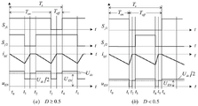
FIG. 9 is a schematic diagram of the main operating waveforms of the capacitor-clamped three-level DC converter with the energy storage circuit charged and the filter inductor current continuously;
FIG. 10 is a schematic diagram of the main operating waveforms of the three-level DC converter with the energy storage circuit charged and the capacitor clamped when the filter inductor current is interrupted;
FIG. 11 is a schematic diagram of the main operating waveforms of the capacitor-clamped three-level DC converter with the energy storage circuit discharging when the filter inductor current is continuous;
FIG. 12 is a schematic diagram of the main operating waveforms of the three-level DC converter with the capacitor clamped and the energy storage circuit discharging when the filter inductor current is interrupted;
FIG. 13 is a schematic diagram of a load dump circuit employing a first capacitor-clamped switching device series chopper topology;
FIG. 14 is a schematic diagram of a load shedding circuit using a second capacitor-clamped switching device series chopper topology;
FIG. 15 is a schematic diagram of a method for controlling the hysteresis of the dump circuit using a capacitor-clamped switching device series chopper topology;
FIG. 16 is a schematic view of the observation of a faulted channel stator flux linkage of the present invention;
FIG. 17 is a schematic diagram of a method for extracting transient DC and negative sequence components of stator flux linkage of a fault channel by using a high-pass filter;
FIG. 18 is a schematic view of a calculation of a reference value of a residual operating channel current command for a multi-phase motor;
fig. 19 is a schematic diagram of the regulation of the remaining operating channel current of a multiphase motor.
Detailed Description
The invention is further illustrated with reference to the following figures and examples:
example 1
Fig. 1 is a general diagram of a control method according to a basic embodiment of the present invention.
A multiphase motor channel fault ride-through operation control method is based on a plurality of converter channels connected with a multiphase motor bridge arm and a winding and comprises overcurrent protection on an alternating current side (namely a motor winding side) of a residual channel inverter, voltage stabilization control on a direct current side of the residual channel inverter and magnetic field compensation control on the multiphase motor by the residual channel inverter in a fault ride-through transition process.
The over-current protection of the alternating current side (namely the motor winding side) of the inverter adopts an active shunt circuit to provide a passage for transient impact surge current, so that the impact surge current flowing through the remaining non-fault channel stator winding is transferred from the bypass of the inverter and is consumed on a current-limiting resistor.
The voltage stabilization control of the direct current side of the inverter adopts a voltage stabilizing circuit to limit the voltage of a direct current bus within a safe and reasonable range, the voltage stabilizing circuit absorbs or releases the energy of the direct current bus through an energy storage circuit, the voltage stabilizing circuit releases overvoltage energy on the direct current bus through a charge releasing circuit, the energy storage circuit adopts a capacitance clamping three-level multiple phase-shifting direct current bidirectional voltage source converter as an energy conversion control interface of the direct current bus and an energy storage medium, and the charge releasing circuit adopts a capacitance clamping type switching device series chopper topology.
And the magnetic field compensation control generates a current space vector with a phase opposite to that of the transient flux linkage of the stator of the fault channel and a corresponding flux linkage component in the residual channel, and counteracts the influence of the transient component of the stator flux linkage of the fault channel on the motor.
And after the system channel fault and the impact suppression attenuation to the motor in the on-line channel switching transition process, the residual channels of the multi-phase motor operate in a fault-tolerant mode.
Example 2
Figure 2 shows a further embodiment of example 1. The difference from example 1 is:
the shunt circuit is an active topology composed of a multiphase (the phase number is the phase number of one channel) full-control power switch device and a current-limiting resistor, and the topology structure can be a multiphase power switch tube such as a bidirectional Insulated Gate Bipolar Transistor (IGBT) anti-parallel bidirectional switch structure. The controller of each channel shunt circuit uses the channel stator winding current i ac As input, if the winding current is lower than the lower safety limit threshold current I of the inverter capacity ac_L The shunt circuit switch tube is blocked, the shunt circuit is closed, the inverter works, and if the winding current is higher than or equal to the upper limit safety threshold current I of the inverter capacity ac_H The shunt circuit is triggered by a switching tube, the shunt circuit is conducted, and all devices in the inverter are turned off at the same time, so that transient surge impact current flows through the current-limiting resistor, and the transient surge current of the winding is accelerated to be attenuated by bypassing the inverter and consuming redundant energy of the winding by using the current-limiting resistor; the shunt circuit adopts a hysteresis mode to determine the on or off of the power switch device. The shunt circuit hysteresis control method is shown in fig. 6.
Furthermore, the topology may be a multi-phase switching tube such as an IGBT common emitter series type bidirectional switching structure as shown in fig. 3, a multi-phase switching tube such as an IGBT parallel-coupled diode bridge type bidirectional switching structure as shown in fig. 4, or a multi-phase diode rectifying switching tube such as an IGBT type structure as shown in fig. 5.
Example 3
Example 3 is a further example of example 1. The difference from example 1 is:
the energy storage circuit is provided with voltage type energy storage media (super capacitors, chemical batteries and the like), and a three-level multiple phase-shifting direct-current bidirectional voltage source converter is used as an energy conversion control interface of a direct-current bus and the energy storage media, so that the voltage and current stress of a switching device are reduced, the ripple wave filtering quality is improved, a filter is reduced, and fault-tolerant operation can be realized.
Example 4
As a further step of embodiment 3, the energy storage circuit uses a capacitor-clamped three-level multiple phase-shift dc bi-directional voltage source converter as an energy conversion control interface between the dc bus and the energy storage medium, so as to reduce the voltage and current stress of the switching device, improve the quality of ripple filtering, reduce the filter, and enable fault-tolerant operation.
The circuit topology is as follows: as shown in fig. 7, the switching tube S j1 、S j2 At node A j Serially connected to form an upper branch bridge arm P j Switching tube S j3 、S j4 At node B j Bridge arm N of lower branch formed by connecting in series j J is the bridge arm number, j is an element [1,k ∈ ]]K is the total number of bridge arms, k is more than or equal to 2, and a node A j And node B j Connecting a clamping capacitor C fj The upper and lower branch bridge arms are at node O j Connected in series to form a complete bridge arm, connected in parallel to a positive and negative DC bus P, N, and connected in parallel to j Connected with a filter current-sharing inductor L pj The other end of the filter current-sharing inductor of each chopping unit is connected with the positive electrode of a voltage type energy storage medium (a super capacitor, a chemical battery and the like) after being connected in parallel at a node E, and the negative electrode of the voltage type energy storage medium is connected to a negative bus N. The switch tube is composed of an anti-parallel diode of a full-control power electronic device.
DC converter implementing DC bus voltage u dc And total current i of the filter current-sharing inductor lp Namely, the double closed-loop control of the current of the energy storage medium, the rapid tracking and the no-difference adjustment are realized through the regulator, and the stability of a direct current link is maintained. DC bus voltage u dc The control loop is an outer loop, and the output amplitude of the direct current bus voltage regulator is limited and then is used as the total current i of the filtering current-sharing inductor lp The reference instruction of (2) defines the total current i of the filter current sharing inductor lp The direction of the signal flowing into the direct current bus, i.e. the direction of the signal flowing out of the energy storage medium, is positive, the absolute value of the output signal of the total current regulator of the filter current sharing inductor is equally divided into reference modulation waves D which are common to all bridge arms of the chopper, as shown in FIG. 8, and ABS is a sign of a function of taking an absolute value. And (3) sequentially staggering the phase of the carrier of each bridge arm by 2 pi/k, so that the phase difference of the on-off time, the voltage and the current of each bridge arm power switch device is 2 pi/k.
And each bridge arm generates the duty ratio of the power switching device according to a capacitance clamping three-level direct current pulse width modulation technology. Total current i of filter current equalizing inductor lp The reference instruction is less than zero, and the converter bridge arm upper branch power switch device S j1 、 S j2 Triggered according to the three-level DC pulse width modulation duty ratio, the lower branch power switch device S j3 、S j4 Blocking, wherein the energy storage circuit absorbs direct current energy; total current i of filter current equalizing inductor lp The reference instruction is larger than zero, and the power switch device S of the lower branch of the bridge arm of the converter j3 、S j4 Modulating duty ratio according to DC three-level DC pulse widthTriggered, upper branch power switching device S j1 、S j2 And (4) blocking, and releasing direct current energy by the energy storage circuit.
The main working waveforms of each operating condition of a single bridge arm of the capacitance-clamped three-level bidirectional direct-current converter are shown in fig. 9-12. In the figure, T s Representing the switching period, T on Represents the on-time, T off The turn-off time is represented by the dotted horizontal line, which is the average value of current and voltage, respectively.
The switching state table of the single bridge arm of the capacitance clamping type bidirectional three-level converter is shown in the following table.


The upper and lower branch bridge arms of the capacitance clamping three-level direct current converter implement voltage-sharing control: and setting the difference value between the voltage of the clamping capacitor and half of the voltage of the direct current bus to be used as a duty ratio correction signal. When the total current reference instruction of the filter current-sharing inductor is less than zero, the switching device S j2 Duty cycle plus correction signal, switching device S j1 The duty cycle minus the correction signal. When the total current reference instruction of the filter current-sharing inductor is greater than zero, the switching device S j3 Duty cycle plus correction signal, switching device S j4 The duty cycle minus the correction signal.
Each heavy bridge arm of the DC converter implements current sharing control: and setting the difference value between the current of each bridge arm and the average current of the bridge arms to be used as a duty ratio correction signal, and conducting a switching tube duty ratio reduction correction signal by each bridge arm.
Example 5
Example 5 is a further example of example 1. The difference from example 1 is:
the load relief circuit is a capacitor-clamped switching device series chopper circuit consisting of a clamping capacitor, a full-control switching tube and an energy consumption resistor, and the first topological form of the load relief circuit is as follows: as shown in fig. 13, branch 1 is formed by a switch tube S 1 And a switching tube S 2 A bridge arm is formed by connecting nodes A in series and serves as an upper branch, and a diode D is arranged on a branch 2 1 And a diode D 2 A bridge arm is formed by connecting the nodes B in series to serve as a lower branch, a switching tube bridge arm of a branch 1 and a diode bridge arm of a branch 2 are connected in series at a point O and then connected to a direct current bus, and the node A, B is connected with a clamping capacitor C in parallel f The load-shedding energy-consuming resistor is connected in parallel with the diode series bridge arm, namely an output connection load-shedding energy-consuming resistor is arranged between the branch node O and the negative bus N. The topological form II is as follows: as shown in fig. 14, branch 1 is formed by a diode D 1 And a diode D 2 The nodes A are connected in series to form a bridge arm as an upper branch, and the branch 2 is formed by a switching tube S 1 And a switching tube S 2 A bridge arm is formed by connecting the nodes B in series to serve as a lower branch, a diode bridge arm of the branch 1 and a switch tube bridge arm of the branch 2 are connected in series at a point O and then connected to a direct current bus, and the node A, B is connected with a clamping capacitor C in parallel f The load-shedding energy-consuming resistor is connected in parallel with the diode series bridge arm, namely an output connection load-shedding energy-consuming resistor is arranged between the branch node O and the positive bus P.
The controllers of the two topology forms of the load relief circuit adopt a hysteresis mode to determine the on or off of a power switch device in the load relief circuit: as shown in fig. 15, the DC bus voltage u is used dc As input, if the DC bus voltage is lower than the lower safety threshold voltage U of the DC link dc_L Switching tube S 1 、S 2 Blocking, closing the charge discharging circuit, and if the voltage of the direct current bus is higher than or equal to the safety upper limit threshold voltage U of the direct current link dc_H Switching tube S 1 、S 2 And the load relief circuit is conducted.
The load relief circuit series switch device adopts a passive device capacitor C f And clamping, namely implementing bridge arm voltage-sharing control and reducing the voltage stress of the power switch device. A topology-type charge-discharging circuit if the clamp capacitor C f The difference value between the voltage and half of the DC bus voltage is higher than the upper limit threshold value, and the switching tube S 1 Blockade, S 2 Conducting if the clamp capacitor C f The difference value between the voltage and half of the DC bus voltage is lower than the lower limit threshold value, and the switching tube S 2 Blockade, S 1 Conducting; a topological type secondary discharging circuit, if the clamping capacitor C f Voltage and DC busThe difference value of half of the voltage is higher than the upper limit threshold value, and the switch tube S 2 Blockade, S 1 Conducting if the clamp capacitor C f The difference value between the voltage and half of the DC bus voltage is lower than the lower limit threshold value, and the switching tube S 1 Blockade, S 2 Conducting; the voltage-sharing control adopts a hysteresis mode to determine the on or off of the power switch device.
Example 6
Example 6 is a further example of example 1.
For a multi-phase motor system with z channels, x channels have faults, the remaining y running channels of the inverter implement motor magnetic field compensation control in the process of faults and on-line channel switching transition, current space vectors in opposite phases with the transient state flux linkages of the stators of the x fault channels and corresponding flux linkage components are generated in the stator windings of the remaining channels through the control of the reference quantity of magnetic field compensation, the influence of the transient state components of the stator flux linkages of the fault channels on the motor is counteracted, and the winding resistance is utilized to finally demagnetize the transient state components of the flux linkages of the windings of the cut channels. And magnetic field compensation control is performed on a rotor magnetic field orientation synchronous rotating coordinate system based on motor rotor magnetic field orientation vector control. Observing stator flux psi of x fault channels x_dq Subscripts alpha and beta respectively represent alpha axis and beta axis parameters of a static coordinate system, subscripts d and q respectively represent d axis and q axis parameters of a fundamental synchronous rotation coordinate system for rotor magnetic field orientation, x represents a fault channel, and y represents the remaining operation channel, and as shown in FIG. 16, stator flux linkage psi is observed in the static coordinate system by a voltage model method x_αβ As shown in the following formula:
ψ x_αβ =∫e x_αβ dt=∫(u x_αβ -R x_αβ i x_αβ )dt
wherein e is x_αβ 、u x_αβ 、i x_αβ Respectively the stator back electromotive force, voltage, current, R of the fault channel in the static coordinate system x_αβ The stator resistance matrix of the fault channel in the static coordinate system.
Then obtaining a fault channel stator flux linkage psi in a rotor magnetic field orientation synchronous rotation coordinate system through conversion from static to rotation coordinates x_dq :
ψ x_dq =Tψ x_αβ
The stationary to synchronous rotating coordinate transformation matrix T is of the form:

the coordinate transformation angle is a phase angle theta between a rotor flux linkage vector and an alpha axis of a static coordinate system r . In a rotor magnetic field directional synchronous rotation coordinate system, positive sequence fundamental wave, transient state direct current and negative sequence components of a fault channel stator flux linkage are respectively characterized as direct current, alternating current with angular frequency of-omega and-2 omega, omega is fundamental wave angular frequency, and high-pass filter technology is adopted to separate and extract transient state direct current and negative sequence components psi of the fault channel stator flux linkage x_dq_dc- As shown in fig. 17, subscripts dc, + and-represent direct current, positive sequence and negative sequence components, respectively;
the high-pass filter is a first-order or second-order filter, respectively having the form:


wherein, ω is c For cutoff angular frequency, ξ is the damping coefficient, with the trade-off between transition bandwidth and frequency sensitivity taken to be between 0.4 and 0.8. Second order filters have narrower transition bandwidths relative to first order filters.
The transient state component of the stator flux linkage of the fault channel is counteracted by the residual channel stator flux linkage, and then the transient state direct current and negative sequence component psi of the stator flux linkage of the fault channel is counteracted x_dq_dc- The negative number of (a) is a given reference for the flux linkage offset compensation quantity of the stator winding of the remaining operation channel, as shown in the following formula:

considering that in the synchronous rotating coordinate system, under the ideal control effect, the flux linkage of the rotor magnetic field in the stator is characterized by the direct current quantity of the fundamental wave, and the flux linkage has no contribution to the transient direct current and negative sequence flux linkage of the stator and the reference setting, wherein the angular frequency of the stator is-omega and-2 omega, and the transient direct current and negative sequence flux linkage of the stator are only generated by the stator current.
Obtaining a given reference value of the residual operation channel stator magnetic field compensation current which is characterized by the alternating current of-omega and-2 omega from the relation between the stator flux linkage and the current

Wherein L is y_dq The equivalent stator excitation inductance matrix is a stator self-inductance matrix.
Residual channel field compensation current reference value Superposed on the given reference value of the original normal operation positive sequence fundamental current
 Obtaining the current of the stator winding of the residual channel and synthesizing a given reference value
 As shown in fig. 18, the following equation:

and the residual channel stator winding current is regulated as a residual operation channel current reference instruction after being subjected to amplitude limiting by a given reference value.
In a rotor magnetic field orientation synchronous rotation coordinate system, characterization of flux linkage and fundamental positive sequence component of currentThe method comprises the steps of giving reference characteristics to direct current quantity, flux linkage and current transient direct current and negative sequence components to alternating current quantity with angular frequency of-omega and-2 omega, providing large enough amplitude gain to a series of direct current and alternating current quantities with positive sequence, direct current and negative sequence components by adopting proportion (P), complex Vector Integral (CVI), multiple (M) second-order vector resonance (generalized integral) (SOVI) regulators, uniformly performing non-static-error accurate decoupling control, and introducing cutoff angular frequency of omega cf The resonance bandwidth coefficient reduces the frequency sensitivity, improves the control robustness and ensures the control precision and the transient performance.
The proportional (P) + Complex Vector Integral (CVI) regulator transfer function is:

where K is the gain coefficient, subscripts p and i denote the proportional and integral coefficients, ω a Is the coupling angular frequency.
The second order vector resonance (generalized integral) (SOVI) regulator transfer function is:

where K is the gain coefficient and the subscript r denotes the resonance coefficient, ω cf Cut-off of angular frequency, omega, for resonance bandwidth x Is the resonant angular frequency.
Then the adjuster is provided with the following form:

in the formula, K is a gain coefficient, subscripts P, i and r respectively represent proportion, integral and resonance coefficients, subscript cf represents a resonance bandwidth cut-off angle frequency coefficient, j represents an imaginary part, the first two terms on the right side of the equation are used, and a P + CVI regulator is used for controlling the stator current fundamental component; third and fourth terms, frequency identification using a second order vector resonance (generalized integral) regulator with an SOVI regulatorSelectively, only the direct current and negative sequence components of the stator current are decoupled and adjusted respectively and are characterized as negative sequence primary harmonic components and negative sequence secondary harmonic components respectively in a synchronous rotating coordinate system, namely the resonant angular frequency omega of the SOVI regulator is made x Respectively-omega and-2 omega. Omega a For coupling angular frequencies, when the control motor is an induction motor, ω a Is the angular frequency omega of the rotation difference s When the control motor is a synchronous motor, ω a Is the synchronous angular frequency omega. The remaining operating channel current regulation is shown in fig. 19. The remaining operating channel stator current regulator output is a remaining operating channel stator voltage reference Obtaining the reference specification of a static coordinate system through conversion from rotation to static coordinate

The transformation matrix T-1 for synchronous rotation to stationary coordinates is of the form:

the coordinate transformation angle is the phase angle theta between the rotor flux linkage vector and the alpha axis of the stationary coordinate system r . And then, the space voltage vector modulation (SVPWM) is used for obtaining the duty ratio of each power switching device of the inverter of the rest operation channel and driving the power switching devices of the inverter of the rest operation channel.
Although the present invention has been described with reference to the accompanying drawings, the present invention is not limited to the above embodiments, which are only illustrative and not restrictive, and those skilled in the art can make many modifications without departing from the spirit and scope of the present invention as defined in the appended claims.
Claims (5)
1. A multiphase motor channel fault ride-through operation control method is based on a plurality of converter channels connected with a multiphase motor winding, each converter channel comprises a load relief circuit and an energy storage circuit, and the method is characterized in that: the method comprises the steps of overcurrent protection on the alternating current side of a non-fault channel inverter, voltage stabilization control on the direct current side of the non-fault channel inverter and magnetic field compensation control on a multi-phase motor by the non-fault channel inverter in the fault ride-through transition process;
the over-current protection of the alternating current side of the inverter adopts an active shunt circuit to provide a passage for transient impact surge current, so that the impact surge current flowing through the stator winding of the residual non-fault channel is transferred from the bypass of the inverter and is consumed on a current-limiting resistor;
the energy storage circuit is provided with a voltage type energy storage medium, a three-level multiple phase-shift direct-current bidirectional voltage source converter is used as an energy conversion control interface of a direct-current bus and the energy storage medium, and the load shedding circuit adopts a chopper topology;
the three-level multiple phase-shift direct-current bidirectional voltage source converter is a capacitance clamping three-level multiple phase-shift direct-current bidirectional voltage source converter, and the circuit topology is as follows: switch tube S j1 、S j2 At node A j Upper branch bridge arm P formed by series connection j Switching tube S j3 、S j4 At node B j Bridge arm N of lower branch formed by connecting in series j J is the bridge arm number, j is an element [1,k ∈ ]]K is the total number of bridge arms, k is more than or equal to 2, and a node A j And node B j Connecting a clamping capacitor C fj The upper and lower branch bridge arms are at node O j Connected in series to form a complete bridge arm, connected in parallel to a positive and negative DC bus P, N, and connected in parallel to j Connected with a filter current-sharing inductor L pj The other ends of the filtering and current-sharing inductors of all the chopping units are connected with the positive electrode of a voltage-type energy storage medium after being connected in parallel at a node E, and the negative electrode of the voltage-type energy storage medium is connected to a negative bus N; the switch tube is composed of a full-control power switch device and an anti-parallel diode; capacitance clamping three-level multi-phase-shift direct-current bidirectional voltage source transformerConverter implementing dc bus voltage u dc And total current i of the filter current-sharing inductor lp Namely, the double closed-loop control of the current of the energy storage medium, the rapid tracking and the no-difference adjustment are realized through the regulator, and the stability of a direct current link is maintained; DC bus voltage u dc The control loop is an outer loop, and the output amplitude of the direct current bus voltage regulator is limited and then is used as the total current i of the filtering current-sharing inductor lp The reference instruction of (2) defines the total current i of the filtering current sharing inductor lp The direction of the direct current flowing into the direct current bus, namely the direction of the direct current flowing out of the energy storage medium is positive, the absolute value of an output signal of the filter inductor total current regulator is uniformly divided into reference modulation waves D which are common to all bridge arms of the chopper, the phases of the carrier waves of all the bridge arms are sequentially staggered by 2 pi/k, and the phase difference of the on-off time, the voltage and the current of the power switch device of each bridge arm is 2 pi/k; each bridge arm generates the duty ratio of a power switch device according to a capacitance clamping three-level direct current pulse width modulation technology, and filters the total current i of a current-sharing inductor lp The reference instruction is less than zero, and the converter bridge arm upper branch power switch device S j1 、S j2 Triggered according to three-level direct current pulse width modulation duty ratio and lower branch power switching device S j3 、S j4 Blocking, wherein the energy storage circuit absorbs direct current energy; total current i of filter current equalizing inductor lp The reference instruction is larger than zero, and the power switch device S of the lower branch of the bridge arm of the converter j3 、S j4 Triggered according to the duty ratio of DC three-level DC pulse width modulation, the power switch device S of the upper branch j1 、S j2 Blocking, the energy storage circuit releases direct current energy; the capacitor clamping three-level multiple phase-shifting direct-current bidirectional voltage source converter bridge arm implements voltage-sharing control: setting the difference value between the voltage of the clamping capacitor and half of the voltage of the direct current bus to be used as a duty ratio correction signal; when the total current reference instruction of the filter current-sharing inductor is less than zero, the switching device S j2 Duty cycle plus correction signal, switching device S j1 A duty cycle minus correction signal; when the total current reference instruction of the filter current-sharing inductor is greater than zero, the switching device S j3 Duty cycle plus correction signal, switching device S j4 A duty cycle minus correction signal; each heavy bridge arm of the capacitance clamping three-level multiple phase-shifting direct-current bidirectional voltage source converter implements current sharing control: setting the difference value of each bridge arm current and the average bridge arm current to obtain the difference valueThe duty ratio correction signal is used for reducing the duty ratio of each bridge arm conducting switching tube;
the magnetic field compensation control generates a current space vector and a corresponding flux linkage component in a phase opposite to that of a fault channel stator transient flux linkage in a non-fault channel, and counteracts the influence of the transient component of the fault channel stator flux linkage on the motor;
and after the system channel fails and the impact on the motor is restrained and attenuated in the on-line channel switching transition process, the multi-phase motor operates in a fault-tolerant mode through a non-failure channel.
2. The method according to claim 1, wherein the shunt circuit is an active topology composed of a multiphase fully-controlled power switch device and a current-limiting resistor, and adopts an anti-parallel type bidirectional switch structure of multiphase power switch tubes, or a series type bidirectional switch structure of common emitters of multiphase switch tubes, or a parallel type bidirectional switch structure of diode bridge type of multiphase switch tubes, or a type structure of multiphase diode rectifying and connecting switch tubes; the controller of each channel shunt circuit uses the channel stator winding current i ac As input, if the winding current is lower than the lower limit safety threshold current of the inverter capacity, the shunt circuit switch tube is blocked, the shunt circuit is closed, the inverter works, if the winding current is higher than or equal to the upper limit safety threshold current of the inverter capacity, the shunt circuit switch tube is triggered, the shunt circuit is conducted, and simultaneously all devices in the inverter are turned off, so that transient surge impact current flows through the current limiting resistor, and the inverter is bypassed, and the transient surge current of the winding is attenuated by using the current limiting resistor to consume redundant energy of the winding; the shunt circuit adopts a hysteresis mode to determine the on or off of the power switch device.
3. The method for controlling the path fault ride-through operation of the multiphase motor according to claim 1, wherein the load shedding circuit topology is as follows: branch 1 is composed of a switch tube S 1 And a switching tube S 2 A bridge arm is formed by connecting nodes A in series and serves as an upper branch, and a diode D is arranged on a branch 2 1 And a diode D 2 Are connected in series at the node B to form a bridge arm as a lower branchThe circuit 1 switching tube bridge arm and the branch circuit 2 diode bridge arm are connected in series at the point O and then connected to a direct current bus, and the node A, B is connected in parallel with a clamping capacitor C f The load-shedding energy-consuming resistor is connected in parallel with the diode series bridge arm, namely an output connection load-shedding energy-consuming resistor is arranged between the branch node O and the negative bus N; the controller of the load relief circuit adopts a hysteresis mode to determine the on or off of a power switch device in the load relief circuit: with DC bus voltage u dc As input, if the DC bus voltage is lower than the threshold voltage of the DC link safety lower limit, the switch tube S 1 、S 2 Blocking, closing the charge discharging circuit, and switching on or off the switch tube S if the voltage of the DC bus is higher than or equal to the upper safety limit threshold voltage of the DC link 1 、S 2 Conducting, and conducting the load relief circuit; the load relief circuit series switch device adopts a passive device capacitor C f Clamping, implementing bridge arm voltage-sharing control, reducing voltage stress of power switch device, if clamping capacitor C f The difference value between the voltage and half of the DC bus voltage is higher than the upper limit threshold value, and the switching tube S 1 Blockade, S 2 Conducting if the clamp capacitor C f The difference value between the voltage and half of the DC bus voltage is lower than the lower limit threshold value, and the switching tube S 2 Blockade, S 1 Conducting; the voltage-sharing control adopts a hysteresis mode to determine the on or off of the power switch device.
4. A multiphase motor path fault ride-through operation control method as recited in claim 3, wherein the load shedding circuit topology is as follows: branch 1 is formed by a diode D 1 And a diode D 2 The nodes A are connected in series to form a bridge arm as an upper branch, and the branch 2 is formed by a switching tube S 1 And a switching tube S 2 A bridge arm is formed by connecting the nodes B in series to serve as a lower branch, a diode bridge arm of the branch 1 and a switch tube bridge arm of the branch 2 are connected in series at a point O and then connected to a direct current bus, and the node A, B is connected with a clamping capacitor C in parallel f The load-shedding energy-consuming resistor is connected in parallel with the diode series bridge arm, namely an output connection load-shedding energy-consuming resistor is arranged between the branch node O and the positive bus P; the controller of the load relief circuit adopts a hysteresis mode to determine the on or off of a power switch device in the load relief circuit: with DC bus voltage u dc As an input, ifThe DC bus voltage is lower than the lower limit threshold voltage of the DC link safety, and the switch tube S 1 、S 2 Blocking, closing the unloading circuit, and switching on or off the switch tube S if the voltage of the DC bus is higher than or equal to the upper limit of the DC link safety threshold voltage 1 、S 2 Conducting, and conducting the load relief circuit; the load relief circuit series switch device adopts a passive device capacitor C f Clamping, implementing bridge arm voltage-sharing control, reducing voltage stress of power switch device, if clamping capacitor C f The difference value between the voltage and half of the direct current bus voltage is higher than the upper limit threshold value, and the switch tube S 2 Blockade, S 1 Conducting if the clamp capacitor C f The difference value between the voltage and half of the DC bus voltage is lower than the lower limit threshold value, and the switching tube S 1 Blockade, S 2 Conducting; the voltage-sharing control adopts a hysteresis mode to determine the on or off of the power switch device.
5. The method according to claim 1, wherein for a z-channel multiphase motor system, x channels are failed, and the remaining y channels of the inverter perform motor field compensation control during the fault and on-line channel switching transition, and by controlling the reference quantity of the field compensation, current space vectors and corresponding flux linkage components in opposite phases with the transient flux linkages of the x stator channels are generated in the stator windings of the non-fault channels, so as to counteract the influence of the transient components of the stator flux linkages of the fault channels on the motor; observing stator flux linkage psi of x fault channels x_dq Subscripts d and q respectively represent parameters of a d axis and a q axis of a fundamental wave synchronous rotating coordinate system of rotor magnetic field orientation, positive sequence fundamental wave, transient direct current and negative sequence components of a stator flux linkage of a fault channel are respectively characterized by direct current quantity and alternating current quantity with angular frequency of-omega and-2 omega, omega is fundamental wave angular frequency, and a high-pass filter technology is adopted to separate and extract transient direct current and negative sequence components psi of the stator flux linkage of the fault channel x_dq_dc- Subscripts dc, + and-represent direct current, positive sequence and negative sequence components, respectively;
the high-pass filter is a first-order or second-order filter, respectively having the form:


wherein, ω is c For cutoff angular frequency, ξ is the damping coefficient, the second order filter has a narrower transition bandwidth than the first order filter;
the transient direct current and negative sequence component psi of the stator flux linkage of the fault channel is obtained by offsetting the transient component of the stator flux linkage of the fault channel by the residual non-fault channel stator flux linkage x_dq_dc- The negative number of (a) is a given reference for the flux linkage offset compensation quantity of the stator winding of the remaining operation channel, as shown in the following formula:

obtaining a given reference value of the stator magnetic field compensation current of the residual operation channel characterized by the alternating current of-omega and-2 omega of angular frequency according to the relation between the stator flux linkage and the current

Wherein L is y_dq Equivalent stator excitation inductance matrixes of the rest channels are stator self-inductance matrixes;
the residual channel magnetic field compensation current reference value is superposed on the original normal operation positive sequence fundamental wave current given reference value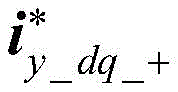 Obtaining a residual channel stator winding current synthesis given reference value:

the residual channel stator winding current is regulated as a residual operation channel current reference instruction after being subjected to amplitude limiting by a given reference value;
in a rotor magnetic field directional synchronous rotating coordinate system, a fundamental wave positive sequence component of a magnetic linkage and a current is characterized as a direct current quantity, a magnetic linkage and current transient direct current and negative sequence component are given reference and characterized as alternating current quantities with angular frequencies of-omega and-2 omega, a proportion, complex vector integration and a second-order vector resonance regulator are adopted to provide a large enough amplitude gain for a series of direct current and alternating current quantities with positive sequence, direct current and negative sequence component characterization, static error-free accurate decoupling control is uniformly carried out, and a cutoff angular frequency of omega is introduced cf The resonance bandwidth coefficient reduces the frequency sensitivity, improves the control robustness and ensures the control precision and the transient performance;
the adopted regulator has the following form:

in the formula, K is a gain coefficient, subscripts p, i and r respectively represent proportion, integration and resonance coefficients, subscript cf represents a resonance bandwidth cut-off angle frequency coefficient, the first two terms on the right side of the equation are used for controlling a stator current fundamental component by adopting a proportion + complex vector integral regulator; the third and the fourth terms respectively adopt a second-order vector resonance regulator, only respectively decouple and regulate the direct current and negative sequence components of the stator current by utilizing the frequency identification selectivity of the second-order vector resonance regulator, and respectively represent the direct current and negative sequence secondary harmonic components, omega, of the negative sequence in a synchronous rotating coordinate system a For coupling angular frequencies, when the control motor is an induction motor, ω a Is the angular frequency omega of the rotation difference s When the control motor is a synchronous motor, ω a Is the synchronous angular frequency omega.
Priority Applications (1)
| Application Number | Priority Date | Filing Date | Title |
|---|---|---|---|
| CN201811651809.5A CN109802483B (en) | 2018-12-31 | 2018-12-31 | Multiphase motor channel fault ride-through operation control method |
Applications Claiming Priority (1)
| Application Number | Priority Date | Filing Date | Title |
|---|---|---|---|
| CN201811651809.5A CN109802483B (en) | 2018-12-31 | 2018-12-31 | Multiphase motor channel fault ride-through operation control method |
Publications (2)
| Publication Number | Publication Date |
|---|---|
| CN109802483A CN109802483A (en) | 2019-05-24 |
| CN109802483B true CN109802483B (en) | 2022-11-15 |
Family
ID=66556830
Family Applications (1)
| Application Number | Title | Priority Date | Filing Date |
|---|---|---|---|
| CN201811651809.5A Active CN109802483B (en) | 2018-12-31 | 2018-12-31 | Multiphase motor channel fault ride-through operation control method |
Country Status (1)
| Country | Link |
|---|---|
| CN (1) | CN109802483B (en) |
Families Citing this family (10)
| Publication number | Priority date | Publication date | Assignee | Title |
|---|---|---|---|---|
| CN110797910B (en) * | 2019-10-28 | 2023-06-02 | 天津大学 | A Control Method for Improving Low Voltage Ride Through Capability of Matrix Converter System |
| CN110768559B (en) * | 2019-11-12 | 2021-10-01 | 上海电气富士电机电气技术有限公司 | System and method for generating flat-top wave for sinusoidal pulse width modulation |
| CN111600328A (en) * | 2020-05-29 | 2020-08-28 | 特变电工西安柔性输配电有限公司 | Power balancing device and control method for flexible and direct delivery system of new energy |
| US11325714B2 (en) * | 2020-07-09 | 2022-05-10 | General Electric Company | Electric power system for a vehicle |
| CN113972824B (en) * | 2020-07-22 | 2023-12-15 | 广东美的制冷设备有限公司 | Totem pole PFC circuit, control method, circuit board and air conditioner |
| CN113972827B (en) * | 2020-07-22 | 2024-04-26 | 广东美的制冷设备有限公司 | Totem pole PFC circuit and control method thereof, circuit board, air conditioner, and storage medium |
| CN112100945B (en) * | 2020-08-05 | 2023-12-26 | 苏州汇川联合动力系统股份有限公司 | Short circuit to ground detection method, motor controller and computer-readable storage medium |
| CN113178845B (en) * | 2021-04-25 | 2023-03-31 | 哈尔滨旋驰电气科技有限公司 | Alternating current power supply phase number conversion method and device |
| CN118487508A (en) * | 2024-07-09 | 2024-08-13 | 湖南大学 | Single-phase multi-level inverter with boosted alternating current side |
| CN120709931A (en) * | 2025-08-11 | 2025-09-26 | 天津大学 | A large-capacity compact DC conversion switch and control method |
Citations (3)
| Publication number | Priority date | Publication date | Assignee | Title |
|---|---|---|---|---|
| CN103078339A (en) * | 2013-01-29 | 2013-05-01 | 武汉大学 | Low-voltage ride through control system and method for capacity-optimal energy-storage type double-fed motor |
| CN104967384A (en) * | 2015-07-07 | 2015-10-07 | 河南师范大学 | Synchronous flux weakening control method for stator and rotor flux linkage of doubly-fed wind turbine under grid fault |
| CN106842987A (en) * | 2017-02-26 | 2017-06-13 | 上海交通大学 | The electromechanical transient modeling method of direct-driving type wind power generation unit |
-
2018
- 2018-12-31 CN CN201811651809.5A patent/CN109802483B/en active Active
Patent Citations (3)
| Publication number | Priority date | Publication date | Assignee | Title |
|---|---|---|---|---|
| CN103078339A (en) * | 2013-01-29 | 2013-05-01 | 武汉大学 | Low-voltage ride through control system and method for capacity-optimal energy-storage type double-fed motor |
| CN104967384A (en) * | 2015-07-07 | 2015-10-07 | 河南师范大学 | Synchronous flux weakening control method for stator and rotor flux linkage of doubly-fed wind turbine under grid fault |
| CN106842987A (en) * | 2017-02-26 | 2017-06-13 | 上海交通大学 | The electromechanical transient modeling method of direct-driving type wind power generation unit |
Also Published As
| Publication number | Publication date |
|---|---|
| CN109802483A (en) | 2019-05-24 |
Similar Documents
| Publication | Publication Date | Title |
|---|---|---|
| CN109802483B (en) | Multiphase motor channel fault ride-through operation control method | |
| CN109639214B (en) | Multiphase motor fault-tolerant on-line channel-cutting transition process control method | |
| Aboelsaud et al. | Review of three-phase inverters control for unbalanced load compensation | |
| CN100505469C (en) | Flexible AC double-feed type wind generating and transmitting system | |
| Xu et al. | The modular current-fed high-frequency isolated matrix converters for wind energy conversion | |
| CN102214924B (en) | Feedforward decoupling control method of three-level active power quality compensator based on three-phase two-arm | |
| CN106329979B (en) | A MMC dual loop current suppression method for high-speed permanent magnet motor system | |
| CN102064533A (en) | Direct-current overvoltage control system of uncontrollable rectification unit of cascade high-voltage transducer | |
| CN106385214B (en) | High-speed permanent magnetic synchronous motor control method based on Modular multilevel converter | |
| CN104218585A (en) | Active power filter with power unit and control method thereof | |
| CN110233496A (en) | The control method of tandem photovoltaic solid-state transformer under the conditions of unbalanced source voltage | |
| CN111277157A (en) | Modular high-power motor driving converter system and control method | |
| Sun et al. | Quasi-Z-source-fed SRM drive for torque ripple minimization and speed range extension with three-switch conduction | |
| CN116632902A (en) | A Multi-port Flexible DC Transmission System Based on PWM Current Source Converter | |
| Deng et al. | A furtherance of high-power adjustable-speed drive systems: Medium-frequency ac link-powered machine drive systems | |
| CN110224622A (en) | Bridge-type modular multi-level converter submodule capacitor voltage fluctuates suppressing method | |
| Tesaki et al. | Control and experimental verification of a bidirectional non-isolated dc-dc converter based on three-level flying-capacitor converters | |
| Shi et al. | The application of active superconducting DC fault current limiter in hybrid AC/DC power supply systems | |
| Wang et al. | DC-link current optimal control of current source converter in DFIG | |
| CN120855491A (en) | A new four-level high-efficiency grid-connected system and control method | |
| CN110729717B (en) | A Traction Compensation System with Double Full-Bridge Back-to-Back Converters Parallel | |
| CN104218586A (en) | Power unit of active power filter and control method of power unit | |
| CN201041943Y (en) | Flexible AC double-fed wind power transmission system | |
| CN112564121A (en) | Topology reconstruction and function multiplexing oriented series-connection type power electronic equipment and control method | |
| Kumar et al. | Fault-tolerant grid-connected single to three-phase multilevel converter for induction motor drive |
Legal Events
| Date | Code | Title | Description |
|---|---|---|---|
| PB01 | Publication | ||
| PB01 | Publication | ||
| SE01 | Entry into force of request for substantive examination | ||
| SE01 | Entry into force of request for substantive examination | ||
| GR01 | Patent grant | ||
| GR01 | Patent grant |