CN109884184B - Device for assessing haemostasis - Google Patents
Device for assessing haemostasis Download PDFInfo
- Publication number
- CN109884184B CN109884184B CN201910203968.7A CN201910203968A CN109884184B CN 109884184 B CN109884184 B CN 109884184B CN 201910203968 A CN201910203968 A CN 201910203968A CN 109884184 B CN109884184 B CN 109884184B
- Authority
- CN
- China
- Prior art keywords
- test
- chamber
- sample
- modulus
- resonance
- Prior art date
- Legal status (The legal status is an assumption and is not a legal conclusion. Google has not performed a legal analysis and makes no representation as to the accuracy of the status listed.)
- Active
Links
- 230000023597 hemostasis Effects 0.000 title claims abstract description 15
- 238000012360 testing method Methods 0.000 claims abstract description 107
- 239000003153 chemical reaction reagent Substances 0.000 claims abstract description 7
- 238000009534 blood test Methods 0.000 claims abstract 6
- 238000006073 displacement reaction Methods 0.000 claims description 124
- 238000002604 ultrasonography Methods 0.000 claims description 39
- 230000005855 radiation Effects 0.000 claims description 38
- 238000005259 measurement Methods 0.000 claims description 37
- 210000004369 blood Anatomy 0.000 claims description 36
- 239000008280 blood Substances 0.000 claims description 36
- 230000015271 coagulation Effects 0.000 claims description 28
- 238000005345 coagulation Methods 0.000 claims description 28
- 238000003556 assay Methods 0.000 claims description 9
- 208000007536 Thrombosis Diseases 0.000 claims description 6
- 230000005540 biological transmission Effects 0.000 claims description 6
- 239000007822 coupling agent Substances 0.000 claims description 5
- 102000015081 Blood Coagulation Factors Human genes 0.000 claims description 4
- 108010039209 Blood Coagulation Factors Proteins 0.000 claims description 4
- 102000009123 Fibrin Human genes 0.000 claims description 4
- 108010073385 Fibrin Proteins 0.000 claims description 4
- BWGVNKXGVNDBDI-UHFFFAOYSA-N Fibrin monomer Chemical compound CNC(=O)CNC(=O)CN BWGVNKXGVNDBDI-UHFFFAOYSA-N 0.000 claims description 4
- 239000003114 blood coagulation factor Substances 0.000 claims description 4
- 229950003499 fibrin Drugs 0.000 claims description 4
- 238000010521 absorption reaction Methods 0.000 claims description 3
- 230000015572 biosynthetic process Effects 0.000 claims description 3
- 230000000977 initiatory effect Effects 0.000 claims description 2
- 230000009089 cytolysis Effects 0.000 claims 1
- 230000001105 regulatory effect Effects 0.000 claims 1
- 239000000523 sample Substances 0.000 description 97
- 238000000034 method Methods 0.000 description 48
- 230000033001 locomotion Effects 0.000 description 32
- 230000010355 oscillation Effects 0.000 description 29
- 239000000243 solution Substances 0.000 description 21
- 238000005094 computer simulation Methods 0.000 description 19
- 230000014509 gene expression Effects 0.000 description 18
- 230000006870 function Effects 0.000 description 17
- 238000002592 echocardiography Methods 0.000 description 16
- 239000000463 material Substances 0.000 description 16
- 230000000694 effects Effects 0.000 description 15
- 230000035602 clotting Effects 0.000 description 14
- 238000004458 analytical method Methods 0.000 description 11
- 239000007788 liquid Substances 0.000 description 11
- 230000008569 process Effects 0.000 description 11
- 206010053567 Coagulopathies Diseases 0.000 description 10
- 238000004422 calculation algorithm Methods 0.000 description 10
- 230000007246 mechanism Effects 0.000 description 10
- 238000013459 approach Methods 0.000 description 8
- 238000012545 processing Methods 0.000 description 8
- 230000008859 change Effects 0.000 description 7
- 210000002381 plasma Anatomy 0.000 description 7
- 230000008901 benefit Effects 0.000 description 6
- 238000004364 calculation method Methods 0.000 description 6
- 230000007704 transition Effects 0.000 description 6
- 235000013351 cheese Nutrition 0.000 description 5
- 230000000875 corresponding effect Effects 0.000 description 5
- 238000001514 detection method Methods 0.000 description 5
- 238000001914 filtration Methods 0.000 description 5
- 230000010363 phase shift Effects 0.000 description 5
- 230000002829 reductive effect Effects 0.000 description 5
- 230000006399 behavior Effects 0.000 description 4
- 210000004027 cell Anatomy 0.000 description 4
- 238000011156 evaluation Methods 0.000 description 4
- 230000000873 masking effect Effects 0.000 description 4
- 230000036961 partial effect Effects 0.000 description 4
- 230000001902 propagating effect Effects 0.000 description 4
- 230000009467 reduction Effects 0.000 description 4
- 238000005070 sampling Methods 0.000 description 4
- 239000007787 solid Substances 0.000 description 4
- 208000032843 Hemorrhage Diseases 0.000 description 3
- 239000004793 Polystyrene Substances 0.000 description 3
- 208000034158 bleeding Diseases 0.000 description 3
- 230000000740 bleeding effect Effects 0.000 description 3
- 238000012512 characterization method Methods 0.000 description 3
- 238000013016 damping Methods 0.000 description 3
- 238000010586 diagram Methods 0.000 description 3
- 235000013305 food Nutrition 0.000 description 3
- 230000002439 hemostatic effect Effects 0.000 description 3
- 238000003384 imaging method Methods 0.000 description 3
- 230000003993 interaction Effects 0.000 description 3
- 230000004048 modification Effects 0.000 description 3
- 238000012986 modification Methods 0.000 description 3
- 230000003534 oscillatory effect Effects 0.000 description 3
- 229920002223 polystyrene Polymers 0.000 description 3
- 230000035945 sensitivity Effects 0.000 description 3
- 230000003068 static effect Effects 0.000 description 3
- 229920001169 thermoplastic Polymers 0.000 description 3
- 239000004416 thermosoftening plastic Substances 0.000 description 3
- 239000005995 Aluminium silicate Substances 0.000 description 2
- 102000008946 Fibrinogen Human genes 0.000 description 2
- 108010049003 Fibrinogen Proteins 0.000 description 2
- 230000003044 adaptive effect Effects 0.000 description 2
- 230000032683 aging Effects 0.000 description 2
- 239000003570 air Substances 0.000 description 2
- 235000012211 aluminium silicate Nutrition 0.000 description 2
- 230000017531 blood circulation Effects 0.000 description 2
- 238000005314 correlation function Methods 0.000 description 2
- 230000001934 delay Effects 0.000 description 2
- 230000001419 dependent effect Effects 0.000 description 2
- 238000002474 experimental method Methods 0.000 description 2
- 229940012952 fibrinogen Drugs 0.000 description 2
- 238000010438 heat treatment Methods 0.000 description 2
- 230000006872 improvement Effects 0.000 description 2
- 239000012535 impurity Substances 0.000 description 2
- 230000001939 inductive effect Effects 0.000 description 2
- 208000014674 injury Diseases 0.000 description 2
- NLYAJNPCOHFWQQ-UHFFFAOYSA-N kaolin Chemical compound O.O.O=[Al]O[Si](=O)O[Si](=O)O[Al]=O NLYAJNPCOHFWQQ-UHFFFAOYSA-N 0.000 description 2
- 238000004519 manufacturing process Methods 0.000 description 2
- 238000013442 quality metrics Methods 0.000 description 2
- 238000011160 research Methods 0.000 description 2
- 230000004044 response Effects 0.000 description 2
- 238000012552 review Methods 0.000 description 2
- 239000000758 substrate Substances 0.000 description 2
- 210000001519 tissue Anatomy 0.000 description 2
- XLYOFNOQVPJJNP-UHFFFAOYSA-N water Substances O XLYOFNOQVPJJNP-UHFFFAOYSA-N 0.000 description 2
- 241001502871 Apallaga kasai Species 0.000 description 1
- 102100026816 DNA-dependent metalloprotease SPRTN Human genes 0.000 description 1
- 101710175461 DNA-dependent metalloprotease SPRTN Proteins 0.000 description 1
- 102000004190 Enzymes Human genes 0.000 description 1
- 108090000790 Enzymes Proteins 0.000 description 1
- 102000016359 Fibronectins Human genes 0.000 description 1
- 108010067306 Fibronectins Proteins 0.000 description 1
- 206010028980 Neoplasm Diseases 0.000 description 1
- 235000017284 Pometia pinnata Nutrition 0.000 description 1
- 240000007653 Pometia tomentosa Species 0.000 description 1
- 206010051077 Post procedural haemorrhage Diseases 0.000 description 1
- 238000012952 Resampling Methods 0.000 description 1
- 206010040047 Sepsis Diseases 0.000 description 1
- 208000006011 Stroke Diseases 0.000 description 1
- 230000009471 action Effects 0.000 description 1
- 230000004931 aggregating effect Effects 0.000 description 1
- XAGFODPZIPBFFR-UHFFFAOYSA-N aluminium Chemical group [Al] XAGFODPZIPBFFR-UHFFFAOYSA-N 0.000 description 1
- 229910052782 aluminium Inorganic materials 0.000 description 1
- 239000012080 ambient air Substances 0.000 description 1
- 239000003146 anticoagulant agent Substances 0.000 description 1
- 229940127219 anticoagulant drug Drugs 0.000 description 1
- 239000011324 bead Substances 0.000 description 1
- 238000005422 blasting Methods 0.000 description 1
- 230000000903 blocking effect Effects 0.000 description 1
- 230000023555 blood coagulation Effects 0.000 description 1
- 201000011510 cancer Diseases 0.000 description 1
- 230000000747 cardiac effect Effects 0.000 description 1
- 238000007675 cardiac surgery Methods 0.000 description 1
- 238000006243 chemical reaction Methods 0.000 description 1
- 239000003795 chemical substances by application Substances 0.000 description 1
- 239000002131 composite material Substances 0.000 description 1
- 230000006835 compression Effects 0.000 description 1
- 238000007906 compression Methods 0.000 description 1
- 230000001010 compromised effect Effects 0.000 description 1
- 238000012790 confirmation Methods 0.000 description 1
- 239000000470 constituent Substances 0.000 description 1
- 230000001276 controlling effect Effects 0.000 description 1
- 238000001816 cooling Methods 0.000 description 1
- 230000002596 correlated effect Effects 0.000 description 1
- 239000013078 crystal Substances 0.000 description 1
- 230000001186 cumulative effect Effects 0.000 description 1
- 230000006378 damage Effects 0.000 description 1
- 238000007405 data analysis Methods 0.000 description 1
- 238000009795 derivation Methods 0.000 description 1
- 238000013461 design Methods 0.000 description 1
- 238000011161 development Methods 0.000 description 1
- 230000018109 developmental process Effects 0.000 description 1
- 230000004064 dysfunction Effects 0.000 description 1
- 230000008030 elimination Effects 0.000 description 1
- 238000003379 elimination reaction Methods 0.000 description 1
- 238000005516 engineering process Methods 0.000 description 1
- 210000003743 erythrocyte Anatomy 0.000 description 1
- 210000002744 extracellular matrix Anatomy 0.000 description 1
- 239000000535 fibrinogen concentrate Substances 0.000 description 1
- 239000003527 fibrinolytic agent Substances 0.000 description 1
- 230000003480 fibrinolytic effect Effects 0.000 description 1
- 239000012530 fluid Substances 0.000 description 1
- 239000002778 food additive Substances 0.000 description 1
- 235000013373 food additive Nutrition 0.000 description 1
- 239000004023 fresh frozen plasma Substances 0.000 description 1
- 208000019622 heart disease Diseases 0.000 description 1
- 230000006881 hemostatic dysfunction Effects 0.000 description 1
- 238000013383 initial experiment Methods 0.000 description 1
- 238000002347 injection Methods 0.000 description 1
- 239000007924 injection Substances 0.000 description 1
- 230000001788 irregular Effects 0.000 description 1
- 230000000670 limiting effect Effects 0.000 description 1
- 238000000691 measurement method Methods 0.000 description 1
- 239000004005 microsphere Substances 0.000 description 1
- 230000007935 neutral effect Effects 0.000 description 1
- 235000015097 nutrients Nutrition 0.000 description 1
- 239000002245 particle Substances 0.000 description 1
- 238000000059 patterning Methods 0.000 description 1
- 230000035790 physiological processes and functions Effects 0.000 description 1
- 238000012123 point-of-care testing Methods 0.000 description 1
- 229920000642 polymer Polymers 0.000 description 1
- 102000004169 proteins and genes Human genes 0.000 description 1
- 108090000623 proteins and genes Proteins 0.000 description 1
- 230000003252 repetitive effect Effects 0.000 description 1
- 238000007788 roughening Methods 0.000 description 1
- 210000002966 serum Anatomy 0.000 description 1
- 230000003595 spectral effect Effects 0.000 description 1
- 238000001228 spectrum Methods 0.000 description 1
- 238000003860 storage Methods 0.000 description 1
- 230000035882 stress Effects 0.000 description 1
- 239000000126 substance Substances 0.000 description 1
- 238000001356 surgical procedure Methods 0.000 description 1
- 238000002560 therapeutic procedure Methods 0.000 description 1
- 239000003634 thrombocyte concentrate Substances 0.000 description 1
- 230000036962 time dependent Effects 0.000 description 1
- 238000013334 tissue model Methods 0.000 description 1
- 238000012546 transfer Methods 0.000 description 1
- 230000008733 trauma Effects 0.000 description 1
- 230000008736 traumatic injury Effects 0.000 description 1
- 238000002525 ultrasonication Methods 0.000 description 1
- 238000012285 ultrasound imaging Methods 0.000 description 1
- 239000003190 viscoelastic substance Substances 0.000 description 1
Images


Classifications
-
- G—PHYSICS
- G01—MEASURING; TESTING
- G01N—INVESTIGATING OR ANALYSING MATERIALS BY DETERMINING THEIR CHEMICAL OR PHYSICAL PROPERTIES
- G01N29/00—Investigating or analysing materials by the use of ultrasonic, sonic or infrasonic waves; Visualisation of the interior of objects by transmitting ultrasonic or sonic waves through the object
- G01N29/44—Processing the detected response signal, e.g. electronic circuits specially adapted therefor
- G01N29/4409—Processing the detected response signal, e.g. electronic circuits specially adapted therefor by comparison
- G01N29/4418—Processing the detected response signal, e.g. electronic circuits specially adapted therefor by comparison with a model, e.g. best-fit, regression analysis
-
- A—HUMAN NECESSITIES
- A61—MEDICAL OR VETERINARY SCIENCE; HYGIENE
- A61B—DIAGNOSIS; SURGERY; IDENTIFICATION
- A61B8/00—Diagnosis using ultrasonic, sonic or infrasonic waves
- A61B8/08—Clinical applications
- A61B8/0883—Clinical applications for diagnosis of the heart
-
- A—HUMAN NECESSITIES
- A61—MEDICAL OR VETERINARY SCIENCE; HYGIENE
- A61B—DIAGNOSIS; SURGERY; IDENTIFICATION
- A61B8/00—Diagnosis using ultrasonic, sonic or infrasonic waves
- A61B8/48—Diagnostic techniques
- A61B8/485—Diagnostic techniques involving measuring strain or elastic properties
-
- A—HUMAN NECESSITIES
- A61—MEDICAL OR VETERINARY SCIENCE; HYGIENE
- A61B—DIAGNOSIS; SURGERY; IDENTIFICATION
- A61B8/00—Diagnosis using ultrasonic, sonic or infrasonic waves
- A61B8/52—Devices using data or image processing specially adapted for diagnosis using ultrasonic, sonic or infrasonic waves
- A61B8/5215—Devices using data or image processing specially adapted for diagnosis using ultrasonic, sonic or infrasonic waves involving processing of medical diagnostic data
- A61B8/5223—Devices using data or image processing specially adapted for diagnosis using ultrasonic, sonic or infrasonic waves involving processing of medical diagnostic data for extracting a diagnostic or physiological parameter from medical diagnostic data
-
- G—PHYSICS
- G01—MEASURING; TESTING
- G01N—INVESTIGATING OR ANALYSING MATERIALS BY DETERMINING THEIR CHEMICAL OR PHYSICAL PROPERTIES
- G01N29/00—Investigating or analysing materials by the use of ultrasonic, sonic or infrasonic waves; Visualisation of the interior of objects by transmitting ultrasonic or sonic waves through the object
- G01N29/02—Analysing fluids
- G01N29/036—Analysing fluids by measuring frequency or resonance of acoustic waves
-
- G—PHYSICS
- G01—MEASURING; TESTING
- G01N—INVESTIGATING OR ANALYSING MATERIALS BY DETERMINING THEIR CHEMICAL OR PHYSICAL PROPERTIES
- G01N29/00—Investigating or analysing materials by the use of ultrasonic, sonic or infrasonic waves; Visualisation of the interior of objects by transmitting ultrasonic or sonic waves through the object
- G01N29/22—Details, e.g. general constructional or apparatus details
- G01N29/222—Constructional or flow details for analysing fluids
-
- G—PHYSICS
- G01—MEASURING; TESTING
- G01N—INVESTIGATING OR ANALYSING MATERIALS BY DETERMINING THEIR CHEMICAL OR PHYSICAL PROPERTIES
- G01N29/00—Investigating or analysing materials by the use of ultrasonic, sonic or infrasonic waves; Visualisation of the interior of objects by transmitting ultrasonic or sonic waves through the object
- G01N29/44—Processing the detected response signal, e.g. electronic circuits specially adapted therefor
- G01N29/4409—Processing the detected response signal, e.g. electronic circuits specially adapted therefor by comparison
- G01N29/4436—Processing the detected response signal, e.g. electronic circuits specially adapted therefor by comparison with a reference signal
-
- G—PHYSICS
- G01—MEASURING; TESTING
- G01N—INVESTIGATING OR ANALYSING MATERIALS BY DETERMINING THEIR CHEMICAL OR PHYSICAL PROPERTIES
- G01N29/00—Investigating or analysing materials by the use of ultrasonic, sonic or infrasonic waves; Visualisation of the interior of objects by transmitting ultrasonic or sonic waves through the object
- G01N29/44—Processing the detected response signal, e.g. electronic circuits specially adapted therefor
- G01N29/4472—Mathematical theories or simulation
-
- G—PHYSICS
- G16—INFORMATION AND COMMUNICATION TECHNOLOGY [ICT] SPECIALLY ADAPTED FOR SPECIFIC APPLICATION FIELDS
- G16H—HEALTHCARE INFORMATICS, i.e. INFORMATION AND COMMUNICATION TECHNOLOGY [ICT] SPECIALLY ADAPTED FOR THE HANDLING OR PROCESSING OF MEDICAL OR HEALTHCARE DATA
- G16H50/00—ICT specially adapted for medical diagnosis, medical simulation or medical data mining; ICT specially adapted for detecting, monitoring or modelling epidemics or pandemics
- G16H50/30—ICT specially adapted for medical diagnosis, medical simulation or medical data mining; ICT specially adapted for detecting, monitoring or modelling epidemics or pandemics for calculating health indices; for individual health risk assessment
-
- G—PHYSICS
- G01—MEASURING; TESTING
- G01N—INVESTIGATING OR ANALYSING MATERIALS BY DETERMINING THEIR CHEMICAL OR PHYSICAL PROPERTIES
- G01N2291/00—Indexing codes associated with group G01N29/00
- G01N2291/01—Indexing codes associated with the measuring variable
- G01N2291/014—Resonance or resonant frequency
-
- G—PHYSICS
- G01—MEASURING; TESTING
- G01N—INVESTIGATING OR ANALYSING MATERIALS BY DETERMINING THEIR CHEMICAL OR PHYSICAL PROPERTIES
- G01N2291/00—Indexing codes associated with group G01N29/00
- G01N2291/02—Indexing codes associated with the analysed material
- G01N2291/024—Mixtures
- G01N2291/02466—Biological material, e.g. blood
-
- G—PHYSICS
- G01—MEASURING; TESTING
- G01N—INVESTIGATING OR ANALYSING MATERIALS BY DETERMINING THEIR CHEMICAL OR PHYSICAL PROPERTIES
- G01N2291/00—Indexing codes associated with group G01N29/00
- G01N2291/02—Indexing codes associated with the analysed material
- G01N2291/025—Change of phase or condition
-
- G—PHYSICS
- G01—MEASURING; TESTING
- G01N—INVESTIGATING OR ANALYSING MATERIALS BY DETERMINING THEIR CHEMICAL OR PHYSICAL PROPERTIES
- G01N2291/00—Indexing codes associated with group G01N29/00
- G01N2291/02—Indexing codes associated with the analysed material
- G01N2291/028—Material parameters
- G01N2291/02818—Density, viscosity
-
- G—PHYSICS
- G01—MEASURING; TESTING
- G01N—INVESTIGATING OR ANALYSING MATERIALS BY DETERMINING THEIR CHEMICAL OR PHYSICAL PROPERTIES
- G01N2291/00—Indexing codes associated with group G01N29/00
- G01N2291/02—Indexing codes associated with the analysed material
- G01N2291/028—Material parameters
- G01N2291/02827—Elastic parameters, strength or force
-
- G—PHYSICS
- G01—MEASURING; TESTING
- G01N—INVESTIGATING OR ANALYSING MATERIALS BY DETERMINING THEIR CHEMICAL OR PHYSICAL PROPERTIES
- G01N2291/00—Indexing codes associated with group G01N29/00
- G01N2291/04—Wave modes and trajectories
- G01N2291/042—Wave modes
- G01N2291/0422—Shear waves, transverse waves, horizontally polarised waves
Landscapes
- Health & Medical Sciences (AREA)
- Life Sciences & Earth Sciences (AREA)
- Physics & Mathematics (AREA)
- Pathology (AREA)
- General Health & Medical Sciences (AREA)
- Engineering & Computer Science (AREA)
- General Physics & Mathematics (AREA)
- Immunology (AREA)
- Biochemistry (AREA)
- Analytical Chemistry (AREA)
- Chemical & Material Sciences (AREA)
- Medical Informatics (AREA)
- Public Health (AREA)
- Biomedical Technology (AREA)
- Signal Processing (AREA)
- Veterinary Medicine (AREA)
- Biophysics (AREA)
- Surgery (AREA)
- Molecular Biology (AREA)
- Animal Behavior & Ethology (AREA)
- Heart & Thoracic Surgery (AREA)
- Radiology & Medical Imaging (AREA)
- Nuclear Medicine, Radiotherapy & Molecular Imaging (AREA)
- Acoustics & Sound (AREA)
- Algebra (AREA)
- Mathematical Physics (AREA)
- Pure & Applied Mathematics (AREA)
- Mathematical Analysis (AREA)
- Mathematical Optimization (AREA)
- Physiology (AREA)
- Cardiology (AREA)
- Computer Vision & Pattern Recognition (AREA)
- Data Mining & Analysis (AREA)
- Databases & Information Systems (AREA)
- Epidemiology (AREA)
- Primary Health Care (AREA)
- Investigating Or Analyzing Materials By The Use Of Ultrasonic Waves (AREA)
- Ultra Sonic Daignosis Equipment (AREA)
- Measurement Of Mechanical Vibrations Or Ultrasonic Waves (AREA)
Abstract
Disclosed herein is a device for assessing hemostasis, the device being usable with an acoustic interrogation system to measure at least one viscoelasticity of a blood test sample, comprising: a housing; and a plurality of test chambers, each test chamber comprising a resonant portion, wherein each of the plurality of test chambers is at least partially defined by the housing, wherein each of the plurality of test chambers is each designed to hold a blood test sample in combination with a reagent or combination of reagents and to be interrogated by an acoustic interrogation system to determine a plurality of hemostasis parameters of the test sample, wherein each resonant portion of one of the plurality of test chambers is configured to resonate from one or more acoustic pulses directed into the test chamber by the acoustic interrogation system.
Description
The present application is a divisional application of the invention patent application No. 201680015219.6 entitled "determination of mechanical properties via ultrasound induced resonance" filed on 2016, 3, 17.d.
Cross reference to related patent applications
The present application claims priority of U.S. patent application 14/660,700 entitled "terminating Mechanical Properties via Ultrasound-Induced Resonance determination" and filed 3/17/2015 and incorporated by reference in its entirety.
Background
Hemostasis is the physiological process of stopping bleeding. Functional hemostasis requires a balance of plasma coagulation factors to initiate coagulation, sufficient fibrinogen to form a fibrin network, platelets to regulate factor function and mechanically strengthen the fibrin network, and fibrinolytic enzymes to solubilize the clot at the end of its useful life. Perturbation of any of these subsystems may disrupt hemostasis; either by preventing bleeding from stopping, or by initiating clotting when not needed. Disruption of hemostasis can have a significant impact on morbidity and mortality in patients with heart disease, stroke, traumatic injury, cancer, and sepsis.
Although hemostatic dysfunction can affect a wide range of medical conditions, particularly intensive research has been conducted in cardiac surgery. Cardiac bypass surgery is accompanied by a large amount of postoperative bleeding. This condition is caused by the occasional binding of platelet damage caused by bypass pumps, the depletion of factors and fibrinogen associated with surgical trauma, and residual anticoagulant. Various strategies are currently used to address this dysfunction. The most primitive strategy is the "shotgun therapy" approach; different combinations of fresh frozen plasma, cryoprecipitate or fibrinogen concentrate and platelet concentrate were infused. This approach is often successful in controlling bleeding, but unnecessary blood transfusions can incur substantial financial costs and increase patient morbidity and mortality. The recognition of the risks associated with excessive blood transfusions has led to the development of increasingly specific and detailed guidelines for managing blood transfusions. These guidelines require bedside testing to assess hemostatic function in a timely and accurate manner to guide blood transfusions.
Various approaches have been proposed to address the need for bedside hemostasis detection. These techniques can be divided into several categories: clotting time determination, platelet singleton assay, and viscoelastic assay. Clotting time determination can be achieved in a simple system, however a rapidly formed clot may not be a physiologically useful clot and thus the clinical value of the clotting time results may be limited. In addition, clotting time measurements are typically performed on plasma rather than whole blood, and thus important interactions between plasma clotting factors and platelets are often ignored. Platelet detection alone provides useful information, but is also limited in that they ignore interactions between platelets and plasma clotting factors. Viscoelastic detection has been shown to provide very useful data. However, their operational complexity has traditionally limited their bedside utility. Currently, no bedside test is available to fully evaluate hemostatic function in time and accurately. Therefore, there is still a need for a fast and accurate detection to fill this gap.
Other systems, methods, features and/or advantages will be, or may become, apparent to one with skill in the art upon examination of the following figures and detailed description. It is intended that all such additional systems, methods, features and/or advantages be included within this description and be protected by the accompanying claims.
Disclosure of Invention
An apparatus for estimating mechanical properties of a sample is disclosed herein. The apparatus may include: a chamber configured to hold a sample; a transmitter configured to transmit a plurality of waveforms, the plurality of waveforms including at least one forcing waveform; and a transducer assembly operatively connected to the transmitter and configured to convert the transmit waveform into an ultrasonic waveform. The transducer assembly may also transmit and receive ultrasonic waveforms into and out of the chamber, and convert at least two received ultrasonic waveforms into received electrical waveforms. The device further comprises a data processor that can: receiving the received electrical waveform; estimating a difference in the received electrical waveform caused at least in part by movement of the sample; and estimating the mechanical property of the sample by comparing at least one characteristic of the estimated difference with at least one predicted characteristic, wherein the at least one predicted characteristic is based on a model of the effect of the chamber wall. Finally, the apparatus may further comprise a controller configured to control the timing of the ultrasound transmitter and the data processor.
In one implementation, the at least one predicted feature predicted by the data processor is based on a model of an aspect of the induced movement caused at least in part by a boundary effect of the chamber wall.
In another implementation, the at least one predicted feature predicted by the data processor is based on a model of an aspect of the induced movement caused at least in part by resonance within the chamber.
In yet another implementation, the at least one predicted feature predicted by the data processor is based on a model of an aspect of the induced movement caused at least in part by reflections of the induced shear wave from the chamber wall.
An apparatus for estimating mechanical properties of a sample is also disclosed. The apparatus may include: a chamber configured to hold a sample; a transmitter configured to transmit a plurality of waveforms, the plurality of waveforms including at least one forcing waveform; and a transducer assembly operatively connected to the transmitter and configured to convert the transmit waveform into an ultrasonic waveform. The transducer assembly may also transmit and receive ultrasonic waveforms into and out of the chamber, and convert at least two received ultrasonic waveforms into received electrical waveforms. The device further comprises a data processor that can: receiving the received electrical waveform; estimating a difference in the received electrical waveforms caused at least in part by sample resonance; and characterizing the mechanical properties of the sample based on at least one characteristic of the estimated difference. Finally, the apparatus may further include a controller configured to control timing of the ultrasound transmitter and the data processor.
Additional embodiments, implementations, and/or examples are also provided below.
Drawings
The following detailed description will be better understood when read in conjunction with the appended drawings, which illustrate one or more of the various embodiments of the present disclosure. It should be understood, however, that the various embodiments of the disclosure are not limited to the precise arrangements and instrumentalities shown in the drawings.
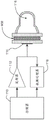
Fig. 1 is an exemplary schematic diagram of an apparatus for measuring mechanical properties of a sample.
Fig. 2 is an exemplary schematic diagram of a signal processing and data acquisition process using the implementation of fig. 1.
Figure 3 shows a representative experimental time-displacement curve obtained from clotting human blood.
Fig. 4 shows representative time-modulus curves and time-viscosity curves estimated using computer models.
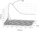
Fig. 5 shows an exemplary contour plot of the correlation between experimental time-displacement data and a computer model for a range of moduli and viscosities.
FIG. 6 shows a representative time-modulus curve estimated using a computer model in which viscosity remains constant.
Fig. 7 shows an example of using correlation masking to remove outlying modulus estimates.
FIG. 8 illustrates an exemplary embodiment of the present disclosure in which a focusing element is associated with a transducer assembly.
Fig. 9 shows an exemplary embodiment of the present disclosure in which an acoustic couplant is interposed between the transducer assembly and the test chamber.
Fig. 10 shows an exemplary embodiment of the present disclosure in which a focusing element is associated with the transducer assembly and an acoustic couplant is interposed between the transducer assembly and the test chamber.
Figure 11 shows an exemplary embodiment of the present disclosure in which the focusing element is associated with the test chamber and an acoustic couplant is interposed between the transducer assembly and the test chamber.
Fig. 12 shows an exemplary embodiment of the present disclosure incorporating a number of additional elements.
FIG. 13 illustrates an exemplary embodiment of the present disclosure in which a transducer assembly includes two separate transducer elements.
Figure 14 shows an embodiment of the present disclosure in which the transducer assembly includes two separate transducer elements, one dedicated to waveform transmission and the other dedicated to waveform reception.
Fig. 15 shows a computational grid for the finite difference time domain method described in this disclosure.
Fig. 16 shows a representative time-modulus curve estimated using an analytical model.
Detailed Description
Assessment of the hemostatic function in a timely and accurate manner can be achieved by measuring the mechanical properties of the blood sample at the time of coagulation. For example, the shear modulus of a blood sample over time can be measured during coagulation. In this application, "shear modulus" is interchangeably referred to as "modulus". The terms "rigid" and "stiffness" also refer to modulus.
In embodiments described in the present disclosure, a force-applying ultrasonication is applied to the sample within the test chamber. The forcing waveform applies acoustic radiation force to the sample, thereby causing motion. This movement is affected by the presence of the test chamber wall. Ultrasonic sensing pulses are applied to the sample and the difference in their echoes provides information about the movement of the sample. These differences may include phase changes or time offsets, either of which may be related to displacement. Finally, characteristics of these differences, such as the period of oscillation of the sample motion, are compared to an analytical or computational model to estimate the mechanical properties of the sample.
Embodiments described in this disclosure may include the elements shown in fig. 1. The transmitter 112 transmits an electrical waveform comprising at least one forcing waveform. These electrical waveforms are converted to ultrasonic waveforms by the transducer assembly 114. The forcing waveform induces sample motion within the testing chamber 116. The returned ultrasonic echoes are converted into electrical waveforms by the transducer assembly 114. These electrical waveforms are analyzed by the data processor 118 to estimate the mechanical properties of the sample. The details of this and other embodiments of specific implementations can be understood from the detailed description below. The timing of the transmission, reception, and data processing is controlled by the controller 110.
The present disclosure uses the phenomenon of ultrasonic radiation force, which may sometimes be referred to as acoustic radiation force. The ultrasonic radiation force is a physical force acting in the same direction as the propagation direction of the ultrasonic wave. It is the result of momentum transfer that occurs as the traveling ultrasonic waves are absorbed or reflected. The ultrasonic radiation force is confined to the ultrasonic beam; the magnitude of the force is proportional to the intensity of the ultrasound beam. Thus, a focused ultrasound beam may be used to apply a local acoustic radiation force field. In the present disclosure, the applied radiation force field is typically smaller than the test chamber to which it is applied. The sample motion induced by the radiation force field is initially localized to the force field area. However, over time, the displacement field will propagate outward from the force application zone.
In embodiments described in the present disclosure, ultrasonic radiation force is used to generate shear waves within a blood sample. Shear waves are mechanical waves in which the direction of particle displacement is perpendicular to the direction of wave motion. The shear waves of the present disclosure may be generated by directing ultrasonic waves of sufficient magnitude into a sample via a "forcing waveform". The force waveform carries sufficient energy that its absorption and reflection within the test sample generates an acoustic radiation force. The acoustic radiation force is induced along the direction of ultrasound wave propagation and can be considered as a physical force acting on a certain volume of the medium limited by the size of the ultrasound beam.
The induced shear waves will travel within the test chamber, reflecting from one or more walls. In some embodiments, a single reflected shear wave may be detected, and its time of arrival at the ultrasound sensing beam may form the basis for estimating the modulus of the sample. For some combinations of chamber geometry and sample mechanical properties, reflected shear waves may not be detectable. For example, the viscosity of the sample may be so high that, although a shear wave is generated, it does not have readily distinguishable characteristics and therefore cannot readily measure shear wave reflections from the wall. Nevertheless, the sample motion caused by the acoustic radiation force will exhibit perturbations caused by the induced shear wave interaction with the chamber walls. This characterization of the sample motion may form the basis for estimating the mechanical properties of the sample even if the shear wave itself is not clearly resolved in inducing the sample motion. In other cases, the shear waves may be repeatedly reflected within the chamber, generating resonances that may form the basis for estimating the modulus of the sample.
In this specification, the terms "test chamber", "resonance chamber" and "chamber" may be used interchangeably without loss of generality.
In this disclosure, the terms "forcing waveform" and "forcing pulse" will be used interchangeably without loss of generality. Also, the terms "sense pulse" and "sense waveform" will be used interchangeably without loss of generality.
The motion of the induced shear waves, including the perturbations of the shear waves associated with reflections and/or reverberation, may be estimated by taking into account the difference of echoes from the sensed waveforms. The difference does not mean a subtraction; rather, the term is used in a broad sense to refer to any aspect that differs between waveforms. The term "sensing waveform" is used herein to indicate an ultrasonic waveform whose magnitude is too small to generate significant acoustic radiation force, and thus too small to induce significant shear waves, but large enough to return an ultrasonic echo for difference analysis. In an alternative embodiment, the same waveform or waveforms may be used for both forcing and sensing.
The shear modulus may be related to other mechanical property metrics such as young's modulus and lame constant. Thus, while the present disclosure focuses on the measurement of shear modulus, these estimates may be translated to provide estimates of other mechanical properties.
In one embodiment, an apparatus is provided for launching a forcing waveform and a plurality of sensing waveforms into a sample within a resonant chamber and processing echoes returned from the sensing waveforms. The apparatus resolves mechanical features of the sample from the resonance features. For example, this device may include at least a controller, a transmitter, a transducer assembly, a resonant chamber, and a data processor.
Fig. 1 depicts a high-level block diagram of an exemplary embodiment of the present disclosure. In this embodiment, a controller 110 is provided to manage the timing of various aspects of the detection procedure. For example, the controller 110 may control the timing of transmit data digitization and data processing. The controller 110 may be a general purpose computer. In other embodiments, the controller 110 may be a dedicated controller, such as, for example, a Field Programmable Gate Array (FPGA). In one embodiment, a Xilinx Spartan 6FPGA may be utilized. Alternatively, an embedded processor or DSP chip may be used as the controller.
The controller 110 may control the timing of the transmitter 112, among other things. The transmitter 112 may be used to transmit a voltage waveform. The controller 110 may direct the transmitter 112 to connect and disconnect the power source at specific time intervals relative to the transducer assembly. In an exemplary embodiment, the transmitter 112 may transmit a desired waveform comprising a positive voltage, a negative voltage, and/or a neutral voltage at specific time intervals to achieve transmission between voltage levels. In other embodiments, the transmitter may be capable of multiple voltage amplitude levels, thereby being capable of generating a wider range of waveform shapes. In one embodiment, transmitter 112 includes a Supertex MD1810 level shifter to control the Supertex TC6320 MOSFETs to switch the +/-100V power supply and to control the Supertex TC2320 to clamp the transmit waveform to ground. Various hardware devices, firmware, and/or software, or combinations thereof, may also be used. The input signal to the transmitter 112 may come from the controller 110.
In the embodiment of fig. 1, the transmitter 112 transmits a voltage waveform to the transducer assembly 114. In this embodiment, the transducer assembly 114 is an ultrasonic transducer. The transducer assembly 114 may convert the transmit voltage waveform into an ultrasonic waveform and convert the ultrasonic echo into a receive voltage waveform. In one exemplary embodiment, the ultrasonic transducer is a single element composite piston transducer. However, other types of ultrasound transducers may be used, and these may include hardware, firmware, and/or software, or a combination thereof. In alternative implementations, the transducer may comprise a piezoelectric material (including single crystal materials), CMUT (capacitive micromachined ultrasonic transducer), relaxor ferroelectric transducer, thermal acoustic source or voice coil, other transducer technologies. In another alternative embodiment, the ultrasound emission is performed using a thermoacoustic method, wherein rapid heating results in thermal expansion, which in turn generates ultrasound waves. The transducer assembly 114 may also include an active transducer element (e.g., piezoelectric material) mounted to a single acoustic matching layer, which in turn may be mounted to a polymer mount. In one embodiment, the transducer employs backing air to improve electromechanical efficiency. In an exemplary embodiment, the transducer elements of the transducer assembly 114 have a wide bandwidth and have a sensitivity of between about 5MHz and 12 MHz. In some implementations, a series matching inductor is disposed between the transducer assembly 114 and the transmitter 112 to cancel the imaginary component of the transducer's electrical impedance. Other circuits may prove advantageous for matching the electrical impedance of the transmitter, transducer and receiver.
In an exemplary embodiment, a test sample is placed within the chamber 116 for testing. The transducer assembly 114 directs ultrasonic energy through a test sample held within a chamber 116. In some embodiments, the chamber 116 is axisymmetric and has a long axis that is collinear with the propagation vector of the ultrasound beam. In an alternative embodiment, only a portion of the chamber 116 is axisymmetric, while other portions have arbitrary geometry as needed to support filling the sample and avoid blocking the ultrasound beam.
In some embodiments, the chamber 116 is made of a material that is substantially more rigid (higher shear modulus) than the material being characterized. Thus, for the purpose of analyzing blood clots, a resonant chamber made of polystyrene or a similar rigid material can effectively be considered to have infinite rigidity. For example, the chamber 116 may be several thousand times, hundreds of thousands of times, or even more than a million times harder than the sample within the chamber 116. For example, blood clots typically have a shear modulus of several thousand pascals. Thermoplastics such as polystyrene have a shear modulus of about one gigapascal.
In some embodiments, the "forcing waveform" and the "sensing waveform" may be directed into the test sample in the chamber 116. The force application waveform may be an ultrasonic waveform capable of inducing shear waves in the sample via acoustic radiation force, while the sensing waveform may be a lower energy waveform for sensing aspects of the sample at a given point in time. These waveforms and their use are described in more detail below. The modulus of the sample can be estimated by analyzing the resonance of the ultrasound induced shear waves within the chamber 116.
In some embodiments, the data processor 118 incorporates a number of functions to enable analysis of the received echoes. For example, the data processor 118 may incorporate a receiver and a digitizer that together provide a digital signal to a general purpose processor for data analysis. In this embodiment, the receiver of the data processor 118 receives and amplifies electrical signals corresponding to the ultrasound echoes within the chamber 116. In this embodiment, the receiver would be operatively coupled to the transducer. The receiver may also include a protection circuit that prevents the high voltage waveform from flooding one or more amplifiers of the receiver. An example of such a protection circuit is Supertex MD0100. In some embodiments, the input of the protection circuit is connected to the transducer, and the output of the protection circuit is coupled to a low noise amplifier and then to a variable gain amplifier. Filtering stages may also be interposed to eliminate out-of-band noise. For example, in one embodiment, the input signal is amplified using an analog device AD8334 LNA/VGA combination.
In one embodiment, the receiver may be operatively coupled to a digitizer. In particular, the output of the amplifier may form the input of the digitizer. The digitizer converts the analog signal into a digital signal. In an exemplary embodiment, a 12-bit analog-to-digital converter (ADC), such as analog device AD9238, is utilized.
In the exemplary embodiment of fig. 1, the received echo data may be stored in a memory within the data processor 118. Such a memory may capture the digital output from the digitizer. The data processor 118 may comprise an FPGA, a general purpose processor, a dedicated DSP processor, or some combination of these. For example, the data processor 118 may include an FPGA memory cell, where echo data is temporarily buffered and then transferred to the embedded processor. In this case, the data is buffered again in the embedded processor and then transferred to the embedded PC for processing and modulus estimation. In an exemplary embodiment, the data processor 118 estimates the modulus through two distinct and interrelated steps. First, the data processor 118 analyzes the input echo signals to determine the displacement between echoes returned from the various sensing waveforms. In a second step, the data processor 118 compares the characteristics of the measured displacement to predicted characteristics predicted for analysis or computer modeling of a given chamber 116 geometry to estimate the modulus of the sample within the chamber 116.
Fig. 2 shows an example of an estimation process, comprising a data acquisition step 202, a motion estimation step 204 and a modulus estimation step 206. FIG. 2 also shows a plot 224 of modulus versus time, including data points 222, the estimates of which are shown in more detail in panels 202,204, and 206. The data acquisition panel 202 illustrates the data acquisition process. A series of ultrasonic emissions is emitted into the test chamber. The series of ultrasonic waveforms is: (1) sense pulse 210; (2) a forcing pulse 211; (3) sense pulse 212; (4) sense pulse 213; (5) sense pulse 214; and (6) sense pulse 215. These waveforms are merely examples, and the present disclosure is not limited to the particular number or order of waveforms shown.
In some exemplary embodiments, the sensing pulse is designed to exert a minimum acoustic radiation force on the sample while returning echoes with high signal-to-noise ratio and bandwidth. The sensing pulse 210 can be used to establish a baseline echo of the sample prior to application of the forcing waveform. On the other hand, the forcing pulse 211 is designed to exert a large acoustic radiation force field. After the forcing pulse 211, a series of low intensity sensing pulses (212-215) are emitted into the sample. The timing between the various sense pulses is controlled to maintain the accuracy of the downstream signal processing steps.
In an alternative embodiment, all of these waveforms have sufficient energy to apply acoustic radiation force. In this particular embodiment, these forcing waveforms also effectively act as sensing waveforms. Received echoes from any or all of these waveforms may be processed to estimate modulus using the methods and apparatus of the present disclosure. It is further contemplated that the present disclosure includes any combination of forcing waveforms, sensing waveforms, and the combined use of forcing waveforms/sensing waveforms.
Undisturbed clotting of healthy blood samples leads to the formation of hard clots. However, if the same sample is subjected to mechanical stress during coagulation, the shaped fibrin network may be damaged, resulting in the production of soft clots. Thus, any measurement of a mechanical property that applies a significant mechanical effect during coagulation has the potential to disrupt the evolution of the mechanical property being measured. This deviating effect of viscoelastic clot measurement can especially disrupt the measurement of soft clots formed in the blood of patients with dysfunctional hemostasis. This problem has been previously solved by the adaptive force measurement method disclosed in patent application PCT/US 2010/049342. The present application discloses a coagulation measurement system wherein the magnitude of the applied force is adjusted to limit the magnitude of the induced displacement. When the clot is soft, the applied force is reduced to avoid damaging the clot. When the clot is hard, the applied force is increased to maximize the sensitivity of the mechanical property estimation. The adaptive force method is equally applicable to the present disclosure, and is contemplated for use in conjunction with the present disclosure.
In one exemplary embodiment, the sensing waveform is emitted at intervals of about 122 microseconds, providing a sampling frequency of about 8.2 kHz. Other interrogation frequencies may also be used. In general, interrogation of harder materials requires higher interrogation frequencies because the shear wave resonance has a high frequency (assuming a constant resonant chamber geometry). By using a lower interrogation frequency, more accurate results can be obtained in softer materials to minimize cumulative radiation forces from the sensing waveforms and enable data to be collected over a longer period of time for a fixed data memory size. For example, for a blood sample, a suitable interrogation frequency is in the range of about 2kHz to about 16 kHz.
The combination of a single forcing waveform and multiple sensing waveforms may be referred to as an "ensemble". In one embodiment, the ensemble includes about 500 sensing waveforms. However, in other embodiments, the ensemble may include between about 16 and about 2048 sensed waveforms. Other ensemble sizes may be used to measure materials with higher or lower stiffness. An ensemble is processed to produce a single modulus estimate.
In some embodiments, the acquisition time for a single ensemble is about 62 milliseconds. However, the acquisition time may be shorter or longer. For example, accurate results may be obtained by using an acquisition time of about 20 to 30 milliseconds for a single ensemble. For example, even shorter acquisition times, such as 10 milliseconds, may also be used. A longer ensemble period enables accurate measurement of a wider range of moduli. In some embodiments, the ensemble may be repeated at a rate of about 16Hz to measure the rapidly changing modulus. In other embodiments, the physical process under examination (coagulation) is slow enough that the ensemble can be repeated at a rate of only once in six seconds and still provide data that accurately reflects the change in modulus.
In some embodiments, it may be advantageous to limit the range of mechanical properties considered in a given ensemble based on previously measured mechanical properties for the same test chamber. For example, during coagulation, it is expected that the shear modulus will vary very smoothly over time, provided that the measurements are taken at sufficiently small time intervals. For example, if the modulus in a given measurement is 1.0kPa, it may be advantageous to limit the range of possible moduli in successive measurements to a range between 0.5kPa and 2.0 kPa. Even where the modulus range is not explicitly limited, it may be advantageous to smooth the modulus estimates over time by linear filtering (convolution with a filter kernel) or non-linear filtering methods (such as median filtering) or a combination of both.
Each of the transmit waveforms travels from left to right along the hourglass beam shape as shown by the series of vertical lines within the test chamber of the faceplate 202 of fig. 2. When interrogated by the sensing waveform 210, the sample is at rest. Due to the inertia of the sample material, the sample remains in a stationary state when impacted by the forcing waveform 211. However, immediately after the forcing waveform passes, the acoustic radiation force applied by the forcing waveform 211 causes the sample material along the beam to move in the direction of propagation of the forcing waveform 211. In the embodiment of fig. 2, this motion is first visible when the sample is interrogated by the sensing waveform 212. This motion is shown in the figure as a shaded region below the ultrasound beam.
When the sensing waveform 213 is emitted, the radiation force induced displacement begins to propagate outward from the acoustic beam toward the test chamber wall. The displacement propagates primarily in the form of shear waves. Over time, the shear wave reflects off the wall, passes back through the acoustic beam, and then reflects off the wall again. This repeated reflection is indicative of the resonance of the shear wave within the test chamber. The reverberation eventually settles out as viscous and other losses within the sample attenuate the propagating shear wave. Note that for some combinations of modulus, viscosity, and resonant chamber velocity, the induced shear wave may reach the chamber wall so quickly that the observer does not see it propagating. Instead, it appears that the entire content chamber is oscillating rhythmically. While different in nature from propagating shear waves, such standing wave modes are one example of resonance and are contemplated by the present disclosure. In other combinations of modulus, viscosity, and chamber geometry, the excited shear wave may be quite discrete in time and space, and the shear wave reflected from the wall is a waveform that is discrete in space and time. Measuring modulus by examining the arrival times of such different pulses is one possible embodiment of the present disclosure. In this embodiment, the shear wave echo reflection arrival time is one aspect of the difference in the received waveforms compared to the same aspect of the modeled difference (shear wave reflection arrival time).
In other implementations, the chamber 116 is so small relative to the shear wavelength that a true shear wave is not generated. In this case, it can be said that there is no resonance for this combination of modulus and chamber geometry. In reality, however, the induced displacement is still affected by the presence of the chamber walls. This boundary effect is used to alter the induced displacement compared to what would be expected if the same force were applied to an infinite or semi-infinite medium. Such variations may take the form of variations in time-dependent displacement relative to the displacement predicted for semi-infinite media. This variation is an aspect of the estimated time-displacement caused at least in part by the boundary effect of the chamber wall. In this case, the time course of the induced displacement can be taken into account in conjunction with the chamber geometry to estimate the sample modulus. In one embodiment, the modulus estimation is performed by comparing the measured displacement to a series of computer model predicted displacements, as described in more detail below.
The presence or absence of resonance can be determined by analyzing the difference of the received echoes as a whole or by estimating the time-shift by analysis in particular. In one embodiment, the time-displacement curve is analyzed to determine if a trough is present (negative peak displacement). If such a trough is found, it can be inferred that resonance is occurring. If no dip (negative peak) is observed in the time shift, it can be concluded that no resonance is present. This conclusion about the presence or absence of resonance can be expressed as a parameter indicative of the strength of the resonance. In this simple example, the parameter holds a value of 1 when a time-displacement trough is detected, and holds a value of 0 when such a trough is not detected. This concept can be further extended by considering whether a displacement peak is detected in combination with a displacement trough, as this would indicate a stronger resonance. An alternative parameter indicative of the resonance strength is the average of the time-displacement curve. When no resonance is present, the time-displacement curve will be predominantly unipolar and will therefore have a high average value. Alternatively, when the resonance is strong, the time-displacement curve will exhibit strong oscillations around zero and will therefore have a low average value. An alternative parameter indicative of the strength of the resonance is to measure the ratio of the average displacement over the ensemble to the peak displacement. High values of this parameter indicate weak resonances. Other parameters may be calculated to indicate the strength of the resonance.
Each of the sensing waveforms returns an echo from an impurity (acoustic scatterer) within the sample. In the case of whole blood, these impurities are primarily red blood cells. The present disclosure can also be used to measure homogeneous materials, such as plasma, by adding polystyrene microspheres or other agents that act as acoustic scatterers.
As the acoustic diffuser moves away from the ultrasound transducer, the acoustic path length between the sensor and the diffuser may lengthen. Assuming a constant speed of sound, this will result in the echoes arriving at a later time as the target is pushed further by the resonant shear wave. Also, in case the scatterer has moved closer to the ultrasound transducer, the echo will arrive earlier. These changes in echo arrival time are differences between these waveforms that indicate potential movement of the sample. If the ultrasound propagation velocity (speed of sound c) is known in the sample or can be measured, the measurement time delay can be related to the potential physical displacement according to the well-known relation dx = c dt/2.
In the previous expression, dt is the measured time offset between echoes, c is the speed of sound (ultrasound, not shear waves), and dx is the estimated relative displacement. Note, however, that the present disclosure does not require knowledge of the speed of sound, as the displacement characteristics used to estimate the modulus do not necessarily include absolute displacement. In one embodiment of the present disclosure, the phase shift between the echoes of the various sensing waveforms is measured. These phase shifts are differences in the received waveform due to potential movement of the sample. For a resonant sample, these phase shifts will exhibit oscillatory characteristics with a frequency related to the modulus of the sample. The observed characteristic (oscillation frequency) can be compared to the predicted characteristic (oscillation frequency predicted by theory) to estimate the modulus of the sample.
It is well known that the speed of sound in blood changes when blood coagulates. However, this evolving speed of sound has little or no effect on current measurements for at least two reasons. First, as described above, many algorithms for correlating measured displacement with modulus do not require knowledge of the true displacement; only the relative displacement needs to be known. Second, the change in sound speed occurs within a few minutes, whereas the measurement ensemble described herein occurs within a few milliseconds. Thus, the slowly evolving speed of sound has no appreciable effect on the time delay estimate for any single ensemble.
Echo data from the ensemble is processed to find differences in the received waveforms indicative of target motion along the ultrasound beam. One process of analyzing these waveform differences is referred to as "motion estimation," and is conceptually illustrated in motion estimation panel 204 of FIG. 2. Each echo resulting from, for example, sense pulses 212 to 215 is compared to a reference echo resulting from sense pulse 210 to find the time delay between them. The time delays between the various echoes can be converted into displacements by using measured or assumed sound velocities. All displacement estimates for a single ensemble are combined to form a time-displacement curve 220, as shown vertically to the right of the motion estimation panel 204. The time-displacement curve is a characteristic indicative of the modulus of the sample. It is noted that the exemplary time-displacement curves show the oscillations associated with shear wave resonance, and the attenuation of those oscillations associated with the chamber geometry and the inherent viscous damping of the medium.
The motion estimation algorithm used to calculate the difference of the received waveforms may be an algorithm known in the art. Exemplary algorithms include those described by Kasai (c.kasai, k.namekawa, a.koyano and r.omoto, "Real-Time Two-Dimensional Blood Imaging Using an Autocorrelation Technique") IEEE trans. Sonic ultras, volume SU-32, pages 458-464, 1985); loupas (Loupas et al, "Experimental evaluation of velocity and power for ultrasonic blood flow imaging, by means of a two-dimensional autocorrelation approach" ("velocity and power estimation for ultrasonic blood flow imaging experimentally assessed using a two-dimensional autocorrelation method"), IEEE Trans ultrasound ferro flow Contr.42:689-699, 1995); and those proposed by Walker (us patent 8,306,293).
Alternatively, the waveform difference values may be analyzed to estimate motion by finding the time delays corresponding to the peaks of the correlation function between the various received echo signals. The direct measurement of the time delay can be extended to the measurement of the delay envelope of the demodulated waveform. As another alternative, the relative phase shift between the various received echo waveforms is a difference indicative of the motion of the sample. These phase shifts can be calculated digitally by comparing complex hilbert transforms of waveforms associated with different transmissions. As yet another alternative, the received waveform may be digitally sampled at intervals of about 1/4 of a cycle to approximate in-phase and quadrature (IQ) signals. This so-called direct sampling in-phase and quadrature (DSIQ) sampling scheme has been used previously to simplify the ultrasound beamformer design (US 20070016022 A1) and can be applied to compute waveform differences representative of motion in this disclosure. In another embodiment, the received ultrasonic waveform is processed via quadrature demodulation to produce a complex waveform, where the angle between the real and imaginary parts indicates the phase of the received signal. The phase is a difference indicative of the motion of the sample.
Fig. 3 shows an experimental time-displacement curve obtained by the present disclosure. Waveform differences are analyzed to generate displacement estimates based on a series of 300 ensembles. Each ensemble consists of a single forcing waveform and 512 sensing waveforms transmitted at a pulse repetition frequency of 8,206hz. Larger displacements and lower frequency oscillations were found earlier in the clotting process. The first time-displacement curve 302 does not show oscillations, which become clearer as the clot forms a higher modulus. A simple algorithm based on only the mechanical resonance frequency would invalidate the data for curve 302. The curve corresponds to the modulus at which the chamber geometry cannot support resonance. However, the present disclosure may estimate modulus even if no significant oscillation is visible, such as is the case for the time-displacement curve 302. In this case, the modulus may be estimated by comparing the measured displacement (characteristic) to a computer model or analytical model (predicted characteristic) of the dynamic sample motion induced by the forcing waveform.
The modulus estimation panel 206 of fig. 2 shows an exemplary process of estimating the shear modulus of a sample from an experimentally determined time-displacement curve 220. The shape of the time-displacement curve 220 is a characteristic of the estimated displacement, which in turn may be described as a waveform difference. In one exemplary embodiment, a computer model has been used to generate a set of reference models, where each reference model is a predicted time-displacement curve for a given shear modulus and viscosity for a particular test chamber geometry. These reference models incorporate predicted features associated with the moduli of the computer model. Such a computer model may utilize a finite difference time domain method, as described below. Alternatively, finite element or boundary element computational models may be used. The processor searches the library of reference models (predicted features) for the one that most closely matches the experimentally measured time-displacement curve 220 (features). In this embodiment, the library of reference models may be formed offline using Finite Difference Time Domain (FDTD) models, as described below. Alternatively, the reference model may be calculated using a finite element or boundary element model. The reference models (predicted features) are shown as gray curves in the modulus estimation panel 206, each corresponding to a different shear modulus. Each reference model of the modulus estimation panel 206 shows time-displacement curves 220 (features) that overlap in black. In this particular exemplary embodiment, the reference model for 3kPa shear modulus most closely matches the time-displacement curve 220. The modulus and viscosity used to form the reference model are estimates of the modulus and viscosity of the sample. In other embodiments, the computer model calculates a series of models of latent modulus and viscosity corresponding to a given time-displacement curve immediately after the time-displacement curve is generated. However, the computational load of such a dynamic modeling approach may be too heavy relative to searching for a predefined reference model. An improvement in computer power or a reduction in algorithm complexity will enable dynamic calculation of the reference model. Such a method would allow a more accurate estimation of modulus and/or viscosity. This approach can also be combined with a coarsely sampled (in modulus dimension) library of reference models to trade off computational complexity against storage requirements.
Note that the term "analytical model" may refer to something as simple as an expression relating resonance frequency to modulus, or something as complex as a full time-displacement waveform predicted by analyzing the expression. In the case of using a full time-displacement waveform as a model, it may be advantageous to evaluate the analytical expression and construct a set of reference models, similar to the method described above for calculating the model.
In an alternative embodiment, no explicit reference curve is used to estimate the modulus. Instead, a characteristic of the time-displacement curve, such as the oscillation period thereof, is calculated, and this characteristic is used together with the oscillation period predicted by the analysis model (predicted characteristic) to estimate the modulus. An exemplary analytical model is derived below. The model shows that the resonance frequency (inverse of the period) is related to the resonance chamber radius and the material modulus and density by the following expression:

the expression can be rearranged so that the modulus can be directly estimated from the measurement period:

where T is the resonance period. Therefore, the oscillation period is a feature that can be compared with a predicted feature (oscillation period of the analysis model) to estimate the modulus. Also, the period of oscillation is an aspect of the induced motion caused at least in part by resonance within the chamber. Note that in the case of analytical models, it is not necessary to test a series of model predictions, but the step of comparing between predicted and experimental features may be performed by simple mathematical expressions. The present disclosure contemplates such a method. Alternatively, the resonance frequency may be used with the above expression to estimate the modulus.
In some applications, it may not be necessary to estimate the mechanical properties. Instead, it may prove useful to characterize the mechanical properties. In this context, we intend that the concept "estimating mechanical properties" refers to the quantitative estimation of well-known mechanical properties such as shear modulus. Alternatively, we consider the concept "characterizing a mechanical property" to mean determining something about the mechanical property, but not necessarily setting units for it, or even determining it in a directly proportional manner. For example, estimating the resonant frequency of a sample characterizes the mechanical properties of the sample without taking the additional step of referring to the true modulus. It may be useful to generate a plot of "resonant frequency" versus time rather than a plot of modulus versus time. Although the "resonance frequency" is not the same as, or even proportional to, the modulus, tracking the resonance frequency will allow important information about coagulation to be obtained. We therefore recognize the utility of this characterization without having to relate it to fundamental mechanical properties such as shear modulus.
The resonance period is a feature that can be used as a basis for estimating or characterizing mechanical properties. Considering that the period is only the inverse of the frequency, the estimate of the period is equal to the estimate of the frequency and vice versa. The resonance period may be estimated from the difference between the received waveforms in various ways. For the purposes of this discussion, consideration regarding differences between received waveforms is limited to motion estimates derived from the received waveforms, although other methods are contemplated, particularly methods that include phase changes estimated from the received waveforms. We first consider a time-displacement curve, as shown in fig. 3. The period of oscillation of such a curve can be estimated by taking a Fast Fourier Transform (FFT) and estimating the frequency at which the energy is at its peak. Alternatively, the mean value may be subtracted from the time-displacement curve and then autoregressive power spectral density estimation using the Burg method. The frequency of the peak energy corresponds to the oscillation frequency. The ROOT-MUSIC algorithm may also be used to estimate the oscillation frequency. Other spectrum estimation techniques may be similarly employed.
The oscillation frequency may also be estimated in other ways. Specific algorithms for estimating the frequency of the decaying sinusoid are known. Ruiz et al in D.P.IEEE Transactions on Signal ProcessingOne such algorithm is described in the paper "Parameter estimation of amplified sinusoidal using a high order correlation method" in volume 43, 11, month 11 of 1995. Published in T.P.Zieli ń ski and K.DudaMetrology and Measurement SystemsAn algorithmic review specific to this problem is presented in the paper "Frequency and damping estimation methods-an overview" (review of Frequency and damping estimation methods) at volume 18, no. 4, 2011. Other methods are also provided.
The period of oscillation can be estimated directly from the time-displacement signal. In one approach, the time of the first trough in the displacement (the most negative displacement) is used as an estimate of 1/2 of the period of oscillation. Since the time-shift signal is sampled discretely in time, while the period may take on continuous values, it is advantageous to apply interpolation. In one embodiment, the time-displacement signal is directly interpolated to a higher sampling frequency prior to the time that the trough is located. This interpolation may be performed via FFT, piecewise cubic spline interpolation, or other known methods for resampling. Alternatively, discrete samples where a trough appears can be identified and the true location of the trough found via an analytical interpolation scheme. In one embodiment, a parabola is fitted to the discrete valley and its nearest two neighbors, and the time of the minimum of the parabola is used as the estimated time of the trough. Alternatively, such interpolation may be performed using a higher order function including a piecewise cubic spline.
The period of the displacement oscillation may also be estimated by other methods. In an alternative method, the position of the first trough and the second peak are determined and the time interval between them is an estimate of 1/2 of the oscillation frequency. Note that it is generally preferable to use the second peak because the timing of the first peak is distorted by the application of the forcing pulse. This peak finding strategy can be further extended by estimating the position of multiple positive and negative peaks and combining these positions to estimate the period. In one embodiment, first and second troughs, and second and third peaks are identified. Consider the first trough at time t n1 The time of the second peak is t p2 The second trough having a time t n2 And the third peak has a time t p3 . In this case, a period may be associated with each of these peaks and valleys, as follows:
t n1 =T/2+e 1
t p2 =T+e 2
t n2 =3T/2+e 3
t p3 =2T+e 4
wherein e 1 、e 2 、e 3 And e 4 Representing an error term resulting from noise in the peak/trough position estimate. The oscillation period can be directly measured from the estimated times of these peaks and valleys by the following expression:

this expression has the advantage that the weighting of later peaks and troughs, which will have lower relative amplitudes and will therefore be more susceptible to noise, is reduced. Alternatively, the period may be estimated from the same peak and valley times by the following expression:

the present disclosure contemplates other variations of the method, including more or fewer peaks and troughs, and alternative expressions for estimating the period from the time of the peaks and troughs.
The oscillation period may alternatively be estimated from the position of the zero crossings of the time-displacement curve. Although the peak-to-trough time interval is 1/2 cycle, the zero crossing interval is about half that, 1/4 cycle. The method of estimating the period of oscillation by combining the peak and trough times described above can be easily modified to incorporate the zero crossing times to estimate the period of oscillation. Many algorithms for estimating the zero crossing time are known. One method fits a straight line to data points near the zero crossing and finds the time at which the fitted straight line equals zero. Higher order methods using polynomials or splines are also contemplated.
In some embodiments, the shear modulus estimate for each ensemble is plotted as a single point on the curve, as shown in fig. 2. In this particular embodiment, the exemplary calculations represented by panels 202,204, and 206 produce data points 222. Repeated calculations over a period of time for multiple ensembles produce a shear modulus curve 224.
In an exemplary embodiment, the similarity between the reference model and the experimentally determined time-displacement curve 220 is quantified using a normalized correlation coefficient. The normalized correlation coefficient between two different signals a [ n ] and b [ n ] is given by the following equation:

wherein And is
Fig. 4 shows the results of the modulus estimation of the present disclosure as applied to clotting human blood. A small amount of kaolin was added to the human whole blood sample. The top graph shows the modulus estimated over time, with the reagent (kaolin) added to the blood sample at time zero. The middle graph shows the estimated viscosity over time. The bottom graph shows the normalized correlation between the experimental time-displacement curve and the time-displacement curve predicted by the finite-difference time-domain model described below. The model used in this figure takes into account the modulus between 10Pa and 10,000pa and the viscosity between 0.025Pa s and 0.8Pa s. A total of 16,032 combinations of modulus and viscosity were modeled. Assume that all models have a density of 1.06g/cm 3 The density of (c). The geometry of our experimental laboratory was modeled on a spatial grid sampled at 100um in each dimension. The resonant portion of the test chamber consisted of a cylindrical region of 4.2mm diameter and about 1.5mm in length, with a hemispherical cap of the same radius as the cylinder. The first 18 time-modulus estimates were removed from the experimental data and the model, and then the correlation between the experimental data and the model was calculated. The best fit line was removed from the experimental time-displacement and computer model time-displacement predictions and the correlation was calculated. The wrong modulus estimation occurs at the early stages of clot formation because the model cannot allow liquid blood or blood to have a low modulus at the very early stages of clot formation.
The results shown in fig. 4 are notable, in part, because of the relatively high correlation between the experimentally determined time-displacement curves and the predictions of the FDTD model. As can be seen from the bottom graph in fig. 4, the correlation between the FDTD model and the experimentally measured time-displacement curve is well over 0.95 for well formed clots. This provides a strong indication that the computational model is one that is suitable for these experimental conditions. The correlation between the model and the experimental data is much worse for the liquid blood phase. This is not surprising, since in this case the softest model corresponds to a modulus of 10Pa, which is far from the liquid state, which has a modulus of zero. Similar correlation tests were performed by numerical evaluation of the resulting time-displacement waveforms by the analytical model derived below. Although not shown, these results are closely related to the experiment; the utility of the analytical model is verified. The analytical model is less correlated than the FDTD model. This is likely because the analytical model assumes an infinitely long cylinder, whereas FDTD assumes a cylinder like the capping cylinder of a real experimental test chamber.
The correlation between the experimental time-displacement curve and a series of reference models can be plotted as a two-dimensional function of modulus and viscosity, as shown in the contour plot of fig. 5. The figure shows the normalized correlation between the experimental time-displacement curve and the time-displacement curve predicted by the finite-difference time-domain model described below. The model used in this figure takes into account the modulus between 10Pa and 10,000pa and the viscosity between 0.025Pa s and 0.8Pa s. The best fit line was removed from the experimental time-displacement and computer model time-displacement predictions and then the correlation was calculated. The peak correlation lies within the smallest ellipse labeled 0.95 in the figure. The position of the peak corresponds to the estimated modulus and viscosity of the particular exemplary ensemble. The smallest ellipse (highest correlation) is oblong, distributed over a large range of viscosities and a smaller range of moduli. A small amount of noise may result in a continuous estimate to wander around the peak correlation, although this may always be limited to high correlation contours. The shape of the 0.95 correlation contour indicates that the estimate of viscosity can include significant variation as evidenced by the width of the contour in the viscosity dimension. Because the contour in this dimension is narrow, the change in modulus estimate will be relatively small. However, the correlation functions are inseparable in the viscosity and modulus dimensions. Conversely, an error in offsetting the viscosity necessarily offsets the modulus. This observation shows that it is possible to fix this parameter and obtain a more accurate and repeatable estimate of shear modulus, given that the viscosity can be assumed to remain at a certain value. This method of fixing the viscosity brings about the advantage that what is a two-dimensional search (modulus and viscosity) is limited to a one-dimensional search (modulus), thereby improving the calculation efficiency.
Fig. 6 shows the results of modulus estimation with viscosity held constant. The top graph shows the modulus estimate. The middle graph shows the viscosity, which is fixed to a value of 0.25Pa s. The bottom graph shows the correlation between the model and the experimental time-displacement. The model used for these estimations is in many ways the same as the model used to obtain the results of fig. 4. There are two notable differences. First, the modulus varies between 0.01Pa and 10,000Pa. Second, the viscosity remains constant at a value of 0.25 pas. A total of 1,167 models were created. The results of fig. 6 show a significant improvement in modulus estimation prior to formation of a firm clot. Although the correlation of these early estimates is rather low, they are significantly higher than in the case of fig. 4. This result is encouraging because it suggests that adjusting the model range to introduce a lower modulus may yield a closer estimate of mechanical properties when the modulus of the sample is lower. This is another confirmation of the effectiveness of the computational model. The results of fig. 6 require less than 1/10 of the calculation of the results of fig. 4, with no loss of quality of the results.
The computational and analytical models described in this disclosure have a number of adjustable parameters that can be estimated or alternatively kept constant, depending on the particular sample and chamber geometry. In the foregoing example, it has proven advantageous to keep the sample viscosity and density constant and evaluate the model for a range of shear moduli. In human blood, it is reasonable to keep the density at a constant value, since the differences between individuals are rather small. Although the viscosity may vary slightly, the advantage of limiting the freedom of estimation may outweigh any absolute error in viscosity. For different samples, it may be advantageous to allow for viscosity or density changes while keeping the modulus constant. In other embodiments, the chamber geometry may not be precisely known, and the models may allow certain aspects of the chamber geometry to vary from model to model.
In some embodiments, the values of the normalized correlation coefficients may be used to reject modulus and viscosity estimates that are not reliable and likely to be correct. For example, the normalized correlation coefficient may be used to reject modulus and viscosity estimates where bubbles in the acoustic path corrupt the potential ultrasound echo. Processing the corrupted echo data will produce a time-displacement curve that is also too noisy. While a typical correlation between the best reference model and the experimental time-displacement curve may be 0.98, the correlation of the compromised time-displacement data may be reduced to, for example, 0.40. This significant reduction in correlation will clearly indicate that the measurement is unreliable and should be rejected. This process of rejecting estimates with low correlation may be referred to as "masking". Suitable thresholds may be determined empirically based on experimental experimentation, but a reasonable threshold may be about 0.9.
Masking the shear modulus estimate from its peak correlation with the reference model would be particularly valuable for clearing noisy estimates that form before blood has begun to clot. For liquid blood, the time-displacement estimation shows very large displacements, which are usually irregular. The irregularity of these curves allows them to fit almost any reference model, although this fit is only a coincidence and not an actual match. Furthermore, the reference model may not actually be applicable until coagulation begins to form a solid "clot". For example, models based on viscoelastic solids are not suitable for liquid samples. In these cases, the quality of the match, and hence the correlation coefficient, may be quite low, despite the presence of the fit. By removing only modulus estimates for which the peak correlation is below a reasonable threshold, the erroneous modulus estimates associated with liquid blood can be removed directly.
The concept of "correlation masking" was applied to the experimental results of fig. 6, and the results are shown in fig. 7. The top graph shows the raw modulus estimate; including the two data points at which the measurement was started. These data points are clearly in error. The middle graph shows the correlation between experimental data and the best-fit model. A correlation threshold of 0.6 was chosen to remove the data points that are clearly erroneous. The bottom graph in fig. 7 shows the modulus estimate remaining after removing the modulus with correlation below 0.6. Two erroneous modulus estimates are eliminated.
The correlation between the model and the experimental time-displacement estimate may also be used for other purposes. In an alternative embodiment, a plurality of different models are formed in which both the mechanical properties and the underlying assumptions vary. For example, one model series may be developed in which the sample is assumed to be a viscoelastic solid, while a second model series assumes the sample to be a liquid sample. Within each series, the mechanical properties are allowed to vary. In this embodiment, the data processor tests the correlation between each model in the two series and the estimated time-displacement curve. The particular model with the best correlation to the time-displacement curve will indicate both the value of the mechanical property and the type of material that best describes the sample. In this particular example, the material type is a viscoelastic solid or liquid.
The library of reference models necessarily contains a limited number of reference models. In some embodiments, the modulus estimates may fall between the reference models. This limitation can be overcome with less computational cost by interpolating the correlation coefficient around the measured peak to locate the shear modulus corresponding to the best correlation, whether or not the reference model is calculated for that modulus. In the simplest case, where the viscosity remains constant and only the modulus is allowed to vary, the modulus estimate can be determined by locating the peak of the parabolic fit by best fitting the correlation of the reference model and the correlation of its two nearest neighbors. Other interpolation schemes, including spline-based and higher order polynomial based interpolation schemes, may produce more accurate results. Furthermore, the interpolation described herein may be applied to a two-dimensional (modulus-viscosity) estimation by using a two-dimensional interpolation scheme. The experimental results presented here all use interpolation to form the modulus estimate.
Experimentally determined time-displacement curves can be corrupted due to various physical and electronic effects. For a finite volume test chamber, the forcing waveform may generate a significant reverberant ultrasound echo that may extend into the acquisition period of the subsequent sensing waveform. In one exemplary embodiment, the effects of such reverberation may be mitigated by designing the frequencies of the forcing waveform and the sensing waveform to be within different frequency bands, and then using analog or digital filtering to suppress the reverberation associated with the forcing waveform. In an alternative embodiment, the sensing waveform sent shortly after the forcing waveform may be removed from the time-displacement estimation curve, and then the reference model searched for the best fit. The method of rejecting erroneous time-displacement estimates may be performed statically (e.g., assuming the first 6 estimates of each time-displacement curve are erroneous) or dynamically (e.g., computing a quality metric for the time-displacement estimates and discarding estimates whose quality metric is below a certain threshold).
FIG. 16 shows an experimentally determined time-modulus curve using analytical expressions to correlate the measured period of displacement oscillations with shear modulus. The method uses equation 58 to relate the resonant frequency to the modulus. The resonance period is estimated from the time difference between the first trough of the displacement to the second peak of the displacement. This approach yields a reliable estimate of the modulus of the clot, although it is challenged by an early fluid phase before clotting begins. As described elsewhere in this disclosure, these erroneous estimates may be masked according to a parameter indicative of resonance strength. This analytical estimation of modulus is quantitatively different from the estimation based on computational models. This may be due to the different geometry assumptions adopted by the two methods. The analytical model assumes an infinitely long cylinder, while the computational model assumes a cylinder similar to the capping of an experimental test chamber.
The present disclosure contemplates estimating mechanical properties based on at least three different, but interrelated, mechanical behavior patterns. In the first mode, a force pulse is applied to the chamber and it is possible to excite mechanical resonance of the sample confined by the test chamber. In one embodiment, the resonance frequency is the basis for estimating the shear modulus of the sample. It is noted, however, that for certain combinations of modulus, viscosity, density and chamber geometry, true resonance may not be induced. For example, if the sample viscosity is higher than the modulus, the system will be under-damped and no resonance will occur. However, as the clot hardens, the modulus will increase while the viscosity remains relatively constant. Thus, when the clot hardens, the exemplary devices disclosed herein will be able to detect the onset of resonance. This transition may provide a useful and simple indication of clot formation.
In another embodiment, the viscosity of the sample is sufficiently low relative to the modulus that a well-defined (in space and time) shear wave can be induced in the sample. Where the shear wave is confined in time and space, the reflection of the shear wave from the chamber wall will be clear and can be readily detected from the difference between the echoes received from scatterers within the sample. Knowing the chamber geometry (shear wave path length), the shear wave velocity (and hence modulus) can be estimated directly from the arrival time of the shear wave echo from the chamber wall. As with the previous resonance example, there may be certain combinations of mechanical properties and geometry for which clearly measurable shear waves cannot be generated. As with the resonance example, a transition between a state in which a clearly measurable shear wave cannot be generated and a state in which a clearly measurable shear wave may be generated may provide a good alternative to the transition from liquid blood to a formed clot. Thus, the timing of such transitions can provide a useful measure of clot formation time.
In the third embodiment, neither the clear resonance nor the propagating shear wave is easily measured. However, this does not exclude an estimation of the mechanical properties within the test chamber. For any sample within a confined chamber, the chamber walls will change the apparent mechanical impedance of the sample. In this context, mechanical impedance describes the relationship between the applied force and the resulting displacement. A very soft sample in a very large test chamber will exhibit a mechanical impedance very similar to a sample in an infinite test chamber. Alternatively, a hard sample in a small test chamber will exhibit a mechanical impedance that is very different from that observed in a larger test chamber. With dynamic force application, the magnitude of the sample viscosity will further affect the perceived mechanical impedance. The present disclosure contemplates comparing a model of a sample within a test chamber to experimental measurements to estimate mechanical properties of the sample. In this embodiment, the influence of the wall (boundary effect) is explicitly taken into account. Since the influence of the boundary (wall) of a given chamber geometry varies depending on the mechanical properties of the sample, a transition from insignificant to significant boundary effects may be used as a surrogate for the transition from a liquid blood sample to a formed clot.
In another embodiment shown in FIG. 8, the transducer assembly 114 of FIG. 1 incorporates a focusing element 802. The addition of the focusing element increases the intensity of the applied forcing waveform and increases the intensity of the received echoes. Furthermore, the use of the focusing element 802 enables the use of larger transducer elements within the transducer assembly 114. Applicants herein fully contemplate alternatives to such an apparatus.
In one exemplary embodiment shown in fig. 9, separable test chamber 116 is provided with a couplant 902. In many commercial applications, the separable test chamber is particularly useful as a consumable component. In this application we refer to the detachable test chamber as a "consumable", whilst recognizing that it may be a reusable component. In the context of this embodiment, an acoustic circuit is described that includes the transducer assembly 114 (instrument), the couplant 902 (consumable), and the test chamber 116 (consumable). In addition, a focusing element may be interposed between the transducer assembly and the couplant, or between the couplant and the test chamber. In an alternative embodiment (as shown in fig. 10), the focusing element 1004 is combined with an instrument, and the coupling agent 1002 is associated with the instrument or consumable. The acoustic path out from the transducer assembly is: the transducer assembly 114 (instrument), the focusing element 1004 (instrument), the coupling agent 1002 (instrument or consumable), and the test chamber 116 (consumable). In yet another alternative embodiment, the focusing element incorporates a consumable, as shown in FIG. 11. In this embodiment, the coupling agent 1102 can be associated with an instrument or consumable, while the focusing element 1104 is associated with the consumable.
In the exemplary embodiment of fig. 11, the ultrasonic waveform travels from the couplant 1102 to the focusing element 1104. The focusing element 1104 may be shaped so that it refracts into the ultrasonic energy and focuses it as desired within the resonant test chamber. In some embodiments, the focusing unit 1104 is a thermoplastic, but other suitable materials may be used instead of or in addition to thermoplastics. In one possible embodiment, the couplant 1102 may include a liquid such as water. In another possible embodiment, the coupling agent 1102 may comprise a water-based or oil-based gel such as those commonly used for ultrasound imaging.
The focusing element 1104 focuses the ultrasonic energy into the chamber 116. The chamber 116 may also be interchangeably described as a resonance chamber, or a test chamber. The focusing element 1104 is designed such that its curvature and speed of sound act to refract the transmitted ultrasound waves into a focused beam. The focusing elements 1104 may be designed to form sharply focused or widely focused beams. A sharp focus tends to apply a higher magnitude of radiation force, however, a sharp focus may make the overall system more sensitive to smaller errors in aligning the ultrasound beam and the resonant chamber 116. Alternatively, the focusing element 1104 may be designed to focus the ultrasound beam more broadly. This may generate a smaller magnitude of radiation force, but may make the system less sensitive to alignment errors of the ultrasound beam with the resonant chamber 116.
Fig. 12 shows an alternative embodiment comprising a durable instrument and a consumable test cartridge. The controller 110, emitter 112, transducer assembly 114, data processor 118, transducer alignment feature 1210, and clamping mechanism 1214 are incorporated into the instrument. The assay chamber 116, couplant 1202, focusing element 1204, chamber alignment feature 1212, thermal control unit 1220 and surface modification feature 1230 are incorporated into a consumable.
In the embodiment of fig. 12, the consumable component is placed in acoustic contact with the instrument by action of the clamping mechanism 1214. In one embodiment, the clamping mechanism is a lead screw actuated by a stepper motor. Other embodiments may include, for example, a mechanical actuating lever or some other mechanical mechanism. Where the couplant 1202 is a fairly strong material, the clamping mechanism 1214 may require a large amount of force to eliminate any air gaps and make good acoustic contact. In one embodiment, clamping mechanism 1214 applies a force of approximately 110 newtons for clamping a single resonant chamber 116. In an alternative embodiment, where a single consumable consists of multiple resonant chambers, a single clamping mechanism may be shared across the channels. In this case, the clamping mechanism may be required to apply a force in excess of 110 newtons. For example, in an embodiment with four chambers, the clamping mechanism may apply a force of about 440 newtons.
In the embodiment of fig. 12, alignment features 1210 and 1212 are associated with the transducer assembly 114 and the focusing element 1204. The alignment features 1210 and 1212 fit together so that the acoustic beam is precisely generated and accurately placed within the test chamber 116. In one embodiment, the alignment feature 1210 incorporates four distinct components. Two of these four different components are pins each having an axis parallel to the ultrasonic beam. One of these pins may fit into the hole as part of the transducer alignment feature 1212. Another pin may engage the slot as part of the chamber alignment feature 1212. In addition to the pin/hole and pin/slit alignment features, another embodiment may include at least one hard stop to control the degree of compression of the couplant 1202. In one embodiment, the hard stops consist of rails located above and below the couplant 1202 and associated with the focusing element 1204 that make contact with the transducer assembly 114. Together, these rails may force the focusing assembly 1204 parallel to the surface of the transducer assembly 114.
In the embodiment of fig. 12, the test chamber 116 is in thermal contact with a thermal control unit 1220. Since coagulation is a temperature-dependent process, the use of a thermal control unit serves to improve repeatability and increase the rate of coagulation, allowing the clinician to receive results more quickly. In one embodiment, the temperature control unit is an aluminum block with embedded thermistors and an electric heater. The thermistor serves as an input of a PID controller (proportional integral derivative controller). In another embodiment, the thermal control unit uses a Peltier device to effect heating and cooling of the sample relative to its input temperature.
In the embodiment of fig. 12, the interior surface of the test chamber 116 is formed or modified to have a surface 1230 that facilitates clot adhesion. This treatment may be required so that when the blood clot and platelets contract, the clot cannot be pulled away from the chamber wall. This may be advantageous because if the clot pulls away from the chamber wall, the assumed performance of building a computational or analytical model may be wrong. For example, a chamber with a contracted clot would include a layer of serum that fills the gap between the contracted clot and the resonant chamber wall, rather than a uniform material that extends throughout the test chamber 116. This gap will change the resonant geometry of the resonant chamber, biasing the modulus measurement under these conditions. Even if the clot shrinkage can only open a slight gap between the clot and the chamber wall, the boundary conditions on which we predict the model will not work anymore, and hence the estimation of the mechanical properties will suffer. Even if we limit themselves to characterizing mechanical properties (not calculating absolute properties), characterization will suffer due to changing boundary conditions in the room. These errors can be eliminated by forming the chamber with a rough inner surface to which the clot can adhere firmly. Such surfaces may be formed by patterning an injection mold used to form the cavity, or by roughening the interior surface after fabrication via a mechanism similar to bead blasting. Alternatively, the interior surface may be plasma or corona treated, which may roughen the surface and alter its chemical properties to enhance clot adhesion. In another alternative embodiment, the inner surface may be treated by adhesion of a protein to which the clot may adhere, such as fibronectin.
Another alternative embodiment of the present disclosure is shown in fig. 13. In this embodiment, the transducer assembly 114 includes a focusing element 802 and two separate transducer elements 1302 and 1304. The first transducer element 1302 is connected to a transmitter rather than a data processor and is intended to transmit a forcing waveform. The second transducer element 1304 is connected to both the transmitter and the data processor and is intended to transmit the sensing waveform and receive its echo. The configuration of FIG. 13 may prove advantageous because, for example, the most desirable ultrasound beam shape for applying a forcing waveform may be different from the ultrasound beam shape that is optimal for sensing the waveform. Furthermore, since the force application waveform is typically more energetic than the sensing waveform, this configuration may reduce the requirements of the protection circuitry associated with the data processor and increase sensitivity.
Another alternative embodiment of the present disclosure is shown in fig. 14. In this embodiment, the transducer assembly 114 includes a focusing element 802 and two separate transducer elements 1402 and 1404. The first transducer element 1402 is connected to a transmitter rather than a data processor and is intended for waveform transmission only. The second transducer element 1404 is connected to a data processor and is intended for echo reception only. The configuration of fig. 14 may prove advantageous because it would eliminate the need for protection circuitry associated with the data processor.
One advantage of the present disclosure over the prior art is the significant reduction in blood volume required for testing. For example, at least one prior art method requires 60ml of blood sample per test. In the various embodiments described herein, only about 330 microliters per assay chamber is required. Larger or smaller volumes of blood may also be used, depending on the test conditions. This reduction in test chamber volume allows the patient to provide less blood while also benefiting from the parallel performance of multiple tests in a single cartridge. In some embodiments, a single cartridge may comprise multiple assay chambers that may be assayed in parallel. In an alternative embodiment in which the focusing element is incorporated into the transducer assembly, the total blood volume can be reduced even further to only a few tens of microliters per chamber.
In one embodiment described above, the sensing waveform is designed not to exert significant acoustic radiation force on the sample. However, in other embodiments, the sensing waveform may apply a small amount of radiation force. In these embodiments, the measured displacement will include a superposition of the resonance time-displacement curves. The main component of this superposition is the resonance time-displacement curve caused by the application of the forcing waveform. However, a smaller delay response from each of the sensing waveforms will be added to the curve. In the case where the displacement caused by applying the sensing waveform has a significant effect, the ideal response can be reconstructed by deconvolving the input. The effect of small amounts of radiation force from the sensing waveform can also be mitigated by reducing the rate at which the sensing waveform is emitted.
In addition to coagulation measurements in human blood, the present disclosure has numerous applications. For example, in veterinary and biomedical research, the process of quantifying blood coagulation samples from non-human animals may be useful.
In the food industry, there is a strong interest in quantifying the mechanical properties of foods and food additives. In this field, the resonant chamber is filled directly with the food to be tested. One may find it valuable to apply the present disclosure to monitor cheese aging or other dynamic processes. In one example, the present disclosure may be applied to measure the aging of a cheese mass. The large cheese pieces may be over 50 inches in diameter. In the context of the present disclosure, such a cheese mass may be considered a resonant chamber. In the case of a size approximately 300 times larger than the resonant test chamber considered in the above detailed example, it may prove advantageous to similarly scale the operating frequency. This indicates that measurements on such large objects may require the use of lower frequency acoustic energy; possibly extending to audible situations. In contrast to the fixed boundary discussed above for blood, the chamber of the present application will be formed by the boundary of the cheese mass itself, with the ambient air forming the free boundary.
In the field of tissue engineering, there is an unmet need to measure the mechanical changes that occur when cells grow, mature, and build extracellular matrices within certain engineered tissue structures. The present disclosure can be applied to this problem by growing cells within a resonant chamber. Alternatively, the substrate on which the cells are grown may be placed in the nutrient broth, so that the geometry of the substrate itself forms a resonant geometry. In this case, the analytical or computational model assumes a free boundary, rather than an infinite rigid boundary as considered elsewhere in this application.
Example-finite Difference time-Domain model
The exemplary model described below is a derivation of a finite difference time domain model of the radiation force induced shear wave in a cylindrical geometry. This formula can be used to model the time-displacement in the resonant chamber.
The analysis starts with the velocity-stress formula of the shear wave equation. It should be noted that although the formula takes into account velocity, the results calculated in this way can be numerically integrated to derive displacement, consistent with experimental results. The conventional formula is extended by including a term that accounts for viscosity loss.


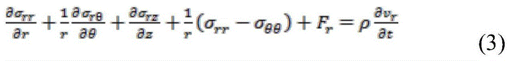

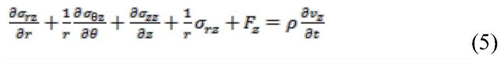
Further considerations regarding our issues may allow for significant simplification. First, we recognize that only physical force is the applied ultrasonic radiation force. Assuming the force is entirely along the z-direction, F can be listed θ =F r And =0. Assuming that the test chamber and applied radiation force are completely axisymmetric, all relationships may be listed based on θ being equal to zero. Applying these simplifications to equations 3 through 5 yields:

0=0 (7)

we follow a similar strategy to develop equation 2, resulting in:

aggregating equations 6 through 9 yields:


the above mathematical formula can be numerically implemented using an interleaved grid method as shown in fig. 15. Each calculation cycle consists of two steps. In the first step, the velocity component is calculated using the above-described finite difference equation. In the next step, shear is calculated using the finite difference equation.
Example-analytical modeling of pulse induced resonance
The exemplary analytical model derived below represents a mechanical model of blood clot displacement in a cylindrical resonant chamber. The model qualitatively captures the behavior observed in real-world experiments.
Our analysis is based on the well-known Cauchy-Navier equation for linear elasticity. We use a formula that combines the properties of viscoelastic materials.

In our initial experiments, a cylindrical test volume was used, where the radiation force was applied to a cylindrical volume of smaller radius having the same central axis as the test volume. This geometry ensures that the angle parameters do not change. We also assume infinite length, which further simplifies the problem by eliminating the variation in range. We apply these simplifications to the components of (16):

due to the cylindrical symmetry and infinite length, we can assume that all derivatives about φ and z are equal to zero. Therefore, (17) becomes:

we now take the gradient to give:

we again recognize that all derivatives with respect to phi and z are equal to zero. Therefore, (19) can be simplified to:

we consider another component of (16):

we again recognize that all derivatives with respect to phi and z are equal to zero. Furthermore, the displacement component with respect to φ is also equal to zero. Therefore, (21) is simplified as:

we expand the laplacian to yield:

we again recognize that the derivatives with respect to phi and z are equal to zero. Therefore, (23) becomes:

(16) The partial differential equation of (a) can be divided into three different equations; one for each direction. We start considering the results in the z direction. Note that the displacement in the z direction is only a function of r and t, since the dependence of Φ and z is eliminated by the radial symmetry and infinite length of the model:

substituting (20) and (24) into (25) yields:

the unfolding (26) yields:

by simplification further we have:

note that (28) does not include dependence on radial displacement. Thus, the underlying system of partial differential equations becomes a single partial differential equation.
Oscillating force:
we solve equation 28 by considering the solution of the following equation, where the displacement is oscillatory.
u z (r,t)=S(r)e jωt (29)
We further assume that the force is also oscillating.
F z (r,t)=F(r)e jωt (30)
Substituting (29) into (28) yields:
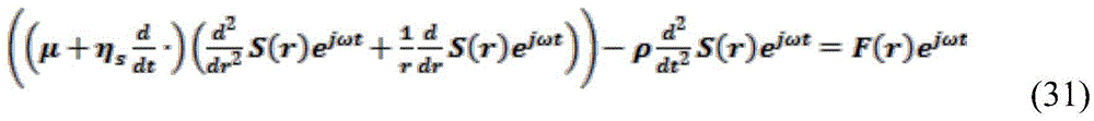
evaluating the derivative with respect to time yields:
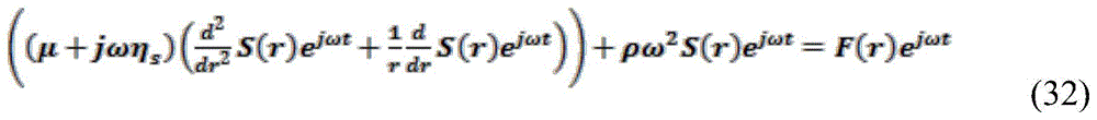
we will go through (3)2) Occurrence of e jωt Putting items on one side gives:

to simplify the notation, we will be (μ + j ω η) s ) Replacement with the general complex shear modulus G, so that (33) becomes:

the solution to this equation depends on the exact form of the forcing function. One simple form assumes a certain transmit beam radius r tx There is a constant force F inside and a force of 0 outside the radius. The solution to this simple forcing function has two fields, one inside the radius rtx and one outside the radius. The solution is:


wherein J 0 Is a zero order Bessel function of the first kind, and Y 0 Is a second class of zero-order Bessel functions. Considering our boundary conditions, we can further simplify this solution. The derivative of the solution is first 0 when r =0. Due to Y 0 There is no finite derivative at 0, so we know c 2 And =0. The following solutions are thus obtained:


it is noted that in order to simplify the notation we will already refer Is replaced by A. We now solve for the arbitrary constants by considering the boundary conditions and continuity conditions of the problem. We assume that the clot adheres rigidly to the chamber wall and thus S 2 (R) =0, wherein R is the radius of the assay chamber. Furthermore, the two solutions must be continuous at their junction, so that S 1 (r b )=S 2 (r b ). Finally, the two solutions must have a continuous derivative at their junction, such that S 1 ′(r b )=S 2 ′(r b ). We can express these three conditions as follows:
c 3 J 0 (AR)+c 4 Y 0 (AR)=0

c 1 J 0 ′(Ar b )-c 3 J 0 ′(Ar b )-c 4 Y 0 ′(Ar b )=0 (37)
recognition of J' 0 (Ar)=-AJ 1 (Ar) and Y' 0 (Ar)=-AY 1 (Ar) and reformulating the above expression into a single system of linear equations yields:

this system of equations can be solved using gaussian elimination. We are primarily concerned with the force application region where r ≦ rt x . Thus, the coefficient of most interest is c 1 . To c 1 And solving to obtain:


the above expressions provide a strict solution to the analytical formulae presented herein. Unfortunately, these rigorous solutions are prone to numerical instability as the operands of the Bessel function become large. In these cases, the numerical error in the Bessel function evaluation is enhanced by subtraction such that c 1 、c 3 And c 4 The evaluation of (2) may be invalid.
The numerical instability of (39), (40) and (41) can be reduced by using simpler expressions for Bessel functions with larger operands. We use the following simplification with respect to large operands.


By applying these expressions to equations 39 through 41, and then using trigonometric identities, c can be reformulated 1 、c 3 And c 4 Making them numerically stable. Note that this reformulation is only valid for large operands, so it must be employed between the two expressionsA conversion determined empirically.
The received signal is a weighted sum of the signals received from each torus within the receive beam. In form, the signal may be considered to be complex exponential and the resulting sum is complex exponential, which is then analyzed to determine the displacement. Since a small displacement makes the first term of the taylor series a reasonable approximation to the complex exponent (cos (x) ≈ 1 and (sin (x) ≈ x), the complex exponent may be ignored, so that the estimated displacement approximates the sum of the displacements on the torus.
Thus, the estimated displacement is a weighted sum of the actual displacements over the axially symmetric region. If the effective receive beam radius is less than the transmit beam radius, then the estimated displacement is:

in the prior art are known In this case, the integral of (46) can be easily calculated.

However, if the receive beam is larger than the transmit beam, the solution takes the form:


displacement due to oscillating forces from the beamlets:
in some cases, it is useful to account for oscillatory displacements in the limits of the very small ultrasound beam. When r is tx Near zero, we will consider equation 36 in the limit.


We recognize that dependence on r b Is a constant, c 1 . Therefore, when r b When it reaches zero, we get c 1 The limit of (c).


Thus, the displacement is equal to:

we further simplify by considering the displacement at the center, i.e. the beam position:

wherein
By examining this expression, we recognize that the displacement will be the largest, i.e., when J is 0 (AR) =0, the system is in resonance. At J 0 (2.4048) the second occurrenceOne zero. Thus, the resonance frequency can be solved as follows:


constant force:
The above analysis is only valid for oscillating forces. In the static case, i.e. the force remains constant over time, we have to perform a separate analysis. We begin with reconsidering equation (28), which is copied below for clarity

Since we are particularly interested in static or direct current problems, we eliminate all derivatives with respect to t, since they must equal zero. We also change the symbolic representation, indicating that we are considering the static shear modulus,

as with the oscillation problem, the solution to this equation depends on the exact form of the forcing function. One simple form assumes a certain transmit beam radius r tx There is a constant force F inside and a force of 0 outside the radius. The solution to this simple forcing function has two fields, one at radius r tx Inner, one is outside the radius. The solution is:


we now solve for the arbitrary constants by considering the boundary conditions and continuity conditions of the problem. We assume that the clot adheres rigidly to the chamber wall and thus S 2 (R) =0, where R is the radius of the assay chamber. Furthermore, the two solutions must be continuous at their junction, so that S 1 (r b )=S 2 (r b ). Finally, the two solutions must have a continuous derivative at their junction, such that S 1 ′(r b )=S 2 ′(r b ). Instead of the analysis used for the repetitive oscillation solution, we propose the following solution:


the estimated displacement is the average of the actual displacements on the receive beams. If the effective receive beam radius is less than the transmit beam radius, then the estimated displacement is:

the integral of (47) is easily calculated.

However, if the receive beam is larger than the transmit beam, the solution takes the form:


viscoelastic tissue model:
Successful application of the proposed model requires selection of an appropriate viscoelastic model, as achieved by the complex frequency dependent shear modulus G. We have studied the Kelvin-Voigt model (Example 1) and the Jeffrey model (Example 2). The Kelvin-Voigt model is generally well suited to modeling clot behavior, but it does not capture some of the porous elastic behavior that may be observed in blood clots. In this sense, the Jeffrey model is sometimes more ideal.
Kelvin-Voigt model G = μ + j ω η exemplifies 1
Jeffrey model Example 2
While specific embodiments have been described in detail in the foregoing detailed description and illustrated in the accompanying drawings, it will be appreciated by those skilled in the art that various modifications and alternatives to those details could be developed in light of the overall teachings of the disclosure and the broad inventive concepts thereof. It is understood, therefore, that the scope of this disclosure is not limited to the particular embodiments and implementations disclosed herein, but is intended to cover modifications within the spirit and scope as defined by the appended claims and any and all equivalents thereof.
Claims (48)
1. A device for assessing hemostasis, the device being usable with a coagulation measurement system to measure at least one viscoelasticity of a blood test sample, comprising:
a housing; and
a plurality of test chambers, each test chamber including a resonant portion, wherein each of the plurality of test chambers is at least partially defined by the housing, wherein each of the plurality of test chambers is each designed to hold a blood test sample combined with a reagent or combination of reagents and to be interrogated by a coagulation measurement system to determine a plurality of hemostasis parameters of the test sample,
wherein each resonant portion of one of the plurality of test chambers is configured to resonate from one or more acoustic pulses directed into the test chamber by the coagulation measurement system.
2. The apparatus of claim 1, wherein each resonant portion of the test chamber comprises a cylindrical region or can be modeled as a cylinder to produce resonance.
3. The apparatus of claim 2, wherein the cylindrical region has a diameter, and wherein the cylindrical region has a length that terminates in a cap having the same diameter.
4. The apparatus of claim 3, wherein the lid is hemispherical or can be modeled as hemispherical.
5. The apparatus of claim 3, wherein an axis of the cylindrical region is aligned with an axis of the cover.
6. The apparatus of claim 3, wherein the cylindrical region is 4.2mm in diameter and 1.5mm in length.
7. The apparatus of claim 1, wherein each of the plurality of test chambers comprises a non-resonant portion having a varying diameter greater than a diameter of the resonant portion.
8. The apparatus of claim 1, wherein the resonance section generates ultrasound induced resonance from applied one or more acoustic pulses, wherein the applied one or more acoustic pulses are transmitted as a plurality of pulse groups, wherein each of the pulse groups is transmitted at a frequency range between 2kHz to 16 kHz.
9. Apparatus according to claim 1, wherein each resonant section is configured to generate a shear wave that is axisymmetric with respect to the applied acoustic radiation force portion, said applied acoustic radiation force being acted on by the applied acoustic pulse or pulses.
10. The apparatus of claim 8, wherein the applied one or more acoustic pulses are directed through a test sample held within a test chamber, and wherein the test chamber has an axisymmetric portion and has a major axis that is collinear with a propagation vector of the applied one or more acoustic pulses.
11. The apparatus of claim 1, wherein the assay chamber is axisymmetric.
12. The apparatus of claim 8, comprising:
an ultrasonic couplant for transmission into and return from at least one of said plurality of test chambers of propagation of said applied one or more acoustic pulses.
13. The apparatus of claim 1, comprising:
a focusing element configured to focus the applied one or more acoustic pulses transmitted into and back from at least one of the plurality of test chambers.
14. The apparatus of claim 13, wherein the focusing element forms a portion of a given one of the plurality of test chambers.
15. The apparatus of claim 14, wherein a portion of the given test chamber of the plurality of test chambers is formed from a coupling agent coupled to the focusing element.
16. The apparatus of claim 13, wherein the focusing element has a refractive shape.
17. The apparatus of claim 13, wherein the applied one or more acoustic pulses comprise ultrasound waves, and wherein the focusing element has a curvature that focuses ultrasound waves directed therethrough.
18. The device of claim 1, wherein an interior surface of one or more of the plurality of test chambers is formed or treated to promote adhesion of a blood clot being formed.
19. The apparatus of claim 1, comprising:
an alignment feature associated with alignment of the device with one or more transducers of the coagulation measurement system.
20. The apparatus of claim 19, further comprising:
a chamber alignment feature associated with alignment of the plurality of test chambers, wherein the transducer alignment feature and the chamber alignment feature mate together to align the one or more transducers with the plurality of test chambers.
21. The device of claim 1, wherein the device is receivable by the coagulation measurement system, and wherein the coagulation measurement system comprises a transducer assembly configured to transmit the one or more acoustic pulses into the plurality of test chambers and receive reflected acoustic pulses from the plurality of test chambers.
22. The device of claim 21, wherein the coagulation measurement system is configured to hold the device in a fixed position relative to the transducer assembly.
23. The apparatus of claim 1, wherein shear modulus is measured over time from interrogation of the plurality of test chambers by the coagulation measurement system.
24. The apparatus of claim 23, wherein the shear modulus of at least one test chamber is estimated by analyzing the resonance of ultrasound induced shear waves generated within the test chamber.
25. The device of claim 1, wherein assessing hemostasis comprises an assessment of coagulation factors including initiation of coagulation, formation of fibrin network, platelet regulatory factor, clot lysis.
26. The apparatus of claim 1, wherein the resonant portion causes induced shear waves to repeatedly reflect at a plurality of walls defining a plurality of portions of the resonant portion to create resonance in the resonant portion.
27. The device of claim 1, wherein the housing is configured as a consumable cartridge.
28. The apparatus of claim 1, wherein the test sample comprises clotted blood.
29. A device for assessing hemostasis, the device being usable with a coagulation measurement system to measure at least one viscoelasticity of a blood test sample, the device comprising:
a housing; and
a plurality of test chambers, each test chamber including a resonating portion, wherein each of the plurality of test chambers is at least partially defined by the housing, wherein each of the plurality of test chambers is each designed to hold a blood test sample combined with a reagent or combination of reagents and to be interrogated by a coagulation measurement system to determine a plurality of hemostasis parameters of the test sample,
wherein each resonant portion of one of the plurality of test chambers is configured to resonate by a forcing waveform comprising one or more acoustic pulses directed into the test chamber by the coagulation measurement system, wherein the resulting resonance is interrogatable by one or more sensing waveforms for estimating a modulus of a clot formed by a sample in the test chamber.
30. The apparatus of claim 29 wherein said forcing waveform carries sufficient energy such that its absorption and reflection within the test sample generates an acoustic radiation force.
31. The device of claim 30, wherein the generated acoustic radiation force is induced along a direction of propagation of the one or more acoustic pulses.
32. The apparatus of claim 30, wherein the generated acoustic radiation force induces shear waves that travel within the test chamber and reflect from one or more walls of the test chamber.
33. The apparatus of claim 32, wherein a single reflected shear wave is detected by the coagulation measurement system and its time of arrival is used as a basis for estimating the modulus of the clot formed by the sample in the test chamber.
34. The apparatus of claim 29, wherein each of the one or more sensing waveforms has a magnitude sufficient to return an ultrasound echo but insufficient to induce a shear wave.
35. The apparatus of claim 29, wherein the coagulation measurement system estimates a shear modulus value for the modulus of the clot formed by the sample in the test chamber.
36. The apparatus of claim 29, wherein the coagulation measurement system estimates a young's modulus value or a Lam constant value for the modulus of the clot formed by the sample in the assay chamber.
37. The device of claim 29, further comprising a focusing element configured to focus an ultrasound waveform into the resonant portion.
38. A system for characterizing mechanical properties of a sample, comprising:
a housing configured to receive a cartridge having a plurality of resonance chambers each configured to hold a test sample, wherein each resonance portion of the plurality of resonance chambers is configured to resonate from a forcing waveform comprising one or more acoustic pulses directed into the resonance chamber;
a transmitter configured to transmit a plurality of waveforms, the plurality of waveforms including at least one forcing waveform and at least one sensing waveform of the forcing waveforms;
a transducer assembly operably connected to the transmitter and configured to convert the transmit waveform into an ultrasonic waveform, the transducer assembly further configured to transmit and receive the ultrasonic waveform into and out of the resonance chamber, and the transducer assembly further configured to convert at least two received sense waveforms into received electrical waveforms;
a data processor configured to:
receiving the received electrical waveform;
estimating resonance of the test sample from the received electrical waveform;
determining a modulus value associated with a stiffness of a clot formed by the resonant sample based on the estimated resonance; and
a controller configured to control timing of the transmitter and the data processor.
39. The system of claim 38, wherein the forcing waveform carries sufficient energy such that its absorption and reflection within the test sample generates an acoustic radiation force.
40. The system of claim 38, wherein the generated acoustic radiation force is induced along a direction of propagation of the one or more acoustic pulses.
41. A system according to claim 39, wherein the generated acoustic radiation forces induce shear waves that travel within the resonant chamber and reflect from one or more walls of the resonant chamber.
42. A system according to claim 41, wherein a single reflected shear wave is detected by the transducer assembly and its time of arrival is used as a basis for estimating the modulus of the clot formed by the sample in the resonance chamber.
43. The system of claim 38, wherein each of the one or more sensing waveforms has a magnitude sufficient to return an ultrasound echo but insufficient to induce a shear wave.
44. The system of claim 38, wherein the data processor is configured to estimate a shear modulus value for a modulus of the clot formed by a sample in the resonance chamber.
45. The system of claim 38, wherein the data processor is configured to estimate a young's modulus value or a Lam constant value for a modulus of the clot formed by a sample in the resonance chamber.
46. The system of claim 38, wherein the data processor is configured to determine a modulus value associated with a stiffness of a clot formed by the resonant sample by comparing the estimated resonance to a reference model derived from a parameter associated with the forcing waveform and a parameter associated with the resonant chamber.
47. The system of claim 46, wherein the reference model comprises a plurality of curves each having a set of time-displacement curves associated with a given modulus value.
48. The system according to claim 38, wherein the data processor is configured to determine a modulus value associated with a stiffness of a clot formed by the resonant sample by comparing the estimated resonance to an experimentally derived model associated with a stiffness of a clot formed by the resonant sample.
Applications Claiming Priority (4)
| Application Number | Priority Date | Filing Date | Title |
|---|---|---|---|
| US14/660,700 US9726647B2 (en) | 2015-03-17 | 2015-03-17 | Determining mechanical properties via ultrasound-induced resonance |
| US14/660,700 | 2015-03-17 | ||
| CN201680015219.6A CN107430093B (en) | 2015-03-17 | 2016-03-17 | Determination of Mechanical Properties via Ultrasound Induced Resonance |
| PCT/US2016/022844 WO2016149480A1 (en) | 2015-03-17 | 2016-03-17 | Determining mechanical properties via ultrasound-induced resonance |
Related Parent Applications (1)
| Application Number | Title | Priority Date | Filing Date |
|---|---|---|---|
| CN201680015219.6A Division CN107430093B (en) | 2015-03-17 | 2016-03-17 | Determination of Mechanical Properties via Ultrasound Induced Resonance |
Publications (2)
| Publication Number | Publication Date |
|---|---|
| CN109884184A CN109884184A (en) | 2019-06-14 |
| CN109884184B true CN109884184B (en) | 2022-11-18 |
Family
ID=56919432
Family Applications (3)
| Application Number | Title | Priority Date | Filing Date |
|---|---|---|---|
| CN201680015219.6A Active CN107430093B (en) | 2015-03-17 | 2016-03-17 | Determination of Mechanical Properties via Ultrasound Induced Resonance |
| CN201910203968.7A Active CN109884184B (en) | 2015-03-17 | 2016-03-17 | Device for assessing haemostasis |
| CN202211120511.8A Active CN115436468B (en) | 2015-03-17 | 2016-03-17 | Methods for assessing hemostatic function |
Family Applications Before (1)
| Application Number | Title | Priority Date | Filing Date |
|---|---|---|---|
| CN201680015219.6A Active CN107430093B (en) | 2015-03-17 | 2016-03-17 | Determination of Mechanical Properties via Ultrasound Induced Resonance |
Family Applications After (1)
| Application Number | Title | Priority Date | Filing Date |
|---|---|---|---|
| CN202211120511.8A Active CN115436468B (en) | 2015-03-17 | 2016-03-17 | Methods for assessing hemostatic function |
Country Status (7)
| Country | Link |
|---|---|
| US (6) | US9726647B2 (en) |
| EP (2) | EP3271714B1 (en) |
| CN (3) | CN107430093B (en) |
| AU (2) | AU2016233243B2 (en) |
| CA (3) | CA3220504A1 (en) |
| ES (1) | ES3038861T3 (en) |
| WO (1) | WO2016149480A1 (en) |
Families Citing this family (37)
| Publication number | Priority date | Publication date | Assignee | Title |
|---|---|---|---|---|
| US9726647B2 (en) | 2015-03-17 | 2017-08-08 | Hemosonics, Llc | Determining mechanical properties via ultrasound-induced resonance |
| US10660604B2 (en) | 2015-07-13 | 2020-05-26 | Otonexus Medical Technologies, Inc. | Apparatus and method for characterization of acute otitis media |
| US10376233B2 (en) * | 2016-04-08 | 2019-08-13 | Siemens Medical Solutions Usa, Inc. | Diffraction source compensation in medical diagnostic ultrasound viscoelastic imaging |
| US11064979B2 (en) * | 2016-05-16 | 2021-07-20 | Analogic Corporation | Real-time anatomically based deformation mapping and correction |
| US12178651B2 (en) | 2016-05-16 | 2024-12-31 | Bk Medical Holding Company, Inc. | Real-time anatomically based deformation mapping and correction |
| US10675001B2 (en) | 2016-06-04 | 2020-06-09 | Otonexus Medical Technologies, Inc. | Apparatus and method for characterization of a ductile membrane, surface, and sub-surface properties |
| US12029525B2 (en) * | 2016-11-16 | 2024-07-09 | University Of Rochester | Reverberant shear wave field estimation of body properties |
| GB2557345B (en) * | 2016-12-08 | 2021-10-13 | Bae Systems Plc | MIMO communication system and data link |
| US10634646B2 (en) * | 2017-01-20 | 2020-04-28 | GTBM, Inc. | Acoustic frequency based system with crystalline transducer module for non-invasive detection of explosives, contraband, and other elements |
| SE540655C2 (en) * | 2017-03-06 | 2018-10-09 | Bluetest Ab | Arrangement and method for measuring the performance of devices with wireless capability |
| USD839447S1 (en) | 2017-04-20 | 2019-01-29 | Hemosonics Llc | Hemostasis measurement cartridge |
| EP3612838B1 (en) | 2017-04-20 | 2024-09-25 | Hemosonics, LLC | Disposable system for analysis of hemostatic function |
| USD841184S1 (en) | 2017-06-06 | 2019-02-19 | Hemosonics Llc | Transparent hemostasis measurement cartridge |
| WO2018224602A1 (en) * | 2017-06-09 | 2018-12-13 | Technische Universiteit Eindhoven | Shear wave viscoelasticity imaging using local system identification |
| CN107505393A (en) * | 2017-07-21 | 2017-12-22 | 无锡海斯凯尔医学技术有限公司 | The viscoelastic measuring method of medium and device |
| CN107478723A (en) * | 2017-07-21 | 2017-12-15 | 无锡海斯凯尔医学技术有限公司 | The viscoelastic measuring method of medium and device |
| CN107440740B (en) * | 2017-07-21 | 2021-06-25 | 无锡海斯凯尔医学技术有限公司 | Method and device for quantitative viscoelasticity of medium |
| CN107495986A (en) * | 2017-07-21 | 2017-12-22 | 无锡海斯凯尔医学技术有限公司 | The viscoelastic measuring method of medium and device |
| CN107505233A (en) * | 2017-07-21 | 2017-12-22 | 无锡海斯凯尔医学技术有限公司 | Medium viscoplasticity quantitative approach and device |
| US11154277B2 (en) * | 2017-10-31 | 2021-10-26 | Siemens Medical Solutions Usa, Inc. | Tissue viscoelastic estimation from shear velocity in ultrasound medical imaging |
| US11800979B2 (en) * | 2017-12-04 | 2023-10-31 | Bar Ilan University | System and method for calculating a characteristic of a region of interest of an individual |
| US11197962B2 (en) | 2018-02-26 | 2021-12-14 | Verily Life Sciences Llc | Waveform reconstruction for ultrasound time of flight measurements |
| WO2019218141A1 (en) | 2018-05-15 | 2019-11-21 | 深圳迈瑞生物医疗电子股份有限公司 | Shear wave elasticity measurement method and shear wave elastography system |
| WO2020013868A1 (en) * | 2018-07-13 | 2020-01-16 | Otonexus Medical Technologies, Inc. | Apparatus and method for characterization of a ductile membrane, surface and sub-surface properties |
| JP2022519782A (en) | 2019-02-07 | 2022-03-24 | ヴィヴェーク・ケー・シャルマ | Systems and methods for treating cancer cells with alternating polar magnetic fields |
| US11027143B2 (en) | 2020-02-06 | 2021-06-08 | Vivek K. Sharma | System and methods for treating cancer cells with alternating polarity magnetic fields |
| US11344740B2 (en) | 2019-02-07 | 2022-05-31 | Asha Medical, Inc. | System and methods for treating cancer cells with alternating polarity magnetic fields |
| US11053473B2 (en) * | 2019-06-25 | 2021-07-06 | Hemex Health, Inc. | External sonication |
| US11422113B2 (en) * | 2020-06-30 | 2022-08-23 | Apple Inc. | Ultrasonic water-agnostic touch detection sensor |
| EP3971576B1 (en) | 2020-09-21 | 2025-03-19 | Instrumentation Laboratory Company | Detecting and monitoring oral anticoagulants or intravenous direct thrombin inhibitors in a blood sample |
| WO2022109434A1 (en) * | 2020-11-23 | 2022-05-27 | Amgen Inc. | Methods and systems of determining a viscosity of liquid samples |
| US10996163B1 (en) * | 2021-01-12 | 2021-05-04 | Endra Life Sciences Inc. | Acoustically isolated thermoacoustic imaging probe and process of manufacture |
| CN116761546A (en) * | 2021-01-27 | 2023-09-15 | 皇家飞利浦有限公司 | Devices and methods for enhanced interpretation of magnetic resonance and ultrasound shear wave elastography for monitoring liver fibrosis |
| CN113640377B (en) * | 2021-10-15 | 2021-12-14 | 中国科学院苏州生物医学工程技术研究所 | Blood viscoelasticity measuring method based on vibration sensor |
| CN114910132B (en) * | 2022-04-12 | 2025-01-03 | 上海理工大学 | A feature point recognition method based on ultrasonic echo signal contour |
| JP2024064241A (en) * | 2022-10-27 | 2024-05-14 | 富士フイルムヘルスケア株式会社 | Ultrasound diagnostic equipment |
| US12584902B2 (en) | 2023-12-10 | 2026-03-24 | Instrumentation Laboratory Company | Acoustic separation of a test sample |
Family Cites Families (410)
| Publication number | Priority date | Publication date | Assignee | Title |
|---|---|---|---|---|
| US3537541A (en) * | 1968-07-02 | 1970-11-03 | Sinclair Research Inc | Acoustic bomb and transducer apparatus |
| US3720098A (en) * | 1971-03-22 | 1973-03-13 | Atomic Energy Commission | Ultrasonic apparatus and method for nondestructively measuring the physical properties of a sample |
| JPS5311473B2 (en) | 1974-07-03 | 1978-04-21 | ||
| JPS5130683A (en) | 1974-09-10 | 1976-03-16 | Okuma Machinery Works Ltd | NARAISEIGYO SOCHI |
| US3996791A (en) | 1975-04-24 | 1976-12-14 | Krautkramer-Branson, Incorporated | Ultrasonic test method and apparatus utilizing scattered signals |
| US4105018A (en) | 1976-02-02 | 1978-08-08 | University Of Utah | Acoustic examination, material characterization and imaging of the internal structure of a body by measurement of the time-of-flight of acoustic energy therethrough |
| AU505308B2 (en) | 1976-09-21 | 1979-11-15 | Asahi Glass Company Limited | Glass for use in ultrasonic delay lines |
| JPS5655091Y2 (en) | 1976-09-29 | 1981-12-22 | ||
| CH610111A5 (en) | 1977-01-13 | 1979-03-30 | Contraves Ag | |
| JPS541062A (en) | 1977-06-04 | 1979-01-06 | Daikin Ind Ltd | Oil level indicator for oil tank of oil combustion type heating machine |
| JPS541062U (en) | 1977-06-06 | 1979-01-06 | ||
| JPS5563470U (en) | 1978-10-25 | 1980-04-30 | ||
| JPS5563470A (en) | 1978-11-08 | 1980-05-13 | Tokyo Electric Co Ltd | Electronic cash register |
| US4238725A (en) | 1979-01-15 | 1980-12-09 | The United States Of America As Represented By The United States Department Of Energy | Apparatus for checking the direction of polarization of shear-wave ultrasonic transducers |
| US4248092A (en) | 1979-04-25 | 1981-02-03 | Electric Power Research Institute, Inc. | Method and apparatus for efficiently generating elastic waves with a transducer |
| US4293934A (en) | 1979-06-18 | 1981-10-06 | Shell Oil Company | Circumferential acoustic device |
| DE2938254C2 (en) | 1979-09-21 | 1982-04-22 | Siemens AG, 1000 Berlin und 8000 München | Flexible printed circuit |
| JPS5655091U (en) | 1979-10-01 | 1981-05-13 | ||
| US4305294A (en) | 1980-01-10 | 1981-12-15 | Rockwell International Corporation | Ultrasonic apparatus and method for measuring wall thickness |
| JPS56143951A (en) | 1980-04-10 | 1981-11-10 | Nisshin Steel Co Ltd | Ultrasonic flaw detection for austenite alloy steel welded steel pipe |
| US4292848A (en) | 1980-04-11 | 1981-10-06 | Systems Research Laboratories, Inc. | Walking-gate ultrasonic flaw detector |
| US4570487A (en) | 1980-04-21 | 1986-02-18 | Southwest Research Institute | Multibeam satellite-pulse observation technique for characterizing cracks in bimetallic coarse-grained component |
| US4435984A (en) | 1980-04-21 | 1984-03-13 | Southwest Research Institute | Ultrasonic multiple-beam technique for detecting cracks in bimetallic or coarse-grained materials |
| US4484569A (en) * | 1981-03-13 | 1984-11-27 | Riverside Research Institute | Ultrasonic diagnostic and therapeutic transducer assembly and method for using |
| US4900679A (en) | 1983-01-26 | 1990-02-13 | University Of Medicine And Dentistry Of New Jersey | Method for determining the existence and/or the monitoring of a pathological condition in a mammal and a test kit therefor |
| US4814247A (en) | 1983-01-26 | 1989-03-21 | University Of Medicine And Dentistry Of New Jersey | Method for determining the existance and/or the monitoring of a pathological condition in a mammal |
| US4705756A (en) | 1983-01-26 | 1987-11-10 | University Of Medicine And Dentistry Of New Jersey | Method of determining the existence and/or the monitoring of a pathological condition in a mammal |
| US4522064A (en) | 1983-12-12 | 1985-06-11 | Sigma Research Inc. | Ultrasonic method and apparatus for determining the depth of a crack in a solid material |
| US4598973A (en) | 1984-03-07 | 1986-07-08 | Greenleaf James F | Apparatus and method for recording and displaying a three-dimensional image |
| US4559827A (en) | 1984-04-11 | 1985-12-24 | The United States Of America As Represented By The United States Department Of Energy | Ultrasonic shear wave couplant |
| JPS6193952A (en) | 1984-10-04 | 1986-05-12 | Mitsubishi Electric Corp | Ultrasonic angle flaw detection method for thick-walled pipes |
| US4558589A (en) | 1984-10-09 | 1985-12-17 | Miles Laboratories, Inc. | Ultrasonic coagulation monitor and method |
| US4695956A (en) | 1984-11-01 | 1987-09-22 | Leveen Eric G | Apparatus and method of quantifying hemostasis using oscillations from a transducer immersed in the blood sample |
| US4658827A (en) | 1985-05-31 | 1987-04-21 | Mayo Medical Resources | Ultrasound scanner for tissue characterization |
| US4658649A (en) | 1985-06-06 | 1987-04-21 | Combustion Engineering, Inc. | Ultrasonic method and device for detecting and measuring defects in metal media |
| US4702110A (en) | 1985-06-20 | 1987-10-27 | J. A. Green Company | Method and apparatus for measuring metal hardness utilizing longitudinal and transverse ultrasonic wave time-of-flight |
| US4641531A (en) | 1986-03-27 | 1987-02-10 | Reeves Roger D | Ultrasonic inspection apparatus and method for locating multiple defects in eccentric wall tubular goods |
| US4735096A (en) | 1986-08-27 | 1988-04-05 | Xecutek Corporation | Ultrasonic transducer |
| GB8623435D0 (en) | 1986-09-30 | 1986-11-05 | Squire P T | Magnetic field sensor |
| US4806070A (en) | 1987-04-13 | 1989-02-21 | General Electric Company | Article transfer apparatus |
| SE8704255L (en) | 1987-11-02 | 1989-05-03 | Hans W Persson | ACOUSTIC METHOD FOR SEATING CHARACTERISTICS OF A MOVABLE MEDIUM |
| US4829430A (en) | 1987-11-13 | 1989-05-09 | Mayo Foundation For Medical Education And Research | Method for reducing artifacts in ultrasound backscatter tomography |
| YU47190B (en) | 1988-02-19 | 1995-01-31 | Institut Za Opštu I Fizičku Hemiju | DEVICE FOR NON-INVASIVE ACOUSTIC TESTING OF ELASTICITY OF SOFT BIOLOGICAL MATERIALS |
| US5115808A (en) | 1988-02-19 | 1992-05-26 | Institute Of General And Physical Chemistry | Method and device for noninvasive acoustic testing of elasticity of soft biological tissues |
| US4852577A (en) | 1988-04-07 | 1989-08-01 | The United States Of America As Represented By The Department Of Health And Human Services | High speed adaptive ultrasonic phased array imaging system |
| US5104975A (en) | 1988-07-08 | 1992-04-14 | Cetus Corporation | Compositions for detecting ras gene proteins and cancer therapeutics |
| US5234839A (en) | 1988-07-08 | 1993-08-10 | Cetus Oncology Corporation | Compositions for detecting ras gene proteins and cancer therapeutics |
| US5038787A (en) | 1988-08-10 | 1991-08-13 | The Board Of Regents, The University Of Texas System | Method and apparatus for analyzing material properties using reflected ultrasound |
| GB2232487B (en) | 1989-06-09 | 1993-08-04 | Shimizu Construction Co Ltd | Ultrasonic measuring apparatus including a high-damping probe |
| US5016469A (en) | 1989-09-29 | 1991-05-21 | Sienco, Inc. | Fluid viscoelastic test apparatus and method |
| US5007291A (en) | 1989-10-05 | 1991-04-16 | Scan Systems, Inc. | Ultrasonic inspection apparatus with centering means for tubular members |
| US5081995A (en) | 1990-01-29 | 1992-01-21 | Mayo Foundation For Medical Education And Research | Ultrasonic nondiffracting transducer |
| US5082418A (en) | 1990-03-26 | 1992-01-21 | Thomson Consumer Electronics, Inc. | System for automatically loading and unloading articles coupled by cabling |
| US5086775A (en) * | 1990-11-02 | 1992-02-11 | University Of Rochester | Method and apparatus for using Doppler modulation parameters for estimation of vibration amplitude |
| US6432236B1 (en) | 1991-03-01 | 2002-08-13 | Foster-Miller, Inc. | Ultrasonic method of fabricating a thermosetting matrix fiber-reinforced composite structure and the product thereof |
| US5408882A (en) | 1991-06-24 | 1995-04-25 | General Electric Company | Ultrasonic device and method for non-destructive evaluation of polymer composites |
| US5273517A (en) | 1991-07-09 | 1993-12-28 | Haemonetics Corporation | Blood processing method and apparatus with disposable cassette |
| US6114135A (en) | 1991-11-08 | 2000-09-05 | Goldstein; Sheldon | Multiple coagulation test system and method of using a multiple coagulation test system |
| US7497828B1 (en) | 1992-01-10 | 2009-03-03 | Wilk Ultrasound Of Canada, Inc. | Ultrasonic medical device and associated method |
| US5205159A (en) | 1992-01-17 | 1993-04-27 | Virginia Commonwealth University | Apparatus and method for measuring clot elastic modulus and force development on the same blood sample |
| US5993389A (en) | 1995-05-22 | 1999-11-30 | Ths International, Inc. | Devices for providing acoustic hemostasis |
| US5744898A (en) | 1992-05-14 | 1998-04-28 | Duke University | Ultrasound transducer array with transmitter/receiver integrated circuitry |
| RU2061218C1 (en) | 1992-07-22 | 1996-05-27 | Всероссийский научно-исследовательский институт природных газов и газовых технологий | Device for determination of properties of fluid media |
| US5860934A (en) | 1992-12-21 | 1999-01-19 | Artann Corporation | Method and device for mechanical imaging of breast |
| US5922018A (en) | 1992-12-21 | 1999-07-13 | Artann Corporation | Method for using a transrectal probe to mechanically image the prostate gland |
| US5836894A (en) | 1992-12-21 | 1998-11-17 | Artann Laboratories | Apparatus for measuring mechanical parameters of the prostate and for imaging the prostate using such parameters |
| US5524636A (en) | 1992-12-21 | 1996-06-11 | Artann Corporation Dba Artann Laboratories | Method and apparatus for elasticity imaging |
| US5678565A (en) | 1992-12-21 | 1997-10-21 | Artann Corporation | Ultrasonic elasticity imaging method and device |
| US5265612A (en) | 1992-12-21 | 1993-11-30 | Medical Biophysics International | Intracavity ultrasonic device for elasticity imaging |
| US6142959A (en) | 1992-12-21 | 2000-11-07 | Armed L.L.C. | Device for palpation and mechanical imaging of the prostate |
| US5785663A (en) | 1992-12-21 | 1998-07-28 | Artann Corporation | Method and device for mechanical imaging of prostate |
| US5331964A (en) | 1993-05-14 | 1994-07-26 | Duke University | Ultrasonic phased array imaging system with high speed adaptive processing using selected elements |
| US5469743A (en) | 1993-06-24 | 1995-11-28 | Zorn; Roger H. | Dynamic surface wave roll inspection device |
| CA2175232A1 (en) | 1993-10-29 | 1995-05-04 | Vladimir Belonenko | Method and system for measuring fluid parameters by ultrasonic methods |
| US5614670A (en) | 1993-10-29 | 1997-03-25 | Board Of Regents, The University Of Texas System | Movable seismic pavement analyzer |
| US5473536A (en) | 1994-04-04 | 1995-12-05 | Spacelabs Medical, Inc. | Method and system for customizing the display of patient physiological parameters on a medical monitor |
| US5431054A (en) | 1994-04-07 | 1995-07-11 | Reeves; R. Dale | Ultrasonic flaw detection device |
| AU2373695A (en) | 1994-05-03 | 1995-11-29 | Board Of Regents, The University Of Texas System | Apparatus and method for noninvasive doppler ultrasound-guided real-time control of tissue damage in thermal therapy |
| US5533402A (en) | 1994-05-11 | 1996-07-09 | Artann Corporation | Method and apparatus for measuring acoustic parameters in liquids using cylindrical ultrasonic standing waves |
| US5487387A (en) | 1994-06-03 | 1996-01-30 | Duke University | Method and apparatus for distinguishing between solid masses and fluid-filled cysts |
| US5474225A (en) | 1994-07-18 | 1995-12-12 | The Babcock & Wilcox Company | Automated method for butt weld inspection and defect diagnosis |
| US5439157A (en) | 1994-07-18 | 1995-08-08 | The Babcock & Wilcox Company | Automated butt weld inspection system |
| WO1996002831A1 (en) | 1994-07-18 | 1996-02-01 | The Babcock & Wilcox Company | Sensor transport system for flash butt welder |
| US5714688A (en) | 1994-09-30 | 1998-02-03 | The Babcock & Wilcox Company | EMAT measurement of ductile cast iron nodularity |
| US5504011A (en) | 1994-10-21 | 1996-04-02 | International Technidyne Corporation | Portable test apparatus and associated method of performing a blood coagulation test |
| US5899861A (en) | 1995-03-31 | 1999-05-04 | Siemens Medical Systems, Inc. | 3-dimensional volume by aggregating ultrasound fields of view |
| US5655535A (en) | 1996-03-29 | 1997-08-12 | Siemens Medical Systems, Inc. | 3-Dimensional compound ultrasound field of view |
| GB9510032D0 (en) | 1995-05-18 | 1995-07-12 | Atomic Energy Authority Uk | Ultrasonic inspection |
| US5605154A (en) | 1995-06-06 | 1997-02-25 | Duke University | Two-dimensional phase correction using a deformable ultrasonic transducer array |
| US6898532B1 (en) * | 1995-06-07 | 2005-05-24 | Biomerieux, Inc. | Method and apparatus for predicting the presence of haemostatic dysfunction in a patient sample |
| JPH11513280A (en) | 1995-09-27 | 1999-11-16 | アータン・ラボラトリーズ | Measurement of mechanical properties of tissue anisotropy |
| US5810731A (en) | 1995-11-13 | 1998-09-22 | Artann Laboratories | Method and apparatus for elasticity imaging using remotely induced shear wave |
| US5606971A (en) | 1995-11-13 | 1997-03-04 | Artann Corporation, A Nj Corp. | Method and device for shear wave elasticity imaging |
| US5854423A (en) | 1996-03-20 | 1998-12-29 | Venegas; Jose G. | Apparatus and method for assessment of visco-elasticity and shear adherence strength properties of blood clots |
| US5991239A (en) | 1996-05-08 | 1999-11-23 | Mayo Foundation For Medical Education And Research | Confocal acoustic force generator |
| US5903516A (en) | 1996-05-08 | 1999-05-11 | Mayo Foundation For Medical Education And Research | Acoustic force generator for detection, imaging and information transmission using the beat signal of multiple intersecting sonic beams |
| US5673699A (en) | 1996-05-31 | 1997-10-07 | Duke University | Method and apparatus for abberation correction in the presence of a distributed aberrator |
| DE69710725T2 (en) | 1996-07-02 | 2002-11-21 | B-K Medical A/S, Gentofte | DEVICE FOR DETERMINING MOVEMENTS AND SPEEDS OF MOVING OBJECTS |
| US5681996A (en) | 1996-08-01 | 1997-10-28 | Beloit Technologies, Inc. | Ultrasonic device for inspection of metal parts |
| US5952578A (en) | 1996-08-01 | 1999-09-14 | Beloit Technoloiges, Inc. | Ultrasonic examination of coated parts |
| US6424852B1 (en) | 1996-10-18 | 2002-07-23 | Lucid, Inc. | System for confocal imaging within dermal tissue |
| EP0839497A1 (en) | 1996-11-01 | 1998-05-06 | EndoSonics Corporation | A method for measuring volumetric fluid flow and its velocity profile in a lumen or other body cavity |
| US5921928A (en) | 1996-12-05 | 1999-07-13 | Mayo Foundation For Medical Education And Research | Acoustic force generation by amplitude modulating a sonic beam |
| US5720708A (en) | 1997-01-02 | 1998-02-24 | Mayo Foundation For Medical Education And Research | High frame rate imaging with limited diffraction beams |
| US6110120A (en) * | 1997-04-11 | 2000-08-29 | Acuson Corporation | Gated ultrasound imaging apparatus and method |
| IL120830A0 (en) | 1997-05-14 | 1997-09-30 | Irt Inspection Res & Tech | A device for ultrasonic inspection of a multi-layer metal workpiece |
| EP1006881A4 (en) | 1997-06-02 | 2004-04-28 | Univ Duke | DEVICE AND METHOD FOR CINETIC ACOUSTIC EYE EXAMINATION |
| US20010053384A1 (en) | 1997-07-07 | 2001-12-20 | James F. Greenleaf | Site-directed transfection with ultrasound and cavitation nuclei |
| ZA985834B (en) | 1997-07-21 | 1999-01-14 | Henkel Corp | Method for reinforcing structural members |
| US6016701A (en) | 1997-12-09 | 2000-01-25 | Siemens Power Corporation | Ultrasonic inspection system |
| GB9800813D0 (en) | 1998-01-16 | 1998-03-11 | Andaris Ltd | Improved ultrasound contrast imaging method and apparatus |
| DE19812285A1 (en) | 1998-03-20 | 1999-09-23 | Philips Patentverwaltung | Imaging procedure for medical examinations |
| US6385474B1 (en) | 1999-03-19 | 2002-05-07 | Barbara Ann Karmanos Cancer Institute | Method and apparatus for high-resolution detection and characterization of medical pathologies |
| US6270459B1 (en) | 1998-05-26 | 2001-08-07 | The Board Of Regents Of The University Of Texas System | Method for estimating and imaging of transverse displacements, transverse strains and strain ratios |
| DE19824108A1 (en) | 1998-05-29 | 1999-12-02 | Andreas Pesavento | A system for the rapid calculation of strain images from high-frequency ultrasound echo signals |
| US20030078227A1 (en) | 1998-07-02 | 2003-04-24 | Greenleaf James F. | Site-directed transfection with ultrasound and cavitation nuclei |
| US6117081A (en) | 1998-10-01 | 2000-09-12 | Atl Ultrasound, Inc. | Method for correcting blurring of spatially compounded ultrasonic diagnostic images |
| US6283917B1 (en) | 1998-10-01 | 2001-09-04 | Atl Ultrasound | Ultrasonic diagnostic imaging system with blurring corrected spatial compounding |
| US6277074B1 (en) | 1998-10-02 | 2001-08-21 | University Of Kansas Medical Center | Method and apparatus for motion estimation within biological tissue |
| DE102004033595A1 (en) | 2004-07-07 | 2006-02-16 | Celon Ag Medical Instruments | Bipolar coagulation electrode |
| US6246895B1 (en) | 1998-12-18 | 2001-06-12 | Sunnybrook Health Science Centre | Imaging of ultrasonic fields with MRI |
| US6293156B1 (en) | 1999-01-22 | 2001-09-25 | Panametrics, Inc. | Coherent multi-path flow measurement system |
| US7732213B2 (en) | 1999-02-22 | 2010-06-08 | Coramed Healthcare, Inc. | Method of evaluating patient hemostasis |
| US8008086B2 (en) | 1999-02-22 | 2011-08-30 | Cora Healthcare, Inc. | Protocol for monitoring direct thrombin inhibition |
| US7179652B2 (en) | 1999-02-22 | 2007-02-20 | Haemoscope Corporation | Protocol for monitoring platelet inhibition |
| US6613573B1 (en) | 1999-02-22 | 2003-09-02 | Haemoscope Corporation | Method and apparatus for monitoring anti-platelet agents |
| US6797519B2 (en) | 2001-10-10 | 2004-09-28 | Haemoscope Corporation | Method and apparatus for diagnosing hemostasis |
| US6787363B2 (en) | 1999-02-22 | 2004-09-07 | Haemoscope Corporation | Method and apparatus for hemostasis and blood management |
| US6225126B1 (en) | 1999-02-22 | 2001-05-01 | Haemoscope Corporation | Method and apparatus for measuring hemostasis |
| FR2791136B1 (en) | 1999-03-15 | 2001-06-08 | Mathias Fink | IMAGING METHOD AND DEVICE USING SHEAR WAVES |
| US6155117A (en) | 1999-03-18 | 2000-12-05 | Mcdermott Technology, Inc. | Edge detection and seam tracking with EMATs |
| ATE510189T1 (en) | 1999-04-01 | 2011-06-15 | Panametrics | ATTACHABLE ULTRASONIC FLOW METER for LOW DENSITY LIQUIDS |
| US6488626B1 (en) * | 1999-04-07 | 2002-12-03 | Riverside Research Institute | Ultrasonic sensing by induced tissue motion |
| US6068597A (en) | 1999-04-13 | 2000-05-30 | Lin; Gregory Sharat | Vibrational resonance ultrasonic Doppler spectrometer and imager |
| JP5161407B2 (en) | 1999-05-14 | 2013-03-13 | コーニンクレッカ フィリップス エレクトロニクス エヌ ヴィ | Magnetic resonance elastography |
| US6692439B1 (en) | 1999-07-07 | 2004-02-17 | University Of Virginia Patent Foundation | Angular scatter imaging system using translating apertures and method thereof |
| US6340589B1 (en) * | 1999-07-23 | 2002-01-22 | Mj Research, Inc. | Thin-well microplate and methods of making same |
| US7192726B1 (en) | 1999-08-13 | 2007-03-20 | Hemodyne, Inc. | Method of using platelet contractile force and whole blood clot elastic modulus as clinical markers |
| US6264609B1 (en) | 1999-09-15 | 2001-07-24 | Wake Forest University | Ultrasound apparatus and method for tissue characterization |
| US6360610B1 (en) | 1999-11-02 | 2002-03-26 | Jacek Jarzynski | Condition monitoring system and method for an interface |
| US6867535B1 (en) | 1999-11-05 | 2005-03-15 | Sensant Corporation | Method of and apparatus for wafer-scale packaging of surface microfabricated transducers |
| US6412344B1 (en) | 1999-11-15 | 2002-07-02 | Rosemount Aerospace Inc. | Fluid level sensor with dry couplant |
| US6535835B1 (en) | 2000-01-31 | 2003-03-18 | Ge Medical Systems Global Technology Company, Llc | Angle independent ultrasound volume flow measurement |
| US6868289B2 (en) | 2002-10-02 | 2005-03-15 | Standen Ltd. | Apparatus for treating a tumor or the like and articles incorporating the apparatus for treatment of the tumor |
| US8175698B2 (en) | 2000-02-17 | 2012-05-08 | Novocure Ltd. | Treating bacteria with electric fields |
| US7146210B2 (en) | 2000-02-17 | 2006-12-05 | Standen Ltd. | Apparatus and method for optimizing tumor treatment efficiency by electric fields |
| US7016725B2 (en) | 2001-11-06 | 2006-03-21 | Standen Ltd. | Method and apparatus for destroying dividing cells |
| US7333852B2 (en) | 2000-02-17 | 2008-02-19 | Standen Ltd. | Method and apparatus for destroying dividing cells |
| US7136699B2 (en) | 2002-10-02 | 2006-11-14 | Standen, Ltd. | Apparatus for destroying dividing cells |
| US8447395B2 (en) | 2000-02-17 | 2013-05-21 | Novocure Ltd | Treating bacteria with electric fields |
| US7599746B2 (en) | 2000-02-17 | 2009-10-06 | Standen Ltd | Apparatus and method for preventing the spread of cancerous metastases and for elimination of metastases |
| US7089054B2 (en) | 2002-10-02 | 2006-08-08 | Standen Ltd. | Apparatus and method for treating a tumor or the like |
| US6511427B1 (en) | 2000-03-10 | 2003-01-28 | Acuson Corporation | System and method for assessing body-tissue properties using a medical ultrasound transducer probe with a body-tissue parameter measurement mechanism |
| WO2001071366A2 (en) | 2000-03-17 | 2001-09-27 | The Board Of Regents Of The University Of Texas System | Power spectral strain estimators in elastography |
| AU2001253084B2 (en) | 2000-03-30 | 2006-07-06 | Uab Research Foundation | Gated functional muscle imaging |
| US6595933B2 (en) | 2000-03-31 | 2003-07-22 | Artann Laboratories | Self-palpation device for examination of breast with 3-D positioning system |
| US6468231B2 (en) | 2000-03-31 | 2002-10-22 | Artann Laboratories | Self-palpation device for examination of breast |
| US7374538B2 (en) | 2000-04-05 | 2008-05-20 | Duke University | Methods, systems, and computer program products for ultrasound measurements using receive mode parallel processing |
| US6371912B1 (en) | 2000-04-05 | 2002-04-16 | Duke University | Method and apparatus for the identification and characterization of regions of altered stiffness |
| US6402704B1 (en) | 2000-04-18 | 2002-06-11 | Sonexxus Incorporated | Prothrombin test apparatus for home use |
| CN1383374A (en) | 2000-04-26 | 2002-12-04 | 皇家菲利浦电子有限公司 | Ultrasonic method and system for shear wave parameter estimation |
| US6541262B1 (en) | 2000-04-28 | 2003-04-01 | Medtronic, Inc. | Method and device for testing a sample of fresh whole blood |
| US6620115B2 (en) | 2000-04-28 | 2003-09-16 | Armed L.L.C. | Apparatus and method for mechanical imaging of breast |
| IL153860A0 (en) | 2000-07-10 | 2003-07-31 | N D T Instr Ltd | Method and apparatus for determining the composition of fluids |
| US6514204B2 (en) | 2000-07-20 | 2003-02-04 | Riverside Research Institute | Methods for estimating tissue strain |
| US6511429B1 (en) | 2000-08-17 | 2003-01-28 | Mayo Foundation For Medical Education And Research | Ultrasonic methods and systems for reducing fetal stimulation |
| US6851319B2 (en) | 2000-09-27 | 2005-02-08 | Digital Wave Corporation | Device and method designed for ultrasonically inspecting cylinders for longitudinal and circumferential defects and to measure wall thickness |
| US6899680B2 (en) | 2000-10-19 | 2005-05-31 | Odetect As | Ultrasound measurement techniques for bone analysis |
| US6454714B1 (en) | 2000-10-20 | 2002-09-24 | Koninklijke Philips Electronics N.V. | Ultrasonic harmonic flash suppression |
| US6508768B1 (en) | 2000-11-22 | 2003-01-21 | University Of Kansas Medical Center | Ultrasonic elasticity imaging |
| US7547283B2 (en) | 2000-11-28 | 2009-06-16 | Physiosonics, Inc. | Methods for determining intracranial pressure non-invasively |
| US7022077B2 (en) | 2000-11-28 | 2006-04-04 | Allez Physionix Ltd. | Systems and methods for making noninvasive assessments of cardiac tissue and parameters |
| EP1345527A4 (en) | 2000-11-28 | 2007-09-19 | Allez Physionix Ltd | SYSTEMS AND METHODS FOR PERFORMING NON-INVASIVE PHYSIOLOGICAL STUDIES |
| US6613286B2 (en) | 2000-12-21 | 2003-09-02 | Walter J. Braun, Sr. | Apparatus for testing liquid/reagent mixtures |
| JP3561234B2 (en) | 2000-12-21 | 2004-09-02 | アイシン機工株式会社 | Ultrasonic generation transmission device |
| US6632678B2 (en) | 2001-01-03 | 2003-10-14 | Sienco, Inc. | Method for performing activated clotting time test with reduced sensitivity to the presence of aprotinin and for assessing aprotinin sensitivity |
| US6569108B2 (en) | 2001-03-28 | 2003-05-27 | Profile, Llc | Real time mechanical imaging of the prostate |
| US6573104B2 (en) | 2001-05-10 | 2003-06-03 | Hemodyne, Incorporated | Disposable cup and cone used in blood analysis instrumentation |
| US6773402B2 (en) | 2001-07-10 | 2004-08-10 | Biosense, Inc. | Location sensing with real-time ultrasound imaging |
| US20040123671A1 (en) | 2001-07-10 | 2004-07-01 | Aba Priev | Method and apparatus for determining parameters of a flowing liquid |
| US7744537B2 (en) | 2001-08-20 | 2010-06-29 | Japan Science And Technology Agency | Ultrasonic method and system for characterizing arterial tissue using known elasticity data |
| US6758815B2 (en) | 2001-10-17 | 2004-07-06 | Richard Bruce Bernardi | Apparatus and method for indicating mechanical stiffness properties of body tissue |
| US6709407B2 (en) | 2001-10-30 | 2004-03-23 | Mayo Foundation For Medical Education And Research | Method and apparatus for fetal audio stimulation |
| DE10156178A1 (en) | 2001-11-15 | 2003-06-05 | Philips Intellectual Property | Mammography add-on for MR elastography |
| US6790180B2 (en) | 2001-12-03 | 2004-09-14 | Insightec-Txsonics Ltd. | Apparatus, systems, and methods for measuring power output of an ultrasound transducer |
| US20030153850A1 (en) | 2002-01-16 | 2003-08-14 | Davis Brian J. | Method and apparatus for image-guided therapy |
| WO2003061478A2 (en) | 2002-01-22 | 2003-07-31 | P.M.G. Medica Ltd. | A system and method for detection of motion |
| US6939298B2 (en) | 2002-02-28 | 2005-09-06 | Gmp Vision Solutions, Inc | Device and method for monitoring aqueous flow within the eye |
| DE10209257A1 (en) | 2002-03-01 | 2003-09-11 | Philips Intellectual Property | Process for the elastographic examination of an object |
| US6824516B2 (en) | 2002-03-11 | 2004-11-30 | Medsci Technologies, Inc. | System for examining, mapping, diagnosing, and treating diseases of the prostate |
| US20030170883A1 (en) | 2002-03-11 | 2003-09-11 | Corning Incorporated | Microplate manufactured from a thermally conductive material and methods for making and using such microplates |
| US6763698B2 (en) | 2002-03-15 | 2004-07-20 | Battelle Memorial Institute | Self calibrating system and technique for ultrasonic determination of fluid properties |
| US7202048B2 (en) | 2002-04-04 | 2007-04-10 | Hemodyne, Inc. | Onset of force development as a marker of thrombin generation |
| US6687625B2 (en) | 2002-04-22 | 2004-02-03 | The Board Of Regents Of The University Of Texas System | Method and apparatus for feature tracking strain estimation for elastography |
| US6716168B2 (en) | 2002-04-30 | 2004-04-06 | Siemens Medical Solutions Usa, Inc. | Ultrasound drug delivery enhancement and imaging systems and methods |
| US6705993B2 (en) | 2002-05-10 | 2004-03-16 | Regents Of The University Of Minnesota | Ultrasound imaging system and method using non-linear post-beamforming filter |
| US7285092B2 (en) | 2002-12-18 | 2007-10-23 | Barbara Ann Karmanos Cancer Institute | Computerized ultrasound risk evaluation system |
| AU2003261073A1 (en) | 2002-05-16 | 2003-12-02 | Barbara Ann Karmanos Cancer Institute | Combined diagnostic and therapeutic ultrasound system |
| JP4233808B2 (en) | 2002-06-04 | 2009-03-04 | 株式会社日立メディコ | Ultrasonic diagnostic equipment |
| US7549985B2 (en) | 2002-06-26 | 2009-06-23 | The Regents Of The University Of Michigan | Method and system to create and acoustically manipulate a microbubble |
| US7811234B2 (en) | 2002-08-01 | 2010-10-12 | California Institute Of Technology | Remote-sensing method and device |
| US6984208B2 (en) | 2002-08-01 | 2006-01-10 | The Hong Kong Polytechnic University | Method and apparatus for sensing body gesture, posture and movement |
| EP1538972B1 (en) | 2002-08-01 | 2013-11-13 | California Institute Of Technology | Remote-sensing method and device |
| US7838296B2 (en) * | 2002-08-28 | 2010-11-23 | Separation Technology, Inc. | Methods and apparatus for ultrasonic determination of red blood cell indices |
| US7367948B2 (en) | 2002-08-29 | 2008-05-06 | The Regents Of The University Of Michigan | Acoustic monitoring method and system in laser-induced optical breakdown (LIOB) |
| FR2844058B1 (en) | 2002-09-02 | 2004-11-12 | Centre Nat Rech Scient | IMAGING METHOD AND DEVICE USING SHEAR WAVES |
| FR2844178B1 (en) | 2002-09-06 | 2005-09-09 | DEVICE AND METHOD FOR MEASURING THE ELASTICITY OF A HUMAN OR ANIMAL ORGAN AND THE ESTABLISHMENT OF A REPRESENTATION WITH TWO OR THREE DIMENSIONS OF THIS ELASTICITY | |
| US20040064050A1 (en) | 2002-09-20 | 2004-04-01 | Jun Liu | System and method for screening tissue |
| WO2004052169A2 (en) | 2002-09-27 | 2004-06-24 | The Trustees Of Dartmouth College | Imaging by magnetic resonance adsorption, elastography and tomography |
| US7207939B2 (en) | 2002-10-03 | 2007-04-24 | Coulter International Corp. | Apparatus and method for analyzing a liquid in a capillary tube of a hematology instrument |
| US6764448B2 (en) | 2002-10-07 | 2004-07-20 | Duke University | Methods, systems, and computer program products for imaging using virtual extended shear wave sources |
| AU2003264805A1 (en) | 2002-10-18 | 2004-05-04 | Brian David Bissett | Automated kinetci solubility assay apparatus and method |
| JP4257696B2 (en) | 2002-10-28 | 2009-04-22 | 株式会社日立メディコ | Ultrasonic device |
| US6837109B2 (en) | 2002-11-05 | 2005-01-04 | Kawasaki Steel Corporation | Material thickness measurement method and apparatus |
| US6837854B2 (en) | 2002-12-18 | 2005-01-04 | Barbara Ann Karmanos Cancer Institute | Methods and systems for using reference images in acoustic image processing |
| US6926672B2 (en) | 2002-12-18 | 2005-08-09 | Barbara Ann Karmanos Cancer Institute | Electret acoustic transducer array for computerized ultrasound risk evaluation system |
| US6984211B2 (en) | 2003-01-03 | 2006-01-10 | Mayo Foundation For Medical Education And Research | Detection of tumor halos in ultrasound images |
| WO2004064620A2 (en) | 2003-01-14 | 2004-08-05 | University Of Virginia Patent Foundation | Ultrasonic transducer drive |
| US7901355B2 (en) | 2003-01-23 | 2011-03-08 | L'oreal | Skin analysis apparatus including an ultrasound probe |
| GB0302519D0 (en) | 2003-02-04 | 2003-03-05 | Trw Ltd | Improvements in fluid monitoring |
| US6890299B2 (en) | 2003-04-08 | 2005-05-10 | Haemoscope Corporation | Method and apparatus for monitoring hemostasis in connection with artificial surface devices |
| US7713201B2 (en) | 2003-04-09 | 2010-05-11 | Mayo Foundation For Medical Education | Method and apparatus for shear property characterization from resonance induced by oscillatory radiation force |
| AU2004231988B2 (en) | 2003-04-16 | 2010-04-15 | Drexel University | Acoustic blood analyzer for assessing blood properties |
| US7175599B2 (en) | 2003-04-17 | 2007-02-13 | Brigham And Women's Hospital, Inc. | Shear mode diagnostic ultrasound |
| US7344509B2 (en) | 2003-04-17 | 2008-03-18 | Kullervo Hynynen | Shear mode therapeutic ultrasound |
| US7275439B2 (en) | 2003-04-22 | 2007-10-02 | Wisconsin Alumni Research Foundation | Parametric ultrasound imaging using angular compounding |
| WO2004095042A1 (en) | 2003-04-23 | 2004-11-04 | Philips Intellectual Property & Standards Gmbh | Magnetic resonance locating method |
| US7261861B2 (en) | 2003-04-24 | 2007-08-28 | Haemoscope Corporation | Hemostasis analyzer and method |
| US20040267165A1 (en) | 2003-06-12 | 2004-12-30 | Sarvazyan Armen P. | Tactile breast imager and method for use |
| US20040267121A1 (en) | 2003-06-12 | 2004-12-30 | Sarvazyan Armen P. | Device and method for biopsy guidance using a tactile breast imager |
| US20040254503A1 (en) | 2003-06-13 | 2004-12-16 | Sarvazyan Armen P. | Internet-based system and a method for automated analysis of tactile imaging data and detection of lesions |
| US6984209B2 (en) | 2003-07-02 | 2006-01-10 | The Brigham And Women's Hospital, Inc. | Harmonic motion imaging |
| US7611465B2 (en) | 2003-07-15 | 2009-11-03 | Board Of Regents, The University Of Texas System | Rapid and accurate detection of bone quality using ultrasound critical angle reflectometry |
| US7524670B2 (en) | 2003-08-05 | 2009-04-28 | Haemoscope Corporation | Protocol and apparatus for determining heparin-induced thrombocytopenia |
| US20050053305A1 (en) | 2003-09-10 | 2005-03-10 | Yadong Li | Systems and methods for implementing a speckle reduction filter |
| US7785259B2 (en) | 2003-10-03 | 2010-08-31 | Mayo Foundation For Medical Education And Research | Detection of motion in vibro-acoustography |
| US7753847B2 (en) | 2003-10-03 | 2010-07-13 | Mayo Foundation For Medical Education And Research | Ultrasound vibrometry |
| CA2457376C (en) | 2003-10-14 | 2015-09-15 | The University Of British Columbia | Method for imaging the mechanical properties of tissue |
| JP4731863B2 (en) | 2003-10-15 | 2011-07-27 | 親良 炭 | Displacement measuring method and ultrasonic apparatus |
| US7892188B2 (en) | 2003-10-22 | 2011-02-22 | Hemosonics, Llc | Method and apparatus for characterization of clot formation |
| US7972271B2 (en) | 2003-10-28 | 2011-07-05 | The Board Of Trustees Of The Leland Stanford Junior University | Apparatus and method for phased subarray imaging |
| KR100768395B1 (en) | 2003-11-27 | 2007-10-18 | 제이에프이 스틸 가부시키가이샤 | Method for detecting solidification completion position of continuous casting cast piece, detector, and method for producing continuous casting cast piece |
| CN1894594B (en) | 2003-12-16 | 2010-05-26 | 皇家飞利浦电子股份有限公司 | Ultrasound diagnostic imaging system with automatic control of penetration, resolution and frame rate |
| US20050215899A1 (en) | 2004-01-15 | 2005-09-29 | Trahey Gregg E | Methods, systems, and computer program products for acoustic radiation force impulse (ARFI) imaging of ablated tissue |
| US7422905B2 (en) | 2004-02-27 | 2008-09-09 | Medtronic, Inc. | Blood coagulation test cartridge, system, and method |
| US7439069B2 (en) | 2004-02-27 | 2008-10-21 | Nippoldt Douglas D | Blood coagulation test cartridge, system, and method |
| US7399637B2 (en) | 2004-04-19 | 2008-07-15 | Medtronic, Inc. | Blood coagulation test cartridge, system, and method |
| CN1976738B (en) | 2004-04-23 | 2010-09-01 | 诺沃库勒有限公司 | Using electric fields of different frequencies to treat tumors, etc. |
| US7042218B2 (en) | 2004-05-06 | 2006-05-09 | General Electric Company | System and method for reducing auditory perception of noise associated with a medical imaging process |
| US7034534B2 (en) | 2004-06-03 | 2006-04-25 | Mayo Foundation For Medical Education And Research | Pressure activated driver for magnetic resonance elastography |
| US20060024746A1 (en) | 2004-07-14 | 2006-02-02 | Artann Laboratories, Inc. | Methods and devices for optical monitoring and rapid analysis of drying droplets |
| US7573627B2 (en) | 2004-07-27 | 2009-08-11 | The George Washington University | Amplified bimorph scanning mirror, optical system and method of scanning |
| US8409099B2 (en) | 2004-08-26 | 2013-04-02 | Insightec Ltd. | Focused ultrasound system for surrounding a body tissue mass and treatment method |
| US7806823B2 (en) | 2004-09-27 | 2010-10-05 | Aloka Co., Ltd. | Ultrasonic diagnostic apparatus |
| US7033321B1 (en) | 2004-10-25 | 2006-04-25 | Artann Laboratories, Inc. | Ultrasonic water content monitor and methods for monitoring tissue hydration |
| US8287455B2 (en) | 2004-10-30 | 2012-10-16 | Sonowise, Inc. | Synchronized power supply for medical imaging |
| US7075652B1 (en) | 2004-11-12 | 2006-07-11 | Ibet, Inc. | Apparatus and method for measuring temperature dependent properties of liquid |
| ES2663779T3 (en) | 2004-12-07 | 2018-04-17 | Novocure Limited | Electrodes to apply an electric field in vivo for a period of time |
| WO2006069005A2 (en) | 2004-12-20 | 2006-06-29 | Mayo Foundation For Medical Education And Research | Vibroacoustic system for vibration testing |
| CN102488967B (en) | 2004-12-27 | 2016-03-30 | 诺沃库勒有限公司 | Electric fields at different orientations is utilized to treat tumor etc. |
| US7444875B1 (en) | 2005-02-18 | 2008-11-04 | University Of Rochester | Real time visualization of shear wave propagation in soft materials with sonoelastography |
| US7381536B2 (en) | 2005-03-01 | 2008-06-03 | Gurbel Paul A | Assessment of cardiac health and thrombotic risk in a patient |
| US7240556B2 (en) | 2005-03-14 | 2007-07-10 | The Boeing Company | Angle beam shear wave through-transmission ultrasonic testing apparatus and method |
| US7387032B2 (en) | 2005-03-16 | 2008-06-17 | Brown University | Methods and apparatus for measuring the viscoelastic response of vocal fold tissues and scaffolds across a frequency range |
| US7370534B2 (en) | 2005-03-24 | 2008-05-13 | Imperium, Inc. | Multiangle ultrasound imager |
| JP4854212B2 (en) | 2005-03-31 | 2012-01-18 | 日立アロカメディカル株式会社 | Ultrasonic diagnostic equipment |
| FR2883982B1 (en) | 2005-04-05 | 2009-05-29 | Centre Nat Rech Scient | METHOD AND IMAGING DEVICE USING SHEAR WAVES |
| US7307423B2 (en) | 2005-05-05 | 2007-12-11 | Wisconsin A.Umni Research Foundation | Magnetic resonance elastography using multiple drivers |
| US7922674B2 (en) | 2005-05-06 | 2011-04-12 | Artann Laboratories Inc | Method and device for real time mechanical imaging of prostate |
| US7819824B2 (en) | 2005-05-06 | 2010-10-26 | Artann Laboratories Inc. | Method and a dual-array transducer probe for real time mechanical imaging of prostate |
| US20070059840A1 (en) | 2005-05-16 | 2007-03-15 | Haemoscope Corporation | Hemostasis Analysis Device and Method |
| US7822243B2 (en) | 2005-06-02 | 2010-10-26 | Siemens Aktiengesellschaft | Method and device for image reconstruction |
| JP4920302B2 (en) | 2005-06-20 | 2012-04-18 | 株式会社東芝 | Ultrasonic diagnostic apparatus and ultrasonic measurement method |
| US7857766B2 (en) | 2005-06-20 | 2010-12-28 | Alfred E. Mann Foundation For Scientific Research | System of implantable ultrasonic emitters for preventing restenosis following a stent procedure |
| US7520172B2 (en) | 2005-09-07 | 2009-04-21 | The Boeing Company | Inspection system for inspecting a structure and associated method |
| US7985184B2 (en) | 2005-09-10 | 2011-07-26 | Artann Laboratories | Ultrasound-assisted drug-delivery method and system based on time reversal acoustics |
| US20110144493A1 (en) | 2005-09-10 | 2011-06-16 | Artann Laboratories, Inc. | Ultrasound diagnostic and therapeutic devices |
| US8649876B2 (en) | 2005-09-10 | 2014-02-11 | Artann Laboratories Inc. | Leadless system for deep brain stimulation using time reversal acoustics |
| US8649875B2 (en) | 2005-09-10 | 2014-02-11 | Artann Laboratories Inc. | Systems for remote generation of electrical signal in tissue based on time-reversal acoustics |
| US7804595B2 (en) | 2005-09-14 | 2010-09-28 | University Of Washington | Using optical scattering to measure properties of ultrasound contrast agent shells |
| US7917227B2 (en) | 2005-10-03 | 2011-03-29 | Standen Ltd. | Optimizing characteristics of an electric field to increase the field's effect on proliferating cells |
| JP5087007B2 (en) | 2005-11-23 | 2012-11-28 | インサイテック・リミテッド | Hierarchical switching ultra high density ultrasonic array |
| JPWO2007063619A1 (en) | 2005-11-30 | 2009-05-07 | パナソニック株式会社 | Ultrasonic diagnostic equipment |
| US7975555B2 (en) | 2005-12-01 | 2011-07-12 | California Institute Of Technology | Apparatus for simultaneously measuring longitudinal and shear wave speeds in materials under compression load via an ultrasonic transducer |
| US7912661B2 (en) | 2006-03-31 | 2011-03-22 | Kmg2 Sensors Corporation | Impedance analysis technique for frequency domain characterization of magnetoelastic sensor element by measuring steady-state vibration of element while undergoing constant sine-wave excitation |
| US20080261261A1 (en) | 2006-03-31 | 2008-10-23 | Kmg2 Sensors Corporation | System/unit and method employing a plurality of magnetoelastic sensor elements for automatically quantifying parameters of whole blood and platelet-rich plasma |
| US8019414B2 (en) | 2006-04-05 | 2011-09-13 | Novocure Ltd. | Treating cancer using electromagnetic fields in combination with other treatment regimens |
| DE102006037160B4 (en) | 2006-04-13 | 2009-10-08 | Charité - Universitätsmedizin Berlin | Device for Magnetic Resonance Elastography (MRE) |
| US7779692B2 (en) | 2006-05-17 | 2010-08-24 | The Board Of Regents Of The University Of Texas System | Method for estimating strain, strain ratios and displacements in a target body |
| WO2007139927A1 (en) | 2006-05-26 | 2007-12-06 | The Cleveland Clinic Foundation | Method for measuring biomechanical properties in an eye |
| FR2902308B1 (en) * | 2006-06-15 | 2009-03-06 | Echosens Sa | METHOD FOR MEASURING VISCOELASTIC PROPERTIES OF BIOLOGICAL TISSUES USING AN ULTRASONIC TRANSDUCER |
| US8107694B2 (en) | 2006-07-20 | 2012-01-31 | Ultrasound Medical Devices, Inc. | Method of tracking speckle displacement between two images |
| US7871406B2 (en) | 2006-08-04 | 2011-01-18 | INTIO, Inc. | Methods for planning and performing thermal ablation |
| US8155416B2 (en) | 2008-02-04 | 2012-04-10 | INTIO, Inc. | Methods and apparatuses for planning, performing, monitoring and assessing thermal ablation |
| US8556888B2 (en) | 2006-08-04 | 2013-10-15 | INTIO, Inc. | Methods and apparatuses for performing and monitoring thermal ablation |
| US7419376B2 (en) | 2006-08-14 | 2008-09-02 | Artahn Laboratories, Inc. | Human tissue phantoms and methods for manufacturing thereof |
| US8150128B2 (en) | 2006-08-30 | 2012-04-03 | The Trustees Of Columbia University In The City Of New York | Systems and method for composite elastography and wave imaging |
| US8419643B2 (en) | 2006-09-21 | 2013-04-16 | Artann Laboratories Inc. | Ultrasonic method and apparatus for assessment of bone |
| US7949498B2 (en) | 2006-10-02 | 2011-05-24 | University Of Virginia Patent Foundation | Method, system and computer program product for registration of multi-dimensional datasets |
| US8100831B2 (en) | 2006-11-22 | 2012-01-24 | General Electric Company | Direct strain estimator for measuring elastic properties of tissue |
| US8102734B2 (en) | 2007-02-08 | 2012-01-24 | St. Jude Medical, Atrial Fibrillation Division, Inc. | High intensity focused ultrasound transducer with acoustic lens |
| US7669477B2 (en) | 2006-12-22 | 2010-03-02 | The Boeing Company | Ultrasonic probe for hollow fuse pin inspection |
| US8118744B2 (en) | 2007-02-09 | 2012-02-21 | Duke University | Methods, systems and computer program products for ultrasound shear wave velocity estimation and shear modulus reconstruction |
| WO2008101221A2 (en) | 2007-02-16 | 2008-08-21 | University Of Rochester | Sonoelastographic shear velocity imaging using crawling wave excitation |
| FR2912817B1 (en) | 2007-02-21 | 2009-05-22 | Super Sonic Imagine Sa | METHOD FOR OPTIMIZING WAVE FOCUSING THROUGH AN INTRODUCING ELEMENT OF ABERATIONS |
| WO2009044289A1 (en) | 2007-03-06 | 2009-04-09 | Novocure Ltd. | Treating cancer using electromagnetic fields in combination with photodynamic therapy |
| WO2008112631A1 (en) | 2007-03-09 | 2008-09-18 | The Board Of Regents Of The University Of Oklahoma | Test cell for applying a shear stress to a test specimen |
| FR2913875B1 (en) | 2007-03-21 | 2009-08-07 | Echosens Sa | DEVICE FOR MEASURING VISCOELASTIC PROPERTIES OF BIOLOGICAL TISSUES AND METHOD USING THE DEVICE |
| WO2008141220A1 (en) | 2007-05-09 | 2008-11-20 | University Of Rochester | Shear modulus estimation by application of spatially modulated impulse acoustic radiation force approximation |
| CA2685886C (en) | 2007-05-16 | 2016-02-23 | Super Sonic Imagine | Method and device for measuring a mean value of visco-elasticity of a region of interest |
| US20080287807A1 (en) | 2007-05-16 | 2008-11-20 | James Geoffrey Chase | Global motion invariant signatures for fast and accurate motion tracking in a digital image-based elasto-tomography system |
| US8066644B2 (en) | 2007-05-17 | 2011-11-29 | Vanderbilt University | System, method and device for positioning a target located within soft tissue in a path of an instrument |
| US20080297169A1 (en) | 2007-05-31 | 2008-12-04 | Greenquist Alfred C | Particle Fraction Determination of A Sample |
| US8286467B2 (en) | 2007-06-07 | 2012-10-16 | Mayo Foundation For Medical Education And Research | Method for imaging surface roughness using acoustic emissions induced by ultrasound |
| FR2917831B1 (en) | 2007-06-25 | 2009-10-30 | Super Sonic Imagine Sa | METHOD OF RHEOLOGICAL CHARACTERIZATION OF A VISCOELASTIC MEDIUM |
| US8137275B2 (en) | 2007-06-28 | 2012-03-20 | Siemens Medical Solutions Usa, Inc. | Tissue complex modulus and/or viscosity ultrasound imaging |
| US7999945B2 (en) | 2007-07-18 | 2011-08-16 | The George Washington University | Optical coherence tomography / acoustic radiation force imaging probe |
| CN101820947A (en) | 2007-08-14 | 2010-09-01 | 诺沃库勒有限公司 | Treating parasites with electric fields |
| US7989177B2 (en) | 2007-08-20 | 2011-08-02 | Allied Innovative Systems, Llc | Method and device for ultrasound assisted particle agglutination assay |
| US20090052272A1 (en) | 2007-08-20 | 2009-02-26 | Artann Laboratories, Inc. | Ultrasonic stirring of liquids in small volumes |
| US8323199B2 (en) | 2007-09-28 | 2012-12-04 | The University Of British Columbia | Method and apparatus for imaging the mechanical properties of tissue from an endocavity |
| US20090099485A1 (en) | 2007-10-16 | 2009-04-16 | Sarvazyan Armen P | Ultrasound standing wave method and apparatus for tissue treatment |
| WO2009067421A1 (en) | 2007-11-20 | 2009-05-28 | Siemens Heathcare Diagnostics Inc. | Methods for the detection of glycated hemoglobin |
| CN101902970B (en) | 2007-12-17 | 2013-08-14 | 皇家飞利浦电子股份有限公司 | Method and system of strain gain compensation in elasticity imaging |
| JP6006473B2 (en) | 2007-12-21 | 2016-10-12 | コーニンクレッカ フィリップス エヌ ヴェKoninklijke Philips N.V. | System and method for tracking and guiding a dense focused ultrasound beam |
| US7938778B2 (en) | 2007-12-26 | 2011-05-10 | Aloka Co., Ltd. | Ultrasound diagnosis apparatus |
| US20090216128A1 (en) | 2008-02-25 | 2009-08-27 | Artann Laboratories, Inc. | Broadband Ultrasonic Probe |
| US8197408B2 (en) | 2008-02-27 | 2012-06-12 | Siemens Medical Solutions Usa, Inc. | Sparse tissue property measurements in medical ultrasound imaging |
| US8403850B2 (en) | 2008-03-25 | 2013-03-26 | Wisconsin Alumni Research Foundation | Rapid two/three-dimensional sector strain imaging |
| US8615285B2 (en) | 2008-04-04 | 2013-12-24 | Mayo Foundation For Medical Education And Research | Passive acoustic driver for magnetic resonance elastography |
| US9044192B2 (en) | 2008-04-07 | 2015-06-02 | Mayo Foundation For Medical Education And Research | System and method for non-invasively measuring tissue viscoelasticity using surface waves |
| US7966882B2 (en) | 2008-04-23 | 2011-06-28 | Battelle Memorial Institute | Self-calibrating method for measuring the density and velocity of sound from two reflections of ultrasound at a solid-liquid interface |
| US8306293B2 (en) | 2008-05-15 | 2012-11-06 | University Of Virginia Patent Foundation | Reduction of echo decorrelation facilitating motion estimation |
| US8281663B2 (en) | 2008-07-14 | 2012-10-09 | Mayo Foundation For Medical Education And Research | Active acoustic driver for magnetic resonance elastography |
| WO2010006603A1 (en) * | 2008-07-16 | 2010-01-21 | Radiometer Medical Aps | Apparatus for hemolyzing a blood sample and for measuring at least one parameter thereof |
| US8187187B2 (en) | 2008-07-16 | 2012-05-29 | Siemens Medical Solutions Usa, Inc. | Shear wave imaging |
| US20110130660A1 (en) | 2008-07-30 | 2011-06-02 | Guy Cloutier | System and method for detection, characterization and imaging of heterogeneity using shear wave induced resonance |
| WO2010014977A1 (en) | 2008-08-01 | 2010-02-04 | The Trustees Of Columbia University In The City Of New York | Systems and methods for matching and imaging tissue characteristics |
| JP5401062B2 (en) | 2008-09-05 | 2014-01-29 | ベックマン コールター, インコーポレイテッド | Image pattern determination method, system, apparatus, program, and computer-readable recording medium storing the program |
| US20100143241A1 (en) | 2008-10-22 | 2010-06-10 | Johnson G Allan | Method and apparatus for delivery of agents across the blood brain barrier |
| US9043156B2 (en) * | 2008-10-28 | 2015-05-26 | The University Of North Carolina At Chapel Hill | Methods, systems, and computer readable media for monitored application of mechanical force to samples using acoustic energy and mechanical parameter value extraction using mechanical response models |
| US8425424B2 (en) | 2008-11-19 | 2013-04-23 | Inightee Ltd. | Closed-loop clot lysis |
| US8398550B2 (en) | 2008-12-01 | 2013-03-19 | The Board Of Trustees Of The University Of Illinois | Techniques to evaluate mechanical properties of a biologic material |
| US8448499B2 (en) * | 2008-12-23 | 2013-05-28 | C A Casyso Ag | Cartridge device for a measuring system for measuring viscoelastic characteristics of a sample liquid, a corresponding measuring system, and a corresponding method |
| US8942342B2 (en) | 2008-12-29 | 2015-01-27 | Analogic Corporation | Multi-modality image acquisition |
| WO2010098233A1 (en) | 2009-02-24 | 2010-09-02 | 株式会社 日立メディコ | Ultrasonic diagnostic device and elasticity image display method |
| US8602994B2 (en) | 2009-03-09 | 2013-12-10 | Mayo Foundation For Medical Education And Research | Method for ultrasound vibrometry using orthogonal basis functions |
| US20100241001A1 (en) | 2009-03-20 | 2010-09-23 | Palmeri Mark L | Ultrasound Methods, Systems and Computer Program Products for Imaging Fluids |
| US8147410B2 (en) | 2009-03-23 | 2012-04-03 | The Hong Kong Polytechnic University | Method and apparatus for ultrasound imaging and elasticity measurement |
| US8617073B2 (en) | 2009-04-17 | 2013-12-31 | Insightec Ltd. | Focusing ultrasound into the brain through the skull by utilizing both longitudinal and shear waves |
| US10172527B2 (en) * | 2009-07-31 | 2019-01-08 | Supersonic Imagine | Method and apparatus for measuring a physical parameter in mammal soft tissues by propagating shear waves |
| US8052622B2 (en) | 2009-09-02 | 2011-11-08 | Artann Laboratories Inc | Methods for characterizing vaginal tissue elasticity |
| US8187208B2 (en) | 2009-09-02 | 2012-05-29 | Artann Laboratories Inc. | Methods for assessment of pelvic organ conditions affecting the vagina |
| US8840571B2 (en) | 2009-09-02 | 2014-09-23 | Artann Laboratories Inc. | Method and device for measuring tactile profile of vagina |
| JP5456047B2 (en) * | 2009-09-04 | 2014-03-26 | 株式会社日立メディコ | Ultrasonic diagnostic equipment |
| DE102009040879B4 (en) * | 2009-09-09 | 2012-12-06 | Andreas Hettich Gmbh & Co. Kg | Method for determining the clotting time |
| US8500639B2 (en) | 2009-09-11 | 2013-08-06 | Mr Holdings (Hk) Limited | Systems and methods for shear wave field formation |
| US8033991B2 (en) | 2009-09-14 | 2011-10-11 | Artann Laboratories Inc. | Handgrip for assessment of colonoscope manipulation |
| US20110066078A1 (en) | 2009-09-14 | 2011-03-17 | Artann Laboratories, Inc. | Pain monitor for a patient undergoing a medical procedure |
| US8388518B2 (en) | 2009-09-14 | 2013-03-05 | Artann Laboratories Inc. | Simplified handgrip for assessment of colonoscope manipulation |
| US7931588B2 (en) | 2009-09-14 | 2011-04-26 | Artann Laboratories | System for assessment of colonoscope manipulation |
| AU2010295484B2 (en) | 2009-09-17 | 2014-03-20 | University Of Virginia Patent Foundation | Ultrasound-based method and related system to evaluate hemostatic function of whole blood |
| US20110092818A1 (en) | 2009-10-16 | 2011-04-21 | Artann Laboratories, Inc. | Ultrasonometer for bone assessment in infants |
| US8548759B2 (en) | 2009-11-06 | 2013-10-01 | University Of Virginia Patent Foundation | Methods, apparatus, or systems for characterizing physical property in non-biomaterial or bio-material |
| US7955278B1 (en) | 2009-11-30 | 2011-06-07 | Artann Laboratories Inc. | Aspiration methods and devices for assessment of viscoelastic properties of soft tissues |
| EP2333555A1 (en) | 2009-12-09 | 2011-06-15 | Siemens Healthcare Diagnostics Products GmbH | Heterogeneous coagulation test |
| US8753277B2 (en) | 2009-12-10 | 2014-06-17 | The University Of Rochester | Methods and systems for spatially modulated ultrasound radiation force imaging |
| ES2543099T3 (en) | 2009-12-18 | 2015-08-14 | Entegrion, Inc. | Portable coagulation monitoring device and method for assessing coagulation response |
| US20110166442A1 (en) | 2010-01-07 | 2011-07-07 | Artann Laboratories, Inc. | System for optically detecting position of an indwelling catheter |
| US8398549B2 (en) | 2010-02-16 | 2013-03-19 | Duke University | Ultrasound methods, systems and computer program products for imaging contrasting objects using combined images |
| CA2795454C (en) | 2010-04-08 | 2023-04-18 | Hemosonics, Llc | Hemostatic parameter display |
| CA2797262C (en) | 2010-04-20 | 2016-12-13 | Centre National De La Recherche Scientifique - Cnrs | Imaging method and apparatus using shear waves |
| US9986973B2 (en) | 2010-04-23 | 2018-06-05 | Mayo Foundation For Medical Education And Research | Method for shear wave ultrasound vibrometry with interleaved push and detection pulses |
| US20120053450A1 (en) | 2010-05-10 | 2012-03-01 | Septimiu Salcudean | Trans-perineal prostate MR elastography |
| EP2395354A1 (en) | 2010-06-10 | 2011-12-14 | Siemens Healthcare Diagnostics Products GmbH | Homogenous activity test for determining enzymatic reactions |
| EP2606369B1 (en) | 2010-08-17 | 2020-11-11 | Université Paris-Saclay | Apparatus and method for generating mechanical waves into living bodies, system and method for mapping an organ or tissue and system and method for characterising the mechanical properties of said organ or tissue |
| US8726734B1 (en) * | 2010-09-15 | 2014-05-20 | Sonowise, Inc. | Shear wave generation system and methods for ultrasound imaging |
| US9717471B2 (en) | 2010-11-23 | 2017-08-01 | Mayo Foundtion For Medical Education And Research | Method and apparatus for multiple-wave doppler velocity meter |
| US20120143042A1 (en) | 2010-12-06 | 2012-06-07 | Palmeri Mark L | Ultrasound Methods, Systems and Computer Program Products for Imaging Fluids Using Acoustic Radiation Force |
| US8494791B2 (en) | 2010-12-16 | 2013-07-23 | General Electric Company | Methods and systems for improved correlation of shear displacement waveforms |
| EP2465941A1 (en) | 2010-12-20 | 2012-06-20 | Siemens Healthcare Diagnostics Products GmbH | Method for simultaneous determination of multiple coagulation proteases |
| EP2471945A1 (en) | 2010-12-30 | 2012-07-04 | Siemens Healthcare Diagnostics Products GmbH | Method for determining coagulation inhibitors |
| EP2484775A1 (en) | 2011-02-07 | 2012-08-08 | Siemens Healthcare Diagnostics Products GmbH | Heparin-insensitive method for detecting direct clotting factor inhibitors |
| CA2823729C (en) * | 2011-02-15 | 2022-06-14 | Hemosonics, Llc | Devices, systems and methods for evaluation of hemostasis |
| US9031701B2 (en) | 2011-02-15 | 2015-05-12 | Hemosonics Llc | Characterization of blood hemostasis and oxygen transport parameters |
| US8469891B2 (en) | 2011-02-17 | 2013-06-25 | Siemens Medical Solutions Usa, Inc. | Viscoelasticity measurement using amplitude-phase modulated ultrasound wave |
| US8734350B2 (en) | 2011-03-04 | 2014-05-27 | Mayo Foundation For Medical Education And Research | System and method for correcting errors in shear wave measurements arising from ultrasound beam geometry |
| US8697449B2 (en) | 2011-04-01 | 2014-04-15 | Spectral Sciences, Inc. | Optical blood coagulation monitor and method |
| US20120294767A1 (en) | 2011-05-19 | 2012-11-22 | Hemosonics Llc | Portable hemostasis analyzer |
| US8523787B2 (en) | 2011-06-03 | 2013-09-03 | Biosense Webster (Israel), Ltd. | Detection of tenting |
| US20130058195A1 (en) | 2011-06-29 | 2013-03-07 | Guy Cloutier | Device system and method for generating additive radiation forces with sound waves |
| ES2727868T3 (en) | 2011-09-22 | 2019-10-21 | Univ George Washington | Systems for visualizing ablated tissue |
| CN104066368B (en) | 2011-09-22 | 2017-02-22 | 乔治华盛顿大学 | Systems and methods for visualizing ablated tissue |
| EP2634583A1 (en) | 2012-02-28 | 2013-09-04 | Siemens Healthcare Diagnostics Products GmbH | Screening method for detecting samples with antiphospholipid antibodies |
| US10357226B2 (en) | 2012-03-12 | 2019-07-23 | Mayo Foundation For Medical Education And Research | System and method for model-independent quantification of tissue viscoelastic properties using ultrasound |
| CN103300890B (en) | 2012-03-16 | 2016-06-08 | 通用电气公司 | For measuring the system and method for tissue mechanical properties |
| EP2833792B1 (en) * | 2012-10-07 | 2024-06-12 | Mayo Foundation For Medical Education And Research | Method for shear wave elastography by transmitting ultrasound with subgroups of ultrasound transducer elements |
| US9121859B2 (en) | 2012-12-04 | 2015-09-01 | Siemens Healthcare Diagnostics Inc. | Compounds and methods for determination of FKBP-binding immunosuppressant drugs |
| EP2772762B1 (en) | 2013-02-28 | 2016-11-30 | Siemens Healthcare Diagnostics Products GmbH | Method for determining protein S activity |
| WO2014138533A1 (en) | 2013-03-08 | 2014-09-12 | Siemens Healthcare Diagnostics Inc. | Tube characterization station |
| WO2014144259A1 (en) | 2013-03-15 | 2014-09-18 | Coramed Technologies, Llc | Apparatus, cartridge and method for hemostasis testing |
| DE202014002289U1 (en) | 2013-03-15 | 2014-09-24 | Coramed Technologies, Llc | Device and cartridge for determining blood clotting |
| WO2014186411A1 (en) | 2013-05-17 | 2014-11-20 | Siemens Healthcare Diagnostics Inc. | Particle release and collection |
| US20160178614A1 (en) | 2013-08-02 | 2016-06-23 | Siemens Healthcare Diagnostics Inc. | Cell-based control and method |
| US9458728B2 (en) | 2013-09-04 | 2016-10-04 | Siemens Energy, Inc. | Method for forming three-dimensional anchoring structures on a surface by propagating energy through a multi-core fiber |
| CN203710136U (en) * | 2014-02-21 | 2014-07-16 | 山东瑞华同辉光电科技有限公司 | Medical laser hemostasis device |
| EA033382B1 (en) * | 2014-09-09 | 2019-10-31 | Perosphere Tech Inc | Microfluid chip-based, universal coagulation assay |
| US9726647B2 (en) * | 2015-03-17 | 2017-08-08 | Hemosonics, Llc | Determining mechanical properties via ultrasound-induced resonance |
| EP3612838B1 (en) * | 2017-04-20 | 2024-09-25 | Hemosonics, LLC | Disposable system for analysis of hemostatic function |
| WO2018224602A1 (en) * | 2017-06-09 | 2018-12-13 | Technische Universiteit Eindhoven | Shear wave viscoelasticity imaging using local system identification |
-
2015
- 2015-03-17 US US14/660,700 patent/US9726647B2/en active Active
-
2016
- 2016-03-17 CN CN201680015219.6A patent/CN107430093B/en active Active
- 2016-03-17 CA CA3220504A patent/CA3220504A1/en active Pending
- 2016-03-17 CA CA2979838A patent/CA2979838C/en active Active
- 2016-03-17 EP EP16765732.9A patent/EP3271714B1/en active Active
- 2016-03-17 CN CN201910203968.7A patent/CN109884184B/en active Active
- 2016-03-17 CA CA3020503A patent/CA3020503C/en active Active
- 2016-03-17 ES ES16765732T patent/ES3038861T3/en active Active
- 2016-03-17 EP EP25184040.1A patent/EP4632369A3/en active Pending
- 2016-03-17 WO PCT/US2016/022844 patent/WO2016149480A1/en not_active Ceased
- 2016-03-17 AU AU2016233243A patent/AU2016233243B2/en active Active
- 2016-03-17 CN CN202211120511.8A patent/CN115436468B/en active Active
-
2017
- 2017-07-05 US US15/641,803 patent/US10495613B2/en active Active
- 2017-12-08 AU AU2017272312A patent/AU2017272312B2/en active Active
-
2019
- 2019-10-17 US US16/656,492 patent/US11002712B2/en active Active
-
2021
- 2021-02-25 US US17/185,516 patent/US11656206B2/en active Active
-
2023
- 2023-04-13 US US18/300,089 patent/US12163925B2/en active Active
-
2024
- 2024-10-24 US US18/926,077 patent/US20250123246A1/en active Pending
Also Published As
Similar Documents
| Publication | Publication Date | Title |
|---|---|---|
| CN109884184B (en) | Device for assessing haemostasis | |
| Bamber | Ultrasonic properties of tissues | |
| CN105455851B (en) | The viscoelastic parameters detection method and equipment of viscoelastic medium | |
| US8740818B2 (en) | Method and apparatus for characterization of clot formation | |
| US20050004457A1 (en) | Method and device for the non-invasive assessement of bones | |
| CN106175831A (en) | A kind of tissue viscoelasticity based on shearing wave amplitude and phase-detection measuring method | |
| CN103006274A (en) | Method and system for ultrasonic detection of corneal viscoelasticity | |
| CN108896664B (en) | Integrated detection method for sound velocity and attenuation coefficient in polymer | |
| NL2023523B1 (en) | Method and system for using wave analysis for speed of sound measurement | |
| Tabaru et al. | Measurement of elastic properties of tissue by shear wave propagation generated by acoustic radiation force | |
| WO2019015399A1 (en) | Method and device for measuring viscoelasticity of medium | |
| Salvi et al. | A continuous-wave method for sound speed measurement based on an infinite-echo model | |
| Messer | Pulsed ultrasonic doppler velocimetry for measurement of velocity profiles in small channels and cappilaries | |
| Sando et al. | 1P2-13 Viscoelasticity measurement for living tissue using airborne ultrasonic Doppler method | |
| Brand et al. | P2L-4 Ultrasonic Detection and Quantitative Analysis of Microscopic Bubbles and Particles in Solution: Enhanced by Attenuation Compensation | |
| Corey et al. | Sonic Estimation of Elasticity via Resonance (SEER) | |
| Kim et al. | 7 Ultrasound Systems for Food Quality Evaluation | |
| Rooney | Ultrasonic detection of bubbles using time delay spectrometry |
Legal Events
| Date | Code | Title | Description |
|---|---|---|---|
| PB01 | Publication | ||
| PB01 | Publication | ||
| SE01 | Entry into force of request for substantive examination | ||
| SE01 | Entry into force of request for substantive examination | ||
| GR01 | Patent grant | ||
| GR01 | Patent grant |