Detailed Description
Technical solutions in embodiments of the present application will be described below with reference to the drawings in the embodiments of the present application, and it is apparent that the described embodiments are only some embodiments of the present application, and not all embodiments. All other embodiments obtained by a person of ordinary skill in the art without any inventive work based on the embodiments in the present application are within the scope of protection of the present application.
In addition, the following description of the various embodiments refers to the accompanying drawings, which illustrate specific embodiments in which the application may be practiced. Directional phrases used in this application, such as, for example, "upper," "lower," "front," "rear," "left," "right," "inner," "outer," "side," and the like, refer only to the orientation of the appended drawings and are, therefore, used herein for better and clearer illustration and understanding of the application and are not intended to indicate or imply that the device or element so referred to must have a particular orientation, be constructed and operated in a particular orientation, and are therefore not to be considered limiting of the application.
In the description of the present application, it should be noted that unless otherwise explicitly stated or limited, the terms "mounted," "connected," and "disposed at … …" are to be construed broadly, e.g., as being fixedly connected, detachably connected, or integrally connected; may be a mechanical connection; they may be connected directly or indirectly through intervening media, or they may be interconnected between two elements. The specific meaning of the above terms in the present application can be understood in a specific case by those of ordinary skill in the art.
In addition, in the description of the present application, "a plurality" means two or more unless otherwise specified. In the present specification, the term "step" is used to mean not only an independent step but also an independent step unless clearly distinguished from other steps, as long as the intended function of the step is achieved. In the present specification, the numerical range represented by "to" means a range including numerical values before and after "to" as a minimum value and a maximum value, respectively. In the drawings, elements having similar or identical structures are denoted by the same reference numerals.
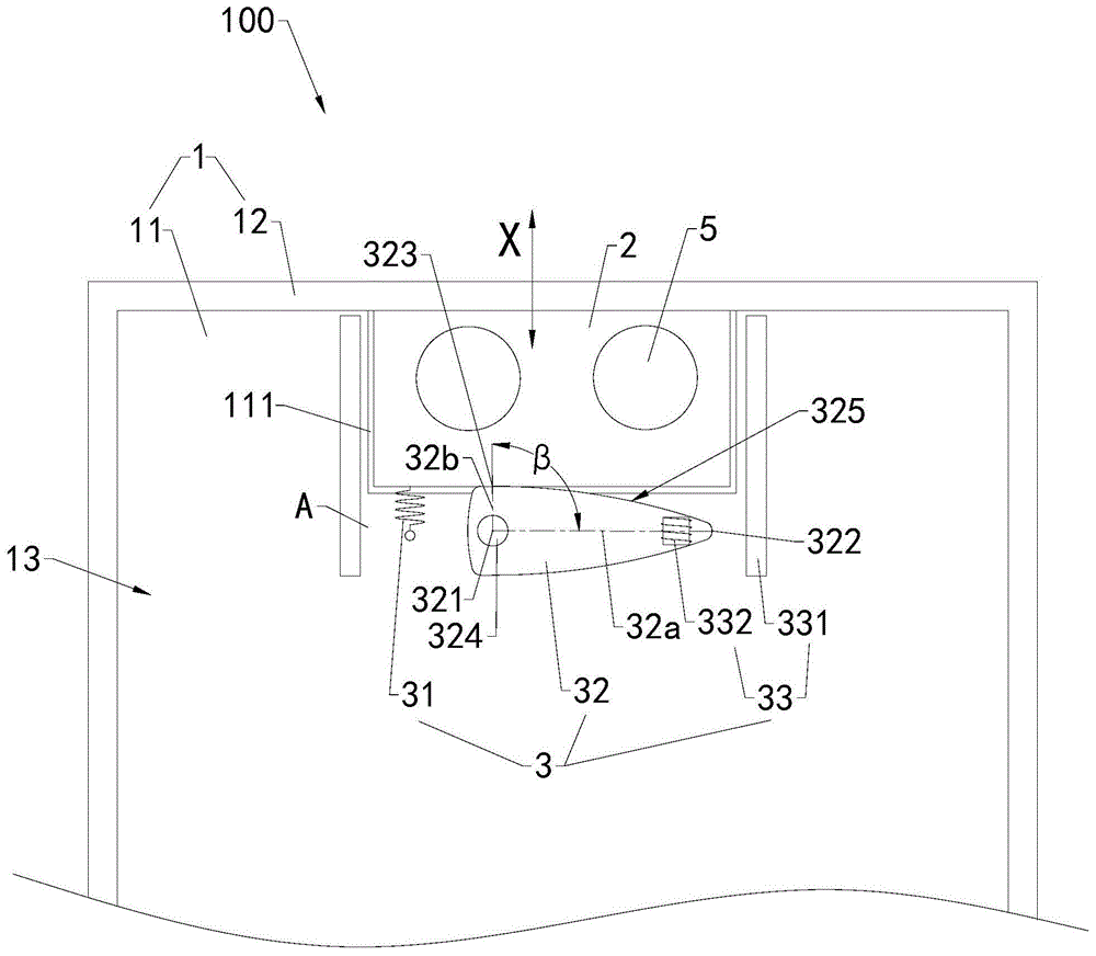
Referring to fig. 1 to fig. 3, a functional device 100 is provided in an embodiment of the present disclosure. The functional assembly 100 includes a base 1, a sliding seat 2 and a driving assembly 3. The sliding seat 2 is telescopically and slidably connected to the base 1. And the sliding seat 2 is provided with a camera module 4. The driving component 3 is arranged in the base 1. The driving assembly 3 includes an elastic member 31, a cam 32, and a driving member 33 for driving the cam 32 to rotate. One end of the elastic element 31 is fixed relative to the base 1, and the other end of the elastic element 31 is connected with the sliding seat 2. The cam 32 has a center of rotation 321, a distal point 322, and a proximal point 323. The distance between the distal end point 322 and the rotation center 321 is greater than the distance between the proximal end point 323 and the rotation center 321. When the driving member 33 drives the cam 32 to rotate, the contact position of the cam 32 and the sliding seat 2 moves from the proximal end point 323 to the distal end point 322 to push the sliding seat 2, so that the camera module 4 extends out of the base 1, and the elastic member 31 is stretched (as shown in fig. 3). When the driving member 33 is stopped, the elastic member 31 returns to draw close the sliding seat 2, so that the camera module 4 retracts into the base 1, and the cam 32 is pushed back to the original position (as shown in fig. 2). It is understood that, referring to fig. 1, the functional module 100 can be applied to an electronic device 200. The electronic device 200 may be a mobile phone, a tablet computer, a notebook computer, etc.
In this embodiment, when the driving element 33 drives the cam 32 to rotate, the contact position of the cam 32 and the sliding seat 2 moves from the proximal end point 323 to the distal end point 322, and the distance between the contact position of the cam 32 and the sliding seat 2 and the rotation center 321 increases to push the sliding seat 2, so that the camera module 4 extends out of the base 1, and the elastic element 31 is stretched. When the driving element 33 stops driving, the cam 32 is in an active state, the elastic element 31 returns to draw close the sliding seat 2, the contact position of the cam 32 and the sliding seat 2 moves from the distal end point 322 to the proximal end point 323, the distance between the contact position of the cam 32 and the sliding seat 2 and the rotation center 321 decreases, so that the camera module 4 retracts into the base 1, and the cam 32 is pushed back to the original position. When functional component 100 the camera module 4 stretches out during base 1, guaranteed camera module 4 and user interaction, when camera module 4 indentation during base 1, reduced the application the use volume of the electronic device 200 of functional component 100, the user of being convenient for carries electronic device 200, consequently functional component 100 has improved user experience.
It is understood that in other embodiments, the camera module 4 may be replaced by other functional devices, including but not limited to any one or more combinations of iris recognition module, face recognition module, flash, microphone, receiver, photoreceptor, fingerprint module, keys, etc. The first direction may be a counterclockwise direction or a clockwise direction. The rotating shaft 324 of the cam 32 is rotatably connected with the base 1. The rotation center 321 is located at the axis of the rotation shaft 324.
Optionally, the driving member 33 has various forms for driving the cam 32 to rotate, for example:
in one embodiment, referring to fig. 2 and 3, the driving member 33 includes a magnetic element 331 and a coil 332. The coil 332 is fixed to the cam 32. The magnetic member 331 is used to form a magnetic field covering the rotation range of the cam 32. When the coil 332 is energized, the cam 32 is rotated.
In this embodiment, since the driving member 33 drives the cam 32 to rotate by magnetic force, when the camera module 4 receives an impact force impacting towards the base 1, the sliding seat 2 can rapidly overcome the magnetic force of the driving member 33 and carry the camera module 4 to retract into the base 1, so as to prevent the camera module 4 from being damaged by rigid impact, and thus the functional assembly 100 and the electronic device 200 have high reliability. Meanwhile, the functional component 100 can also make the camera module 4 retract into the base 1 when the user manually presses the sliding seat 2, so as to meet the more diversified user requirements.
It can be understood that, when the driving member 33 stops driving, the coil 332 is de-energized, the cam 32 is in an active state, and the cam 32 removes the pushing force on the sliding seat 2, so that the elastic member 31 can rotate under the elastic force thereof and be pushed back to the original position by the sliding seat 2.
Wherein the magnetic member 331 includes a first magnet 3311 and a second magnet 3312. The first magnet 3311 and the second magnet 3312 are respectively located at both sides of the cam 32 in a direction perpendicular to the sliding direction of the sliding seat 2. The first magnet 3311 and the second magnet 3312 together form a magnetic field covering the rotational range of the cam 32.
Wherein the spacing between the coil 332 and the distal end point 322 is smaller than the spacing between the coil 332 and the center of rotation 321. At this time, the coil 332 is disposed closer to the distal end point 322 than the rotation center 321, and when the coil 332 is energized, the coil 332 can more easily drive the cam 32 to rotate, so as to reduce the energy consumption of the functional assembly 100. It will be appreciated that the closer the coil 332 is to the distal end point 322, the less magnetic force is required to drive the cam 32 to rotate and the lower the energy consumption of the functional assembly 100.
In another embodiment, referring to fig. 4 and 5, the driving member 33 includes a motor 333, a first gear 334 and a second gear 335. The first gear 334 is disposed coaxially with the cam 32. The second gear 335 is fixed to an output shaft of the motor 333. The second gear 335 meshes with the first gear 334. When the motor 333 is energized to rotate, the second gear 335 drives the cam 32 to rotate via the first gear 334. When the driving member 33 stops driving, the motor 333 is powered off, the output shaft of the motor 333 is in a movable state, the second gear 335 and the first gear 334 are also in a movable state, and the cam 32 is in a movable state, so that the cam can rotate under the elastic force of the elastic member 31 and be pushed back to the original position by the sliding seat 2.
The motor 333 can be a stepping motor or other servo motor capable of realizing precise control, so as to accurately control the rotation direction and rotation angle of the cam 32, thereby precisely controlling the sliding displacement of the sliding seat 2, and enabling the functional assembly 100 and the electronic device 200 to have better use experience and higher reliability.
Alternatively, one end of the elastic member 31 may be fixed to the rotation center 321. One end of the elastic member 31 is fixed to the rotation center 321, and the space in the base 1 can be reused, so as to reduce the overall volume of the functional assembly 100. In other embodiments, as shown in fig. 2, one end of the elastic member 31 may be fixed to the base 1 and disposed as close to the rotation center 321 as possible.
Optionally, referring to fig. 2 and 3, the outer surface of the cam 32 has a plurality of end points, and the end point farthest from the rotation center 321 is the distal end point 322. By disposing the distal point 322 at the farthest position from the rotation center 321, the volume of the cam 32 can be reduced, so as to reduce the space occupied by the functional component 100, which is beneficial to the light and thin electronic device 200.
It is understood that in other embodiments, as shown in fig. 6, the distal end point 322 may not be the end point farthest from the plurality of end points, and only needs to be as far away from the rotation center 321 as possible.
In one embodiment, the end point closest to the rotation center 321 among the plurality of end points may be set as the near end point 323.
Optionally, referring to fig. 6, a connection line between the distal end point 322 and the rotation center 321 is a first connection line 32 a. A tangent 32c to the cam 32 at the distal point 322 forms an angle a with the first line 32a, which angle a is not equal to 90 °. At this time, when the sliding seat 2 is pushed by the cam 32 under the action of an external force, the cam 32 can be prevented from being stuck, so that the risk of damage to the functional assembly 100 is reduced.
Optionally, referring to fig. 2 and fig. 3, a connection line between the distal end point 322 and the rotation center 321 is a first connection line 32a, and a connection line between the proximal end point 323 and the rotation center 321 is a second connection line 32 b. An angle β between the second line 32b and the first line 32a is equal to or greater than 60 ° and equal to or less than 120 °. For example, the second wire 32b is perpendicular to the first wire 32 a. In the present embodiment, the rotation range of the cam 32 is smaller, so that the space occupied by the functional assembly 100 can be reduced, which is beneficial to the light and thin electronic device 200.
Optionally, referring to fig. 2, the outer surface of the cam 32 includes a holding section 325, the holding section 325 is located between the distal end point 322 and the proximal end point 323, and the holding section 325 is a smooth curved surface. At this time, the cam 32 can stably push the sliding seat 2, and in the process of relative movement between the cam 32 and the sliding seat 2, the risk of abrasion between the cam 32 and the sliding seat 2 is reduced.
Optionally, referring to fig. 2, fig. 3 and fig. 7, the base 1 includes a bottom plate 11 and a frame 12 connected to a periphery of the bottom plate 11. The bottom plate 11 and the frame 12 enclose the accommodating cavity 13. The driving assembly 3 is accommodated in the accommodating cavity 13. The frame 12 is provided with a telescopic opening 121 communicated to the accommodating cavity 13, and the sliding seat 2 is slidably connected to the frame 12 through the telescopic opening 121, so that the camera module 4 extends out of or retracts into the accommodating cavity 13 through the telescopic opening 121. The bottom plate 11 may be a rear cover or a middle partition plate of the electronic device 200. The frame 12 may be a peripheral frame of the electronic device 200.
In this embodiment, the bottom plate 11 of the base 1 supports the sliding seat 2 and the driving component 3, so as to ensure that the driving component 3 can drive the sliding seat 2 to extend and retract relative to the base 1. The frame 12 covers and hides the sliding seat 2 and the driving component 3, so as to improve the appearance performance and the safety performance of the functional component 100. Because the expansion port 121 is disposed on the frame 12, the camera module 4 extends and contracts at the side of the base 1, that is, the camera module 4 extends and contracts at the side of the electronic device 200, and the camera module 4 does not occupy the front space of the electronic device 200, so as to avoid the limitation on the screen occupation ratio of the electronic device 200.
Wherein, the outer peripheral side wall of the sliding seat 2 is in clearance fit with the inner peripheral side wall of the expansion port 121. At this time, the clearance between the outer peripheral side wall of the sliding seat 2 and the inner peripheral side wall of the expansion port 121 can ensure that the sliding seat 2 can slide smoothly relative to the base 1.
Optionally, the bottom plate 11 is provided with a guide groove 111, the guide groove 111 communicates the accommodating cavity 13 and the expansion port 121, and the sliding seat 2 slides along the guide groove 111. The guide groove 111 is used for cooperating with the telescopic opening 121 to define the sliding direction of the sliding seat 2 together, so as to ensure that the camera module 4 smoothly extends out of the accommodating cavity 13 or retracts into the accommodating cavity 13.
A space is formed between an end surface of the guide groove 111 away from the frame 12 and an outer side surface of the frame 12 (i.e., a side surface away from the accommodating cavity 13). The slide holder 2 has a length dimension in the extending direction of the guide groove 111. The ratio of the pitch to the length dimension is 1 or more and 1.1 or less. At this time, the end surface of the guide groove 111 far from the frame 12 can limit the sliding seat 2, limit the depth of the sliding seat 2 extending into the accommodating cavity 13, and prevent the sliding seat 2 from completely falling into the accommodating cavity 13, thereby ensuring the reliability of the functional assembly 100 and the electronic device 200. Moreover, when the functional component 100 is accidentally impacted and the camera module 4 retracts into the accommodating cavity 13, the sliding seat 2 can be protected in a limiting manner.
Optionally, referring to fig. 2, fig. 3, fig. 7 and fig. 8, the sliding seat 2 includes a base 21 and a baffle 22 fixed on one side of the base 21. The base 21 encloses a device space 211. The camera module 4 is accommodated in the device space 211. The baffle 22 is perpendicular to the sliding direction of the sliding seat 2. When the camera module 4 retracts into the accommodating cavity 13, the baffle 22 covers the expansion port 121. The baffle 22 is used to prevent outside moisture and dust from entering the accommodating cavity 13 through the expansion port 121, so as to improve the reliability of the camera module 4 and the electronic device 200.
The outer peripheral side wall of the sliding seat 2 is in clearance fit with the inner peripheral side wall of the expansion port 121, so that the sliding seat 2 can smoothly slide relative to the frame 12.
Optionally, as shown in fig. 8, the sliding seat 2 further includes a cover plate 23. The cover plate 23 is connected to the base 21 to cover the device space 211. The cover plate 23 is provided with a light-transmitting portion 231 facing the camera module 4. The light-transmitting portion 231 may be a light-transmitting lens or a light-transmitting hole.
In the present embodiment, the cover 23 and the base 21 together surround the camera module 4, thereby playing a role of protection. The light-transmitting portion 231 provided on the cover plate 23 enables the camera module 4 to smoothly interact with a user when extending out of the accommodating cavity 13.
Optionally, at least one of an iris recognition module, a face recognition module, a fingerprint recognition module, a flash, a photosensor, a receiver, and a microphone is further accommodated in the device space 211. The cover plate 23 is further provided with a signal penetration portion for allowing a signal to pass through the cover plate 23 to interact with a device in the sliding seat 2. The signal penetration portion may be a light-transmitting lens, a perforated plate, or a through hole to allow an acoustic signal or a light signal to pass therethrough. As shown in fig. 8, the device space 211 also accommodates therein the flash 5 and the circuit board 6. The flash lamp 5 is fixed on the circuit board 6 and electrically connected with the circuit board 6. The camera module 4 is electrically connected to the circuit board 6 through an electrical connector.
Optionally, the functional assembly 100 further includes a Flexible Printed Circuit (FPC). One end of the flexible circuit board extends into the sliding seat 2 and is electrically connected with the camera module 4, and the other end of the flexible circuit board extends out of the sliding seat 2. The other end of the flexible circuit board is located in the receiving cavity 13 to electrically connect other devices located in the receiving cavity 13, such as a motherboard of the electronic device 200.
Referring to fig. 1 to 8, an electronic device 200 is also provided in the present embodiment. The electronic device 200 comprises the functional assembly 100 according to any of the above embodiments. The electronic device 200 according to the embodiment of the present application may be any device having communication and storage functions, for example: the system comprises intelligent equipment with a network function, such as a tablet Computer, a mobile phone, an electronic reader, a remote controller, a Personal Computer (PC), a notebook Computer, vehicle-mounted equipment, a network television, wearable equipment and the like. The electronic device 200 further includes a battery, a main board, and the like accommodated in the accommodating cavity 13.
Optionally, the accommodating cavity 13 has an accommodating opening perpendicular to the sliding direction of the camera module 4. The electronic device 200 further comprises a display screen 300, and the display screen 300 is fixed on the base 1. Specifically, the display screen 300 covers the base 1 and covers the receiving opening. Because the camera module 4 can flexibly extend out of the accommodating cavity 13 or retract into the accommodating cavity 13 according to the use requirement, the camera module 4 does not occupy the front space of the electronic device 200, and the screen occupation ratio of the display screen 300 is not limited, so that the screen occupation ratio of the electronic device 200 can be improved, and the full-screen display development requirement of the electronic device 200 is facilitated.
Wherein, camera module 4 indentation when base 1, the display area of display screen 300 at least part covers camera module 4. As shown in fig. 1, the exposed portion of the display screen 300 is entirely the display area of the display screen 300 or almost entirely the display area of the display screen 300. Because the camera module 4 does not need to occupy the position of the display area, the display area can have an area as large as possible, so that the screen occupation ratio of the display screen 300 is increased, and the overall screen display requirement of the electronic device 200 is met. Camera module 4 does not occupy the position on display screen 300 among electronic device 200, reduces the processing such as hollowing or punching to display screen 300, reduces the manufacturing procedure to display screen 300, camera module 4 does not also occupy the position on the display area among electronic device 200 to improve electronic device 200's screen and account for than, convenient operation improves user experience.
The display screen 300 may be a touch display screen. The Display screen 300 may be a Liquid Crystal Display (LCD) or an Organic Light-Emitting Display (OLED).
Referring to fig. 1 to 9, an embodiment of the present application further provides a method for controlling an electronic device. The control method of the electronic device is applied to the electronic device 200 according to any of the foregoing embodiments. The electronic device 200 comprises a base 1, a sliding seat 2 and a driving assembly 3, wherein the sliding seat 2 is telescopically and slidably connected to the base 1, a camera module 4 is arranged on the sliding seat 2, the driving assembly 3 is arranged in the base 1, the driving assembly 3 comprises an elastic piece 31, a cam 32 and a driving piece 33 used for driving the cam 32 to rotate, one end of the elastic piece 31 is fixed relative to the base 1, the other end of the elastic piece 31 is connected to the sliding seat 2, the cam 32 is provided with a rotation center 321, a far end point 322 and a near end point 323, and the distance between the far end point 322 and the rotation center 321 is greater than the distance between the near end point 323 and the rotation center 321.
The control method of the electronic device comprises the following steps:
101: the electronic device 200 receives an extension signal, the electronic device 200 controls the driving member 33 to drive the cam 32 to rotate according to the extension signal, the contact position of the cam 32 and the sliding seat 2 moves from the proximal point 323 to the distal point 322 to push the sliding seat 2, so that the camera module 4 extends out of the base 1, and the elastic member 31 is stretched;
102: the electronic device 200 receives the contraction signal, the electronic device 200 stops driving the driving member 33 according to the contraction signal, the elastic member 31 is restored to draw close the sliding seat 2, so that the camera module 4 retracts into the base 1, and the cam 32 is pushed back to the original position.
It is understood that the electronic device 200 further includes a controller (not shown). The electronic device 200 can receive the extension signal or the contraction signal through a touch display screen 300, a receiver, a photosensitive element, a flash lamp, and the like, and control the driving component 3 through a controller.
In this embodiment, when a user needs to take a picture, the electronic device 200 inputs the extension signal to extend the camera module 4 out of the base 1 for taking a picture. At this time, the extension signal is a photographing signal. When the user finishes shooting, the camera module 4 can be retracted into the base 1 by inputting the retraction signal to the electronic device 200. At this time, the contraction signal is a shooting completion signal.
Optionally, the control method of the electronic device further includes:
when the extension length of the sliding seat 2 reaches a first threshold and the acceleration of the electronic device 200 reaches a second threshold, the electronic device 200 stops driving the driving element 33, the elastic element 31 returns to draw close the sliding seat 2, so that the camera module 4 retracts into the base 1, and the cam 32 is pushed back to the original position.
Wherein the electronic device 200 further comprises a gravity sensor for detecting an acceleration of the electronic device 200. The electronic device 200 may detect the protruding length of the sliding seat 2 through a pressure sensor, an infrared distance meter, a trigger switch, or the like. When the acceleration reaches a second threshold, the electronic device 200 is in a drop environment. The controller is further configured to determine a relationship between the extension length of the sliding seat 2 and the first threshold. The gravity sensor is electrically connected to the controller, and the controller is further configured to determine a relationship between the acceleration of the electronic device 200 and the second threshold. The controller controls the driving assembly 3 and the pulling assembly to enable the sliding seat 2 to carry the camera module 4 to retract into the base 1, so that the camera module 4 is prevented from falling and being damaged.
The foregoing is an embodiment of the present application, and it should be noted that, for those skilled in the art, several modifications and decorations can be made without departing from the principle of the embodiment of the present application, and these modifications and decorations are also regarded as the protection scope of the present application.