CN110096112B - Hard disk device, hard disk adapter device, network device and hard disk connection method - Google Patents
Hard disk device, hard disk adapter device, network device and hard disk connection method Download PDFInfo
- Publication number
- CN110096112B CN110096112B CN201910358524.0A CN201910358524A CN110096112B CN 110096112 B CN110096112 B CN 110096112B CN 201910358524 A CN201910358524 A CN 201910358524A CN 110096112 B CN110096112 B CN 110096112B
- Authority
- CN
- China
- Prior art keywords
- hard disk
- location area
- pins
- connector
- sas
- Prior art date
- Legal status (The legal status is an assumption and is not a legal conclusion. Google has not performed a legal analysis and makes no representation as to the accuracy of the status listed.)
- Active
Links
Images


Classifications
-
- G—PHYSICS
- G06—COMPUTING OR CALCULATING; COUNTING
- G06F—ELECTRIC DIGITAL DATA PROCESSING
- G06F1/00—Details not covered by groups G06F3/00 - G06F13/00 and G06F21/00
- G06F1/16—Constructional details or arrangements
- G06F1/18—Packaging or power distribution
- G06F1/183—Internal mounting support structures, e.g. for supporting printed circuit boards
- G06F1/187—Mounting of fixed or removable disk drives
Landscapes
- Engineering & Computer Science (AREA)
- Theoretical Computer Science (AREA)
- Computer Hardware Design (AREA)
- Power Engineering (AREA)
- Human Computer Interaction (AREA)
- Physics & Mathematics (AREA)
- General Engineering & Computer Science (AREA)
- General Physics & Mathematics (AREA)
- Mounting Of Printed Circuit Boards And The Like (AREA)
- Debugging And Monitoring (AREA)
Abstract
本申请提供了一种硬盘装置、硬盘转接装置、网络设备与硬盘的连接方法。其中,该硬盘装置包括硬盘背板连接器和硬盘连接器;硬盘背板连接器包括第一SAS通道对应的第一引脚组和第二SAS通道对应的第二引脚组;硬盘连接器为标准硬盘连接器;硬盘连接器包括预设的第一位置区、第二位置区和第三位置区,第三位置区存在至少一个引脚不属于第二位置区;第一引脚组与第一位置区的引脚连接,第二引脚组与第三位置区的引脚连接;第二位置区中除去属于第三位置区的引脚之外的引脚,与硬盘背板连接器为断开状态。在该引脚连接方式下,硬盘装置支持在同硬盘槽位兼容不同类型硬盘的基础上,提高性能。
The present application provides a hard disk device, a hard disk adapter device, and a connection method between a network device and a hard disk. The hard disk device includes a hard disk backplane connector and a hard disk connector; the hard disk backplane connector includes a first pin group corresponding to the first SAS channel and a second pin group corresponding to the second SAS channel; the hard disk connector is Standard hard disk connector; the hard disk connector includes a preset first location area, a second location area and a third location area, and there is at least one pin in the third location area that does not belong to the second location area; The pins of a location area are connected, and the second pin group is connected to the pins of the third location area; the pins in the second location area except the pins belonging to the third location area are connected to the hard disk backplane connector as disconnected state. In this pin connection method, the hard disk device supports the compatibility of different types of hard disks with the hard disk slot, and improves the performance.
Description
技术领域technical field
本公开涉及计算机技术领域,尤其是涉及一种硬盘装置、硬盘转接装置、网络设备与硬盘的连接方法。The present disclosure relates to the field of computer technology, and in particular, to a hard disk device, a hard disk adapter device, and a method for connecting a network device and a hard disk.
背景技术Background technique
计算机服务器的硬盘由传统的机械硬盘发展为固态硬盘,硬盘的接口目前主要包括:ATA(Advanced Technology Attachment,高技术配置)接口、SAS接口(Serial AttachedSmall Computer System Interface,串行连接小型计算机系统接口)、NVMe SSD接口(Non-Volatile Memory express SSD,非易失性内存主机控制器接口)等。The hard disk of a computer server has been developed from a traditional mechanical hard disk to a solid-state hard disk. The hard disk interfaces currently mainly include: ATA (Advanced Technology Attachment, high-tech configuration) interface, SAS interface (Serial AttachedSmall Computer System Interface, serial connection Small computer system interface) , NVMe SSD interface (Non-Volatile Memory express SSD, non-volatile memory host controller interface), etc.
刀片计算节点服务器出面板的硬盘槽位,可以支持安装1个HDD(HDD,Hard DiskDrive)或1个SSD(包括SAS SSD/SATA SSD/NVMeSSD)硬盘,为了扩充存储容量,可以通过硬盘连接器连接2个SATA M.2固态硬盘。SATA M.2固态硬盘具有结构体积小,性能好,使用很广泛的特点。而该硬盘连接器通常为标准的硬盘连接器,其各个引脚的功能比较固定,限制了同一硬盘槽位在兼容不同类型硬盘时的使用性能。The hard disk slot on the panel of the blade computing node server can support the installation of 1 HDD (HDD, Hard DiskDrive) or 1 SSD (including SAS SSD/SATA SSD/NVMeSSD). 2 SATA M.2 SSDs. SATA M.2 solid state drives have the characteristics of small size, good performance and wide use. The hard disk connector is usually a standard hard disk connector, and the functions of each pin are relatively fixed, which limits the performance of the same hard disk slot when it is compatible with different types of hard disks.
发明内容SUMMARY OF THE INVENTION
有鉴于此,本公开的目的在于提供一种硬盘装置、硬盘转接装置、网络设备与硬盘的连接方法,以在同一硬盘槽位在兼容不同类型硬盘的基础上,提升其使用性能。In view of this, the purpose of the present disclosure is to provide a method for connecting a hard disk device, a hard disk adapter device, a network device and a hard disk, so as to improve the use performance of the same hard disk slot on the basis of being compatible with different types of hard disks.
为了实现上述目的,本公开采用的技术方案如下:In order to achieve the above object, the technical solution adopted in the present disclosure is as follows:
第一方面,本公开实施方式提供了一种硬盘装置,包括:硬盘背板连接器和硬盘连接器;硬盘背板连接器包括第一SAS通道对应的第一引脚组和第二SAS通道对应的第二引脚组;硬盘连接器为标准硬盘连接器;其中,硬盘连接器包括预设的第一位置区、第二位置区和第三位置区,第三位置区存在至少一个引脚不属于第二位置区;第一引脚组中的引脚与第一位置区中的引脚对应连接,第二引脚组中的引脚与第三位置区中的引脚对应连接;第二位置区中除去属于第三位置区的引脚之外的引脚,与硬盘背板连接器间为断开状态。In a first aspect, embodiments of the present disclosure provide a hard disk device, including: a hard disk backplane connector and a hard disk connector; the hard disk backplane connector includes a first pin group corresponding to a first SAS channel and a second SAS channel corresponding to The second pin group; the hard disk connector is a standard hard disk connector; wherein, the hard disk connector includes a preset first location area, a second location area and a third location area, and there is at least one pin in the third location area. It belongs to the second location area; the pins in the first pin group are correspondingly connected with the pins in the first location area, and the pins in the second pin group are correspondingly connected with the pins in the third location area; the second The pins in the location area except the pins belonging to the third location area are disconnected from the hard disk backplane connector.
第二方面,本公开实施方式提供了一种硬盘转接装置,包括:第一硬盘连接器和第二硬盘连接器和第三硬盘连接器;第一硬盘连接器为标准硬盘连接器;第一硬盘连接器包括预设的第一位置区、第二位置区和第三位置区,第三位置区存在至少一个引脚不属于第二位置区;第二硬盘连接器和第三硬盘连接器分别用于连接两个独立的SATA M.2硬盘;第二硬盘连接器中的引脚与第一位置区中的引脚对应连接,第三硬盘连接器中的引脚与第三位置区中的引脚对应连接;第二位置区中除去属于第三位置区的引脚之外的引脚,与第二硬盘连接器和第三硬盘连接器均为断开状态。In a second aspect, embodiments of the present disclosure provide a hard disk adapter device, including: a first hard disk connector, a second hard disk connector, and a third hard disk connector; the first hard disk connector is a standard hard disk connector; the first hard disk connector The hard disk connector includes a preset first position area, a second position area and a third position area, and there is at least one pin in the third position area that does not belong to the second position area; the second hard disk connector and the third hard disk connector are respectively Used to connect two independent SATA M.2 hard disks; the pins in the second hard disk connector are correspondingly connected with the pins in the first position area, and the pins in the third hard disk connector are connected with the pins in the third position area. The pins are connected correspondingly; the pins in the second location area except the pins belonging to the third location area are disconnected from the second hard disk connector and the third hard disk connector.
第三方面,本公开实施方式提供了一种网络设备,包括母板和硬盘背板;其中,该母板包括母板主体、设置在母板主体上的控制器和第一硬盘背板连接器;控制器与第一硬盘背板连接器连接形成第一SAS通道和第二SAS通道;硬盘背板包括:背板主体、以及设置在背板主体上的第二硬盘背板连接器和硬盘连接器;第一硬盘背板连接器和第二硬盘背板连接器相互适配;第二硬盘背板连接器包括第一SAS通道对应的第一引脚组和第二SAS通道对应的第二引脚组;硬盘连接器为标准硬盘连接器;其中,硬盘连接器包括预设的第一位置区、第二位置区和第三位置区,第三位置区存在至少一个引脚不属于第二位置区;第一引脚组中的引脚与第一位置区中的引脚对应连接,第二引脚组中的引脚与第三位置区中的引脚对应连接;第二位置区中除去属于第三位置区的引脚之外的引脚,与第二硬盘背板连接器间为断开状态。In a third aspect, embodiments of the present disclosure provide a network device including a motherboard and a hard disk backplane; wherein the motherboard includes a motherboard body, a controller disposed on the motherboard body, and a first hard disk backplane connector The controller is connected with the first hard disk backplane connector to form a first SAS channel and a second SAS channel; the hard disk backplane includes: a backplane main body, and a second hard disk backplane connector and a hard disk connected The first hard disk backplane connector and the second hard disk backplane connector are adapted to each other; the second hard disk backplane connector includes a first pin group corresponding to the first SAS channel and a second pin group corresponding to the second SAS channel Pin group; the hard disk connector is a standard hard disk connector; wherein, the hard disk connector includes a preset first position area, a second position area and a third position area, and there is at least one pin in the third position area that does not belong to the second position area; the pins in the first pin group are correspondingly connected with the pins in the first position area, and the pins in the second pin group are correspondingly connected with the pins in the third position area; The pins other than the pins belonging to the third position area are disconnected from the second hard disk backplane connector.
第四方面,本公开实施方式提供了一种网络设备与硬盘的连接方法,该方法应用于第三方面所述的网络设备,包括:如果控制器监听到有硬盘连接至硬盘背板,获取硬盘的类型;其中,硬盘的类型包括SAS硬盘或SATA M.2双硬盘;如果硬盘的类型为SAS硬盘,通过第一SAS通道与硬盘建立连接;如果硬盘的类型为SATA M.2双硬盘,通过第一SAS通道和第二SAS通道与SATA M.2双硬盘的每个硬盘分别建立连接。In a fourth aspect, an embodiment of the present disclosure provides a method for connecting a network device and a hard disk. The method is applied to the network device described in the third aspect, including: if the controller detects that a hard disk is connected to the hard disk backplane, obtaining the hard disk Among them, the type of hard disk includes SAS hard disk or SATA M.2 dual hard disk; if the hard disk type is SAS hard disk, establish a connection with the hard disk through the first SAS channel; if the hard disk type is SATA M.2 dual hard disk, through The first SAS channel and the second SAS channel are respectively connected to each hard disk of the SATA M.2 dual hard disk.
上述公开实施方式提供了一种硬盘装置、硬盘转接装置、网络设备与硬盘的连接方法,其中,硬盘装置的硬盘背板连接器包括第一SAS通道对应的第一引脚组和第二SAS通道对应的第二引脚组;硬盘装置的硬盘连接器为标准硬盘连接器;该硬盘连接器包括预设的第一位置区、第二位置区和第三位置区,第三位置区存在至少一个引脚不属于第二位置区;第一引脚组中的引脚与第一位置区中的引脚对应连接,第二引脚组中的引脚与第三位置区中的引脚对应连接;第二位置区中除去属于第三位置区的引脚之外的引脚,与硬盘背板连接器间为断开状态。这种通过设定第一位置区与第一引脚组连接,且第二位置区中除去属于第三位置区的引脚之外的引脚,与硬盘背板连接器间为断开状态的方式,使得硬盘连接器的第一位置区和第二位置区中至少有一个引脚与硬盘背板连接器处于断开状态,当硬盘装置安插上SAS硬盘时,SAS硬盘仅在第一位置区对应的SAS通道上握手连接成功,与第二位置区对应的SAS通道由于至少有一个引脚与硬盘背板连接器处于断开状态,将握手连接失败,进而使SAS硬盘在与硬盘装置建立连接通道时,不会在两个SAS通道间跳变,因此能够使显示的SAS硬盘在线的槽位号与实际槽位号一致,保障了后续软件业务配置的有效性。同时,因为该硬盘背板连接器为标准的硬盘背板连接器,在上述引脚连接方式下,该硬盘背板连接器依然支持2个SATA M.2硬盘的使用,在同一硬盘槽位在兼容不同类型硬盘的基础上,提升了其使用性能。The above disclosed embodiments provide a method for connecting a hard disk device, a hard disk adapter device, a network device and a hard disk, wherein the hard disk backplane connector of the hard disk device includes a first pin group corresponding to a first SAS channel and a second SAS The second pin group corresponding to the channel; the hard disk connector of the hard disk device is a standard hard disk connector; the hard disk connector includes a preset first position area, a second position area and a third position area, and the third position area has at least A pin does not belong to the second location area; the pins in the first pin group correspond to the pins in the first location area, and the pins in the second pin group correspond to the pins in the third location area Connection; pins in the second location area except the pins belonging to the third location area are disconnected from the hard disk backplane connector. By setting the first location area to connect with the first pin group, and the pins in the second location area except the pins belonging to the third location area are disconnected from the hard disk backplane connector The method is such that at least one pin in the first position area and the second position area of the hard disk connector is disconnected from the hard disk backplane connector. When the hard disk device is installed with a SAS hard disk, the SAS hard disk is only in the first position area. The handshake connection is successful on the corresponding SAS channel. Since at least one pin of the SAS channel corresponding to the second location area is disconnected from the hard disk backplane connector, the handshake connection fails, and the SAS hard disk is connected to the hard disk device. When the channel is selected, it will not switch between two SAS channels, so the displayed slot number of the SAS hard disk online can be consistent with the actual slot number, which ensures the effectiveness of subsequent software service configuration. At the same time, because the hard disk backplane connector is a standard hard disk backplane connector, the hard disk backplane connector still supports the use of 2 SATA M.2 hard disks under the above pin connection method. On the basis of being compatible with different types of hard drives, its performance has been improved.
本公开的其他特征和优点将在随后的说明书中阐述,或者,部分特征和优点可以从说明书推知或毫无疑义地确定,或者通过实施本公开的上述技术即可得知。Additional features and advantages of the present disclosure will be set forth in the description that follows, or some may be inferred or unambiguously determined from the description, or may be learned by practicing the above-described techniques of the present disclosure.
为使本公开的上述目的、特征和优点能更明显易懂,下文特举较佳实施方式,并配合所附附图,作详细说明如下。In order to make the above-mentioned objects, features and advantages of the present disclosure more obvious and easy to understand, the preferred embodiments are exemplified below, and are described in detail as follows in conjunction with the accompanying drawings.
附图说明Description of drawings
为了更清楚地说明本公开具体实施方式或现有技术中的技术方案,下面将对具体实施方式或现有技术描述中所需要使用的附图作简单地介绍,显而易见地,下面描述中的附图是本公开的一些实施方式,对于本领域普通技术人员来讲,在不付出创造性劳动的前提下,还可以根据这些附图获得其他的附图。In order to illustrate the specific embodiments of the present disclosure or the technical solutions in the prior art more clearly, the following briefly introduces the accompanying drawings that need to be used in the description of the specific embodiments or the prior art. Obviously, the accompanying drawings in the following description The drawings are some embodiments of the present disclosure. For those of ordinary skill in the art, other drawings can also be obtained based on these drawings without creative efforts.
图1为本公开实施方式提供的一种固态硬盘面板示意图;FIG. 1 is a schematic diagram of a solid-state drive panel according to an embodiment of the present disclosure;
图2为本公开实施方式提供的一种M.2硬盘与硬盘背板的连接示意图;FIG. 2 is a schematic diagram of a connection between an M.2 hard disk and a hard disk backplane according to an embodiment of the present disclosure;
图3为本公开实施方式提供的一种以SFF-8639规则定义的硬盘连接器的引脚示意图;3 is a schematic diagram of pins of a hard disk connector defined by SFF-8639 rules provided by an embodiment of the present disclosure;
图4为本公开实施方式提供的一种SAS硬盘与硬盘背板的连接示意图;4 is a schematic diagram of a connection between a SAS hard disk and a hard disk backplane according to an embodiment of the present disclosure;
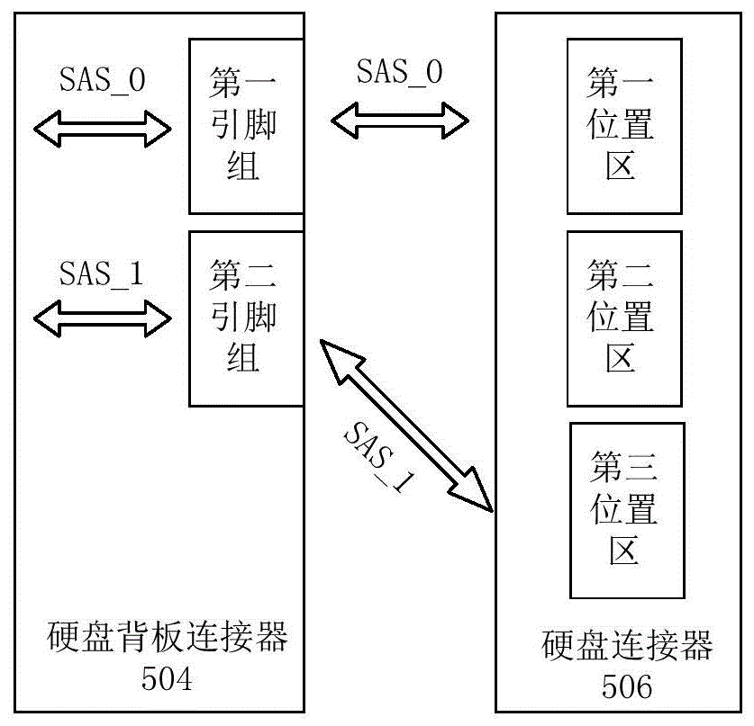
图5为本公开实施方式提供的一种硬盘装置的结构示意图;5 is a schematic structural diagram of a hard disk device according to an embodiment of the present disclosure;
图6为本公开实施方式提供的一种硬盘转接装置的结构示意图;6 is a schematic structural diagram of a hard disk adapter device according to an embodiment of the present disclosure;
图7为本公开实施方式提供的一种网络设备的结构示意图;FIG. 7 is a schematic structural diagram of a network device according to an embodiment of the present disclosure;
图8为本公开实施方式提供的一种M.2硬盘的链路拓扑图;FIG. 8 is a link topology diagram of an M.2 hard disk provided by an embodiment of the present disclosure;
图9为本公开实施方式提供的一种SAS硬盘的链路拓扑图;FIG. 9 is a link topology diagram of a SAS hard disk provided by an embodiment of the present disclosure;
图10为本公开实施方式提供的一种网络设备与硬盘的连接方法的流程图。FIG. 10 is a flowchart of a method for connecting a network device and a hard disk according to an embodiment of the present disclosure.
具体实施方式Detailed ways
为使本公开实施方式的目的、技术方案和优点更加清楚,下面将结合附图对本公开的技术方案进行清楚、完整地描述,显然,所描述的实施方式是本公开一部分实施方式,而不是全部的实施方式。基于本公开中的实施方式,本领域普通技术人员在没有做出创造性劳动前提下所获得的所有其他实施方式,都属于本公开保护的范围。In order to make the purposes, technical solutions and advantages of the embodiments of the present disclosure more clear, the technical solutions of the present disclosure will be clearly and completely described below with reference to the accompanying drawings. Obviously, the described embodiments are part of the embodiments of the present disclosure, but not all of them. implementation. Based on the embodiments in the present disclosure, all other embodiments obtained by those of ordinary skill in the art without creative efforts shall fall within the protection scope of the present disclosure.
图1所示的固态硬盘面板示意图,该面板包括三个槽位,其中,槽位102用于支持HHD(Hard Disk Drive,机械硬盘)或SSD(SSD,Solid State Drive,固态硬盘);槽位104用于支持HDD或SSD,该固态硬盘包括SAS(Serial Attached Small Computer SystemInterface,串行连接小型计算机系统接口)、SSD/SATA(Serial Advanced TechnologyAttachment,串行高技术配置)、SSD/NVMe SSD(Non-Volatile Memory express SSD,非易失性内存主机控制器接口)等接口的硬盘;槽位106包括第一子槽位108和第二子槽位110,该槽位106用于支持SAS/SATA接口的硬盘(后文简称SAS硬盘)。同时由于SATA M.2接口的固态硬盘(后文简称M.2硬盘)具有较小的结构体积,槽位106还可以通过第一子槽位108和第二子槽位110扩展为支持2个M.2硬盘。上述硬盘均可以通过槽口配置的标准硬盘连接器,与服务器的主板RAID卡通信。基于此,上述硬盘背板即可实现更大容量硬盘扩展的目的。The schematic diagram of the solid state drive panel shown in FIG. 1, the panel includes three slots, wherein the slot 102 is used to support HHD (Hard Disk Drive, mechanical hard disk) or SSD (SSD, Solid State Drive, solid state drive); 104 is used to support HDD or SSD. The solid state drive includes SAS (Serial Attached Small Computer System Interface), SSD/SATA (Serial Advanced Technology Attachment, serial high-tech configuration), SSD/NVMe SSD (Non -Volatile Memory express SSD, non-volatile memory host controller interface) and other interfaces; the slot 106 includes a first sub-slot 108 and a second sub-slot 110, the slot 106 is used to support the SAS/SATA interface hard disk (hereinafter referred to as SAS hard disk). At the same time, since the solid-state hard disk of the SATA M.2 interface (hereinafter referred to as the M.2 hard disk) has a small structural volume, the slot 106 can also be expanded to support two through the first sub-slot 108 and the second sub-slot 110. M.2 hard drive. All of the above hard disks can communicate with the server's motherboard RAID card through standard hard disk connectors configured in the slots. Based on this, the above-mentioned hard disk backplane can achieve the purpose of expanding a larger capacity hard disk.
为了实现上述槽位106兼容SAS硬盘和2个SATA M.2硬盘(如上述M.2硬盘)的目的,两个固态硬盘可以通过硬盘转接板(如M.2转接板)安装在标准硬盘连接器上,以M.2硬盘为例,如图2所示的一种M.2硬盘与硬盘背板的连接示意图。其中,硬盘背板的一侧设置有硬盘背板连接器-母,用于与母板上的硬盘背板连接器-公对接,以实现母板与硬盘背板上形成两个SAS通道,即图中的SAS_0和SAS_1。硬盘背板的另一侧设置有硬盘连接器-母,该硬盘连接器-母为标准的硬盘连接器,与图1所示的槽位106类似,其上有两个子槽位,该两个子槽位可以通过M.2转接板与M.2硬盘连接;该M.2转接板的一个侧面设置有硬盘连接器-公,用于与硬盘背板上的硬盘连接器-母对接;M.2转接板的另一个侧面设置有两个M.2连接器-母,两个M.2连接器-母用于与硬盘连接器-公通信连接,以与硬盘连接器-公构建M.2转接板的两个通道;M.2硬盘可以通过与M.2连接器-母对接,以与M.2转接板上的两个通道通信连接。In order to achieve the purpose that the above-mentioned slot 106 is compatible with SAS hard disks and 2 SATA M.2 hard disks (such as the above M.2 hard disks), the two SSDs can be installed in the standard On the hard disk connector, take the M.2 hard disk as an example, as shown in Figure 2, a schematic diagram of the connection between the M.2 hard disk and the hard disk backplane. One side of the hard disk backplane is provided with a hard disk backplane connector-female, which is used for docking with the hard disk backplane connector-male on the motherboard, so as to form two SAS channels between the motherboard and the hard disk backplane, namely SAS_0 and SAS_1 in the figure. The other side of the hard disk backplane is provided with a hard disk connector-female, the hard disk connector-female is a standard hard disk connector, similar to the slot 106 shown in FIG. The slot can be connected to the M.2 hard disk through the M.2 adapter board; one side of the M.2 adapter board is provided with a hard disk connector-male, which is used for docking with the hard disk connector-female on the hard disk backplane; The other side of the M.2 adapter board is provided with two M.2 connectors-female, and two M.2 connectors-female are used to connect with the hard disk connector-male communication to build with the hard disk connector-male Two channels of the M.2 adapter board; M.2 hard drives can be connected to the two channels on the M.2 adapter board by docking with the M.2 connector-female.
上述硬盘连接器-母的各个引脚的功能定义可以按照SFF-8639规则定义,为了便于清楚说明,图3示出了一种以SFF-8639规则定义的硬盘连接器的引脚示意图。The function definition of each pin of the above-mentioned hard disk connector-female can be defined according to the SFF-8639 rules. For the sake of clear description, FIG. 3 shows a schematic diagram of the pins of a hard disk connector defined according to the SFF-8639 rules.
在图2和图3的基础上,上述M.2硬盘通过M.2转接板与标准硬盘连接器的引脚对应关系如表1所示。该表1仅仅定义了硬盘连接器-母中用于与M.2硬盘进行通信的部分引脚,并未定义全部引脚。On the basis of Fig. 2 and Fig. 3, the corresponding relationship between the pins of the M.2 hard disk and the standard hard disk connector through the M.2 adapter board is shown in Table 1. This table 1 only defines some of the pins in the hard disk connector-female used to communicate with the M.2 hard disk, and does not define all the pins.
表1一种硬盘连接器的通信信号引脚定义表Table 1 Definition of communication signal pins of a hard disk connector

其中,上述信号网络名是根据软件编程自主定义的名词,分别为发送和接收信号的命名,SAS_0和SAS_1为RAID卡与硬盘背板构成的两个数据传输通道;本表设定SAS_0与硬盘连接器-母位置1处的引脚对应,SAS_1与硬盘连接器-母位置2处的引脚对应,上述位置1和位置2仅为人工命名,用于将硬盘连接器-母的各个引脚进行区域划分,并不代表实际的物理位置,即位置1代表引脚S2、S3、S6和S9所在的位置,位置2代表引脚S9、S10、S12和S13所在的位置。Among them, the above signal network names are self-defined terms according to software programming, which are the names of sending and receiving signals respectively. SAS_0 and SAS_1 are the two data transmission channels formed by the RAID card and the hard disk backplane; this table sets SAS_0 to connect with the hard disk The pins at the connector-
如图2所示,母板中的RAID卡提供给硬盘背板的SAS_0通道和SAS_1通道,分别与硬盘连接器-母中的位置1和位置2对应的引脚连接;为了将两个M.2硬盘连接到硬盘背板上,M.2转接板的硬盘连接器-公与硬盘背板中的硬盘连接器-母匹配,即硬盘连接器-公的位置1和位置2对应的引脚均与硬盘连接器-母的位置1和位置2对应的引脚对应连接。基于此,可将M.2转接板上的两个通道与硬盘背板上的SAS_0和SAS_1通道实现通道间的贯通;As shown in Figure 2, the RAID card in the motherboard provides the SAS_0 channel and SAS_1 channel of the hard disk backplane, which are respectively connected with the pins corresponding to
因此,安插在第一子槽位的M.2硬盘和安插在第二子槽位的M.2硬盘就可通过SAS_0通道和SAS_1通道与RAID卡通信。Therefore, the M.2 hard disk installed in the first sub-slot and the M.2 hard disk installed in the second sub-slot can communicate with the RAID card through the SAS_0 channel and the SAS_1 channel.
在上述槽位106支持2个M.2硬盘的情况下,由于硬盘连接器的SAS_0和SAS_1是相通的,图4示出了一种SAS硬盘与硬盘背板的连接示意图,其中,硬盘背板与图2中相同,硬盘背板的一侧设置有硬盘背板连接器-母,用于与母板上的硬盘背板连接器-公对接,以实现母板与硬盘背板上形成两个SAS通道,即图中的SAS_0和SAS_1。硬盘背板的另一侧设置有硬盘连接器-母,该硬盘连接器-母为标准的硬盘连接器,与图1所示的槽位106类似,其上有两个子槽位,当任一个子槽位外接SAS硬盘时,由于RAID卡与SAS接口的硬盘的固有传输机制,即RAID卡的SAS_0通道和SAS_1通道仅有一个通道可以与SAS硬盘连通成功,所以,当检测到SAS硬盘通过任一个子槽位与硬盘连接器连接后,RAID卡均会通过SAS_0通道和SAS_1通道与该SAS硬盘进行协商握手,并将协商握手速度快的通道设定为link up状态,即设定为SAS硬盘与RAID卡的数据通道。In the case that the above-mentioned slot 106 supports two M.2 hard disks, since the SAS_0 and SAS_1 of the hard disk connectors are connected, FIG. 4 shows a schematic diagram of the connection between a SAS hard disk and a hard disk backplane, wherein the hard disk backplane As in Figure 2, one side of the hard disk backplane is provided with a hard disk backplane connector-female, which is used for docking with the hard disk backplane connector-male on the motherboard, so as to form two SAS channels, namely SAS_0 and SAS_1 in the figure. The other side of the hard disk backplane is provided with a hard disk connector-female, the hard disk connector-female is a standard hard disk connector, similar to the slot 106 shown in FIG. When an external SAS hard disk is connected to the sub-slot, due to the inherent transmission mechanism between the RAID card and the hard disk on the SAS interface, that is, only one channel of the SAS_0 channel and the SAS_1 channel of the RAID card can be successfully connected to the SAS hard disk. After a sub-slot is connected to the hard disk connector, the RAID card will negotiate and handshake with the SAS hard disk through the SAS_0 channel and SAS_1 channel, and set the channel with the fastest negotiation and handshake speed to the link up state, that is, set it as a SAS hard disk. Data channel with RAID card.
由于RAID卡默认认为SAS_0通道的对应槽位为第一子槽位,SAS_1通道的对应槽位为第二子槽位,那么上述SAS硬盘的协商握手可能导致SAS硬盘的实际安插槽位与协商握手后设定的通道对应的槽位不符,例如,SAS硬盘安插在第一子槽位处,理论上SAS硬盘与RAID卡的数据通道为SAS_0,但是由于SAS_1通道的握手速度快,则RAID卡设定SAS_1为link up状态,并确定SAS硬盘安插在第二子槽位处,进而RAID卡对第二子槽位进行软件业务配置。由此可知,SAS硬盘的实际安插槽位与协商握手后设定的通道对应的槽位不符的情况,会导致RAID卡把软件业务配置到错误的槽位处,而导致SAS硬盘真正安插的槽位处于未配置的状态。上述软件业务的配置错误会影响软件业务无法进行正常的故障排查。Since the RAID card considers the corresponding slot of the SAS_0 channel as the first sub-slot by default, and the corresponding slot of the SAS_1 channel as the second sub-slot, the above negotiation handshake of the SAS hard disk may cause the actual installation slot of the SAS hard disk to be different from the negotiated slot. The slot corresponding to the channel set after the handshake does not match. For example, the SAS hard disk is installed in the first sub-slot. In theory, the data channel between the SAS hard disk and the RAID card is SAS_0. However, due to the fast handshake speed of the SAS_1 channel, the RAID card Set SAS_1 to the link up state, and make sure that the SAS hard disk is installed in the second sub-slot, and then the RAID card configures software services for the second sub-slot. It can be seen from this that the actual installation slot of the SAS hard disk does not match the slot corresponding to the channel set after the negotiation and handshake, which will cause the RAID card to configure the software service to the wrong slot, which will lead to the real installation of the SAS hard disk. The slot is in an unconfigured state. The configuration errors of the above software services will affect the normal troubleshooting of the software services.
由此可知,虽然上述硬盘背板可以实现兼容SAS硬盘和2个SATA M.2硬盘,但当该硬盘背板安插SAS硬盘时,会存在槽位识别错误和槽位的软件业务配置错误的风险。基于此,本公开实施方式提供了一种硬盘装置、硬盘转接装置、网络设备与硬盘的连接方法,可以实现兼容SAS硬盘和2个SATA M.2硬盘,且不存在上述槽位软件业务配置错误的风险。It can be seen from this that although the above-mentioned hard disk backplane can be compatible with SAS hard disks and two SATA M.2 hard disks, when SAS hard disks are installed in the hard disk backplane, there will be the risk of incorrect slot identification and incorrect configuration of software services in the slot. . Based on this, the embodiments of the present disclosure provide a method for connecting a hard disk device, a hard disk adapter device, a network device and a hard disk, which can realize compatibility with SAS hard disks and two SATA M.2 hard disks, and there is no software service configuration for the above-mentioned slot. risk of error.
在一种可能的实施方式中,参考图5所示的一种硬盘装置的结构示意图,该硬盘装置包括:硬盘背板连接器504和硬盘连接器506;In a possible implementation, referring to the schematic structural diagram of a hard disk device shown in FIG. 5 , the hard disk device includes: a hard
硬盘背板连接器504包括第一SAS通道对应的第一引脚组和第二SAS通道对应的第二引脚组;The hard
其中,第一SAS通道和第二SAS通道为RAID卡与硬盘背板的两个数据通道,与上述的SAS_0和SAS_1的作用相同,仅为命名不同,为了避免产生误解,第一SAS通道以SAS_0命名,第二SAS通道以SAS_1命名。Among them, the first SAS channel and the second SAS channel are the two data channels of the RAID card and the hard disk backplane. They have the same functions as the above SAS_0 and SAS_1, but are named differently. To avoid misunderstandings, the first SAS channel is named SAS_0 named, the second SAS channel is named SAS_1.
硬盘连接器506为标准硬盘连接器;其中,该标准硬盘连接器可以为SFF-8639规则设定的连接器;其中,该硬盘连接器包括预设的第一位置区、第二位置区和第三位置区,该第三位置区存在至少一个引脚不属于第二位置区;该第三位置区的引脚可以全都不属于第二位置区,该第三位置区的引脚的选取原则通常为选取备用(扩展)功能或其他辅助功能的引脚,即上述引脚对于RAID卡而言是不重要的且可被随意更改功能的引脚。The
第一引脚组中的引脚与第一位置区中的引脚对应连接,第二引脚组中的引脚与第三位置区中的引脚对应连接;The pins in the first pin group are correspondingly connected with the pins in the first location area, and the pins in the second pin group are correspondingly connected with the pins in the third location area;
第二位置区中除去属于第三位置区的引脚之外的引脚,与硬盘背板连接器504间为断开状态。The pins in the second location area except the pins belonging to the third location area are disconnected from the hard
在设定第三位置区时,还可以将第一位置区和第二位置区中一个设定为目标位置区,另一个设定为非目标位置区;其中,目标位置区的选取可以根据实际需求设定,设定第三位置区中存在至少一个引脚不属于非目标位置区。此时,第一引脚组中的引脚与目标位置区中的引脚对应连接,非目标位置区中除去属于第三位置区的引脚之外的引脚,与硬盘背板连接器504间为断开状态。When setting the third location area, one of the first location area and the second location area can also be set as the target location area, and the other can be set as the non-target location area; wherein, the selection of the target location area can be based on actual Requirement setting, it is set that there is at least one pin in the third location area that does not belong to the non-target location area. At this time, the pins in the first pin group are correspondingly connected to the pins in the target location area, and the pins in the non-target location area except the pins belonging to the third location area are connected to the hard
本公开实施方式的硬盘装置,通过设定第一位置区与第一引脚组连接,且第二位置区中除去属于第三位置区的引脚之外的引脚,与硬盘背板连接器504间为断开状态的方式,使得硬盘连接器506的第一位置区和第二位置区(目标位置区和非目标位置区)中至少有一个引脚与硬盘背板连接器504处于断开状态,基于此,当硬盘装置安插上SAS硬盘时,SAS硬盘通过第一位置区和第二位置区的引脚试图与硬盘背板连接器504握手连接时,SAS硬盘通过第二位置区的引脚无法与SAS_0或SAS_1通道握手成功,SAS硬盘仅可通过第一位置区的引脚与该位置区对应的SAS_0通道握手成功。也就是说只要把SAS硬盘安插第一位置区对应的槽位处,SAS硬盘在与硬盘装置建立连接通道时,不会在两个SAS通道间跳变,因此能够使显示的SAS硬盘在线的槽位号与实际槽位号一致,保障了后续软件业务配置的有效性,进而保证了SAS硬盘与RAID卡的正常通信。In the hard disk device of the embodiment of the present disclosure, the first location area is set to be connected to the first pin group, and the pins in the second location area except the pins belonging to the third location area are connected to the hard disk backplane connector. 504 is in a disconnected state, so that at least one pin in the first location area and the second location area (target location area and non-target location area) of the
上述硬盘装置应用在实际网络设备上时,可以布设在硬盘背板主体上,作为硬盘背板使用。When the above-mentioned hard disk device is applied to an actual network device, it can be arranged on the main body of the hard disk backplane and used as a hard disk backplane.
因为该硬盘背板连接器为标准的硬盘背板连接器,其第一引脚组中的引脚与第一位置区中的引脚对应连接,第二引脚组中的引脚与第三位置区中的引脚对应连接,使得一个SATA M.2硬盘可以经转接板与第一位置区对应的第一引脚组连接,进而与SAS_0通道通信连接;另一个SATA M.2硬盘可以经转接板与第三位置区对应的第二引脚组连接,进而与SAS_1通道通信连接,这样的方式实现了兼容2个SATA M.2硬盘的目的,实现了在同一硬盘槽位在兼容不同类型硬盘的基础上,优化其使用性能。Because the hard disk backplane connector is a standard hard disk backplane connector, the pins in the first pin group are correspondingly connected with the pins in the first location area, and the pins in the second pin group are connected with the third pin group. The pins in the location area are connected correspondingly, so that one SATA M.2 hard disk can be connected to the first pin group corresponding to the first location area through the adapter board, and then communicated with the SAS_0 channel; another SATA M.2 hard disk can be The adapter board is connected to the second pin group corresponding to the third location area, and then connected to the SAS_1 channel for communication. In this way, the purpose of being compatible with two SATA M.2 hard disks is achieved, and the compatibility of the same hard disk slot in Based on different types of hard drives, optimize its performance.
综上,本公开实施方式提供的硬盘装置,支持安装SAS硬盘,且兼容扩展支持2个SATA M.2硬盘。To sum up, the hard disk device provided by the embodiments of the present disclosure supports the installation of SAS hard disks, and is compatible and expanded to support two SATA M.2 hard disks.
在一种可能的实施方式中,第一位置区包括的引脚为S2、S3、S5和S6;第二位置区包括的引脚为S9、S10、S12和S13;第三位置区包括的引脚为:S9、S10、E1和E2;或者,第三位置区包括的引脚为:S12、S13、E1和E2。In a possible implementation manner, the pins included in the first location area are S2, S3, S5 and S6; the pins included in the second location area are S9, S10, S12 and S13; the pins included in the third location area The pins are: S9, S10, E1 and E2; or, the pins included in the third location area are: S12, S13, E1 and E2.
为了便于理解,表2示出了另一种硬盘连接器的通信信号引脚定义表。For ease of understanding, Table 2 shows a definition table of communication signal pins of another hard disk connector.
表2Table 2


如表2所示,第三位置区与第二位置区共用引脚S9、S10,且S12和S13引脚与硬盘背板连接器间为断开状态。当SAS硬盘插入第一位置区对应的槽位时,虽然SAS硬盘的多个引脚均与第一位置区、第二位置区的引脚建立连接,但是SAS硬盘无法通过第二位置区实现与SAS_1通道协商握手,仅能与SAS_0握手成功,因此,RAID卡仅需要将第一位置区的槽位进行配置,即可实现与SAS硬盘的通信连接。As shown in Table 2, the third location area and the second location area share pins S9 and S10, and the pins S12 and S13 are disconnected from the hard disk backplane connector. When the SAS hard disk is inserted into the slot corresponding to the first location area, although multiple pins of the SAS hard disk are connected to the pins of the first location area and the second location area, the SAS hard disk cannot be connected to the second location area through the second location area. The SAS_1 channel negotiates and handshakes, and can only successfully shake hands with SAS_0. Therefore, the RAID card only needs to configure the slot in the first location area to realize the communication connection with the SAS hard disk.
在一种可能的实施方式中,第一位置区包括的引脚为S9、S10、S12和S13;第二位置区包括的引脚为S2、S3、S5和S6;第三位置区包括的引脚为:S2、S3、E1和E2;或者,第三位置区包括的引脚为:S5、S6、E1和E2。In a possible implementation manner, the pins included in the first location area are S9, S10, S12 and S13; the pins included in the second location area are S2, S3, S5 and S6; the pins included in the third location area The pins are: S2, S3, E1 and E2; or, the pins included in the third location area are: S5, S6, E1 and E2.
为了与上述公开实施方式中的硬盘装置匹配,本公开实施方式提供了一种硬盘转接装置,如图6所示的一种硬盘转接装置的结构示意图,该硬盘转接装置用于将M.2硬盘与上述硬盘装置实现连通。该硬盘转接装置包括:第一硬盘连接器604和第二硬盘连接器606和第三硬盘连接器608;In order to match with the hard disk device in the above disclosed embodiments, the present disclosure provides a hard disk adapter device, such as a schematic structural diagram of a hard disk adapter device as shown in FIG. .2 The hard disk is communicated with the above-mentioned hard disk device. The hard disk adapter device includes: a first
第一硬盘连接器604为标准硬盘连接器;第一硬盘连接器包括预设的第一位置区、第二位置区和第三位置区,第三位置区存在至少一个引脚不属于第二位置区;The first
第二硬盘连接器606和第三硬盘连接器608分别用于连接两个独立的SATA M.2硬盘;其中,在该硬盘转接器上,第二硬盘连接器606和第三硬盘连接器608分别对应硬盘背板的两个子槽位。The second
第二硬盘连接器606中的引脚与第一位置区中的引脚对应连接,第三硬盘连接器608中的引脚与第三位置区中的引脚对应连接;The pins in the second
第二位置区中除去属于第三位置区的引脚之外的引脚,与第二硬盘连接器和第三硬盘连接器均为断开状态。The pins in the second location area except the pins belonging to the third location area are disconnected from the second hard disk connector and the third hard disk connector.
在设定第一硬盘连接器的第三位置区时,还可以将第一位置区和第二位置区中一个设定为目标位置区,另一个设定为非目标位置区;设定第三位置区存在至少一个引脚不属于非目标位置区;此时,第二硬盘连接器606中的引脚与目标位置区中的引脚对应连接,非目标位置区中除去属于第三位置区的引脚之外的引脚,与第二硬盘连接器606和第三硬盘连接器608均为断开状态。When setting the third location area of the first hard disk connector, one of the first location area and the second location area can also be set as the target location area, and the other can be set as the non-target location area; There is at least one pin in the location area that does not belong to the non-target location area; at this time, the pins in the second
上述硬盘转接装置用于与硬盘装置的硬盘连接器对接,以实现M.2硬盘与硬盘连接器的通信,因此,硬盘转接装置的第一位置区对应硬盘装置的第一位置区或第三位置区,硬盘转接装置的第三位置区对应硬盘背板的第三位置区或第一位置区。这种将第二硬盘连接器中的引脚与第一位置区中的引脚对应连接,第三硬盘连接器中的引脚与第三位置区中的引脚对应连接的方式,保证了M.2硬盘可以通过硬盘转接装置,实现与硬盘装置的正常通信。The above-mentioned hard disk adapter device is used for docking with the hard disk connector of the hard disk device to realize the communication between the M.2 hard disk and the hard disk connector. Therefore, the first position area of the hard disk adapter device corresponds to the first position area or the first position area of the hard disk device. Three location areas, the third location area of the hard disk transfer device corresponds to the third location area or the first location area of the hard disk backplane. This way of correspondingly connecting the pins in the second hard disk connector with the pins in the first location area, and connecting the pins in the third hard disk connector with the pins in the third location area, ensures that M .2 The hard disk can realize normal communication with the hard disk device through the hard disk switching device.
在实际应用中,上述硬盘转接装置可以设置在硬盘转接板主体上,作为硬盘转接板使用。In practical applications, the above-mentioned hard disk adapter device can be arranged on the main body of the hard disk adapter board and used as a hard disk adapter board.
在一种可能的实施方式中,第一位置区包括的引脚为S2、S3、S5和S6;第二位置区包括的引脚为S9、S10、S12和S13;第三位置区包括的引脚为:S9、S10、E1和E2;或者,第三位置区包括的引脚为:S12、S13、E1和E2。In a possible implementation manner, the pins included in the first location area are S2, S3, S5 and S6; the pins included in the second location area are S9, S10, S12 and S13; the pins included in the third location area The pins are: S9, S10, E1 and E2; or, the pins included in the third location area are: S12, S13, E1 and E2.
在表2所示的硬盘连接器的通信信号引脚定义表的基础上,硬盘转接装置以上述方式连接时,一个M.2硬盘可以通过第二硬盘连接器与第一位置区的引脚连接,另一个M.2硬盘可以通过第三硬盘连接器与第三位置区的引脚连接。当将该硬盘转接装置的第一硬盘连接器与上述硬盘装置的硬盘连接器对接时,两个M.2即可实现与SAS_0通道和SAS_1通道的通信连接。On the basis of the definition table of the communication signal pins of the hard disk connector shown in Table 2, when the hard disk adapter device is connected in the above manner, an M.2 hard disk can connect to the pins of the first location area through the second hard disk connector connection, another M.2 hard drive can be connected to the pins of the third location area through the third hard drive connector. When the first hard disk connector of the hard disk adapter device is docked with the hard disk connector of the above-mentioned hard disk device, the two M.2s can realize the communication connection with the SAS_0 channel and the SAS_1 channel.
在一种可能的实施方式中,第一位置区包括的引脚为S9、S10、S12和S13;第二位置区包括的引脚为S2、S3、S5和S6;第三位置区包括的引脚为:S2、S3、E1和E2;或者,第三位置区包括的引脚为:S5、S6、E1和E2。In a possible implementation manner, the pins included in the first location area are S9, S10, S12 and S13; the pins included in the second location area are S2, S3, S5 and S6; the pins included in the third location area The pins are: S2, S3, E1 and E2; or, the pins included in the third location area are: S5, S6, E1 and E2.
在上述公开实施方式的硬盘装置的基础上,本公开实施方式提供了一种网络设备,参考图7所示的一种网络设备的结构示意图,该网络设备包括母板702和硬盘背板704(如上述硬盘装置);其中,母板702包括母板主体706、设置在母板主体706上的控制器708和第一硬盘背板连接器710;该控制器708与第一硬盘背板连接器710连接形成第一SAS通道(以SAS_0标识)和第二SAS通道(以SAS_1标识);On the basis of the hard disk device of the above disclosed embodiment, the embodiment of the present disclosure provides a network device. Referring to the schematic structural diagram of a network device shown in FIG. 7 , the network device includes a motherboard 702 and a hard disk backplane 704 ( The motherboard 702 includes a motherboard
硬盘背板704包括:背板主体712、以及设置在背板主体712上的第二硬盘背板连接器714和硬盘连接器;The hard disk backplane 704 includes: a backplane
第一硬盘背板连接器710和第二硬盘背板连接器714相互适配;The first hard
第二硬盘背板连接器714包括第一SAS通道对应的第一引脚组和第二SAS通道对应的第二引脚组;The second hard disk backplane connector 714 includes a first pin group corresponding to the first SAS channel and a second pin group corresponding to the second SAS channel;
硬盘连接器为标准硬盘连接器;其中,硬盘连接器包括预设的第一位置区、第二位置区和第三位置区,第三位置区存在至少一个引脚不属于所述第二位置区;该硬盘连接器与图5中的硬盘连接器在位置区设定、引脚连接等方面均相同,因此图7中的硬盘连接器以506标号标识。The hard disk connector is a standard hard disk connector; wherein, the hard disk connector includes a preset first location area, a second location area and a third location area, and there is at least one pin in the third location area that does not belong to the second location area. ; The hard disk connector and the hard disk connector in FIG. 5 are the same in terms of location area setting, pin connection, etc., so the hard disk connector in FIG. 7 is identified with the 506 mark.
第一引脚组中的引脚与第一位置区中的引脚对应连接,第二引脚组中的引脚与第三位置区中的引脚对应连接;The pins in the first pin group are correspondingly connected with the pins in the first location area, and the pins in the second pin group are correspondingly connected with the pins in the third location area;
第二位置区中除去属于第三位置区的引脚之外的引脚,与第二硬盘背板连接器间为断开状态。The pins in the second location area except the pins belonging to the third location area are disconnected from the second hard disk backplane connector.
在上述设定第三位置区时,还可以将第一位置区和第二位置区中一个设定为目标位置区,另一个设定为非目标位置区;第三位置区存在至少一个引脚不属于非目标位置区;此时,第一引脚组中的引脚与目标位置区中的引脚对应连接,非目标位置区中除去属于第三位置区的引脚之外的引脚,与第二硬盘背板连接器间为断开状态。When setting the third location area above, one of the first location area and the second location area can also be set as the target location area, and the other is set as the non-target location area; there is at least one pin in the third location area Does not belong to the non-target location area; at this time, the pins in the first pin group are connected to the pins in the target location area correspondingly, and the pins in the non-target location area except for the pins belonging to the third location area, It is disconnected from the second hard disk backplane connector.
上述网络设备,可以通过自定义优化硬盘连接器的第三位置区的引脚的功能定义,设定第三位置区的引脚和第二引脚组对应的方式,使得硬盘槽位兼容SAS硬盘和双SATAM.2硬盘的目的,同时避免了插入SAS硬盘时,可能存在的软件业务配置错误的问题。The above-mentioned network equipment can customize and optimize the function definition of the pins in the third position area of the hard disk connector, and set the corresponding mode between the pins in the third position area and the second pin group, so that the hard disk slots are compatible with SAS hard disks. and dual SATA M.2 hard disks, while avoiding the problem of software service configuration errors that may exist when SAS hard disks are inserted.
在一种可能的实施方式中,第一位置区包括的引脚为S2、S3、S5和S6;第二位置区包括的引脚为S9、S10、S12和S13;第三位置区包括的引脚为:S9、S10、E1和E2;或者,第三位置区包括的引脚为:S12、S13、E1和E2。In a possible implementation manner, the pins included in the first location area are S2, S3, S5 and S6; the pins included in the second location area are S9, S10, S12 and S13; the pins included in the third location area The pins are: S9, S10, E1 and E2; or, the pins included in the third location area are: S12, S13, E1 and E2.
为了说明M.2硬盘与网络设备的通信方式,在图6和图7的基础上,图8示出了一种M.2硬盘的链路拓扑图,以及其与该网络设备配套的硬盘转接器。其中,图8包含的硬盘转接板602可以具体为图6所示的硬盘转接装置,图8还包含了图7所示的网络设备,即母板702和硬盘背板704组合后的装置。In order to illustrate the communication mode between the M.2 hard disk and the network device, on the basis of Fig. 6 and Fig. 7, Fig. 8 shows a link topology diagram of an M.2 hard disk, as well as the hard disk transfer that is matched with the network device. connector. The hard disk adapter board 602 included in FIG. 8 may specifically be the hard disk adapter device shown in FIG. 6 , and FIG. 8 also includes the network equipment shown in FIG. 7 , that is, the device after the motherboard 702 and the hard disk backplane 704 are combined .
由图8可知,M.2硬盘可以通过第二硬盘连接器与第一硬盘连接器的第一位置区(目标位置区)的引脚通信连接,进而与硬盘连接器的第一位置区(目标位置区)的引脚通信连接,以占据SAS_0通道;M.2硬盘也可以通过第三硬盘连接器与第一硬盘连接器的第三位置区的引脚通信连接,进而与硬盘连接器的第三位置区的引脚通信连接,以占据SAS_1通道;这种将第一引脚组中的引脚与第一位置区中的引脚对应连接,第二引脚组中的引脚与第三位置区中的引脚对应连接的方式,保证了两个M.2硬盘可以通过配套的硬盘转接器,分别与控制器的SAS_0通道和SAS_1通道通信连接。As can be seen from FIG. 8 , the M.2 hard disk can be communicated with the pins of the first location area (target location area) of the first hard disk connector through the second hard disk connector, and then connected to the first location area (target location area) of the hard disk connector. The pin communication connection of the location area) to occupy the SAS_0 channel; the M.2 hard disk can also be communicated with the pins of the third location area of the first hard disk connector through the third hard disk connector, and then connected to the third hard disk connector. The pins in the three-position area are communicatively connected to occupy the SAS_1 channel; in this way, the pins in the first pin group are correspondingly connected with the pins in the first position area, and the pins in the second pin group are connected with the third pin group. The corresponding connection method of the pins in the location area ensures that the two M.2 hard disks can be connected to the SAS_0 channel and SAS_1 channel of the controller respectively through the matching hard disk adapter.
为了说明SAS硬盘与网络设备的通信方式,在上述图7的基础上,图9示出了一种SAS硬盘的链路拓扑图;其中,图9包括图7所示的网络设备。In order to illustrate the communication mode between the SAS hard disk and the network device, based on the above-mentioned FIG. 7 , FIG. 9 shows a link topology diagram of a SAS hard disk; wherein, FIG. 9 includes the network device shown in FIG. 7 .
由图9可知,SAS硬盘在安插到硬盘背板的槽位上时,由于SAS硬盘引脚的位置限制,SAS硬盘仅会与硬盘连接器的第一位置区和第二位置区的引脚直接对插连接,SAS硬盘会同时尝试通过第一位置区和第二位置区分别与网络设备的SAS_0和SAS_1通道连接,由于第二位置区的部分引脚与第二硬盘背板连接器未连接,导致SAS硬盘与网络设备的SAS_1通道握手失败,进而实现了SAS硬盘仅可与网络设备中的SAS_0通道通信连接。As can be seen from Figure 9, when the SAS hard disk is installed in the slot of the hard disk backplane, due to the position limitation of the SAS hard disk pins, the SAS hard disk will only be directly connected to the pins of the first position area and the second position area of the hard disk connector. For the plug-in connection, the SAS hard disk will try to connect to the SAS_0 and SAS_1 channels of the network device through the first location area and the second location area at the same time. Since some pins of the second location area are not connected to the second hard disk backplane connector, As a result, the handshake between the SAS hard disk and the SAS_1 channel of the network device fails, so that the SAS hard disk can only communicate with the SAS_0 channel in the network device.
在一种可能的实施方式中,第一位置区包括的引脚为S9、S10、S12和S13;第二位置区包括的引脚为S2、S3、S5和S6;第三位置区包括的引脚为:S2、S3、E1和E2;或者,第三位置区包括的引脚为:S5、S6、E1和E2。In a possible implementation manner, the pins included in the first location area are S9, S10, S12 and S13; the pins included in the second location area are S2, S3, S5 and S6; the pins included in the third location area The pins are: S2, S3, E1 and E2; or, the pins included in the third location area are: S5, S6, E1 and E2.
在上述公开实施方式提供的网络设备的基础上,本公开实施方式提供了一种网络设备与硬盘的连接方法,参考图10所示的一种网络设备与硬盘的连接方法的流程图,该方法应用于上述公开实施方式提供的网络设备,该方法包括以下步骤:On the basis of the network device provided by the above disclosed embodiments, the present disclosure provides a method for connecting a network device and a hard disk. Referring to the flowchart of a method for connecting a network device and a hard disk shown in FIG. 10 , the method Applied to the network device provided by the above disclosed embodiments, the method includes the following steps:
步骤S1002,如果控制器监听到有硬盘连接至硬盘背板,获取硬盘的类型;其中,硬盘的类型包括SAS硬盘或SATA M.2双硬盘;Step S1002, if the controller detects that a hard disk is connected to the hard disk backplane, obtain the type of the hard disk; wherein, the type of the hard disk includes a SAS hard disk or a SATA M.2 dual hard disk;
在监听硬盘是否连接至硬盘背板的过程中,控制器可以通过检测硬盘背板的硬盘连接器的引脚状态来进行上述连接的判断,如引脚被拉低至低电平或被拉高至高电平等;在获取硬盘类型的过程中,控制器可以通过读取硬盘内预存的硬盘型号文件,以获取硬盘型号和硬盘类型。In the process of monitoring whether the hard disk is connected to the hard disk backplane, the controller can judge the above connection by detecting the pin state of the hard disk connector on the hard disk backplane, for example, the pin is pulled low to a low level or pulled high In the process of obtaining the hard disk type, the controller can obtain the hard disk model and hard disk type by reading the hard disk model file pre-stored in the hard disk.
步骤S1004,如果硬盘的类型为SAS硬盘,通过第一SAS通道与硬盘建立连接;Step S1004, if the type of the hard disk is a SAS hard disk, establish a connection with the hard disk through the first SAS channel;
步骤S1006,如果硬盘的类型为SATA M.2双硬盘,通过第一SAS通道和第二SAS通道与SATA M.2双硬盘的每个硬盘分别建立连接。Step S1006, if the type of the hard disk is a SATA M.2 dual hard disk, establish a connection with each hard disk of the SATA M.2 dual hard disk respectively through the first SAS channel and the second SAS channel.
其中,若仅插入单个M.2硬盘时,控制器可以通过检测该M.2硬盘所插入的硬盘背板的槽位或被插入的引脚位置,以确定对应该槽位或引脚位置的通道,进而通过该通道与SATA M.2双硬盘建立连接。Among them, if only a single M.2 hard disk is inserted, the controller can determine the corresponding slot or pin position by detecting the slot or pin position of the hard disk backplane into which the M.2 hard disk is inserted. channel, and then establish a connection with the SATA M.2 dual hard disk through this channel.
这种判断硬盘类型,并根据硬盘类型确定通道连接的方式,保证了网络设备能够与各种接口类型的硬盘建立通信连接。This way of judging the type of the hard disk and determining the channel connection according to the type of the hard disk ensures that the network device can establish a communication connection with the hard disk of various interface types.
以上公开实施方式中的第三位置区所包含的引脚,可以根据实际应用场景选取,选取原则可以基于实际应用场景中,硬盘连接器上的引脚功能的使用情况确定,例如可以选择不使用的功能对应的引脚作为第三位置区的引脚,也可以选择使用功能最少的引脚作为第三位置区的引脚,本公开实施方式中的上述第三位置区包括的引脚仅为示例,第三位置区的引脚还可以从以下引脚中选择1个、2个、3个或4个:E10、E11、E13、E14、E17、E18、E20、E21、S17、S18、S20、S21、S23、S24、S26和S27。The pins included in the third location area in the above disclosed embodiments can be selected according to the actual application scenario, and the selection principle can be determined based on the usage of the pin function on the hard disk connector in the actual application scenario, for example, you can choose not to use The pin corresponding to the function of the third position area is used as the pin of the third position area, and the pin with the least function can also be selected as the pin of the third position area. The pins included in the above-mentioned third position area in the embodiment of the present disclosure are only For example, the pins of the third location area can also choose 1, 2, 3 or 4 of the following pins: E10, E11, E13, E14, E17, E18, E20, E21, S17, S18, S20 , S21, S23, S24, S26 and S27.
上述公开实施方式中的SATA M.2硬盘是一种尺寸相对较小的SATA硬盘,如果有其它SATA硬盘的尺寸和功能与SATA M.2硬盘类似,也适用于上述实施方式中的技术,在本公开实施方式的保护范围之内。The SATA M.2 hard disk in the above disclosed embodiment is a SATA hard disk with a relatively small size. If there are other SATA hard disks similar in size and function to the SATA M.2 hard disk, the technology in the above embodiment is also applicable. within the scope of protection of the embodiments of the present disclosure.
在本申请所提供的几个实施方式中,应该理解到,所揭露的装置和方法,也可以通过其它的方式实现。以上所描述的装置实施方式仅仅是示意性的,例如,附图中的流程图和框图显示了根据本公开的多个实施方式的装置、方法和计算机程序产品的可能实现的体系架构、功能和操作。在这点上,流程图或框图中的每个方框可以代表一个模块、程序段或代码的一部分,所述模块、程序段或代码的一部分包含一个或多个用于实现规定的逻辑功能的可执行指令。也应当注意,在有些作为替换的实现方式中,方框中所标注的功能也可以以不同于附图中所标注的顺序发生。例如,两个连续的方框实际上可以基本并行地执行,它们有时也可以按相反的顺序执行,这依所涉及的功能而定。也要注意的是,框图和/或流程图中的每个方框、以及框图和/或流程图中的方框的组合,可以用执行规定的功能或动作的专用的基于硬件的系统来实现,或者可以用专用硬件与计算机指令的组合来实现。In the several embodiments provided in this application, it should be understood that the disclosed apparatus and method may also be implemented in other manners. The apparatus embodiments described above are merely schematic, eg, the flowcharts and block diagrams in the accompanying drawings illustrate the architecture, functionality and possible implementations of apparatuses, methods and computer program products according to various embodiments of the present disclosure. operate. In this regard, each block in the flowchart or block diagrams may represent a module, segment, or portion of code that contains one or more functions for implementing the specified logical function(s) executable instructions. It should also be noted that, in some alternative implementations, the functions noted in the block may occur out of the order noted in the figures. For example, two blocks in succession may, in fact, be executed substantially concurrently, or the blocks may sometimes be executed in the reverse order, depending upon the functionality involved. It is also noted that each block of the block diagrams and/or flowchart illustrations, and combinations of blocks in the block diagrams and/or flowchart illustrations, can be implemented in dedicated hardware-based systems that perform the specified functions or actions , or can be implemented in a combination of dedicated hardware and computer instructions.
以上所述实施方式,仅为本公开的具体实施方式,用以说明本公开的技术方案,而非对其限制,本公开的保护范围并不局限于此,尽管参照前述实施方式对本公开进行了详细的说明,本领域的普通技术人员应当理解:任何熟悉本技术领域的技术人员在本公开揭露的技术范围内,其依然可以对前述实施方式所记载的技术方案进行修改或可轻易想到变化,或者对其中部分技术特征进行等同替换;而这些修改、变化或者替换,并不使相应技术方案的本质脱离本公开实施方式技术方案的精神和范围,都应涵盖在本公开的保护范围之内。因此,本公开的保护范围应所述以权利要求的保护范围为准。The above-mentioned embodiments are only specific embodiments of the present disclosure, and are used to illustrate the technical solutions of the present disclosure, but not to limit them, and the protection scope of the present disclosure is not limited thereto. In detail, those of ordinary skill in the art should understand that: any person skilled in the art can still make modifications to the technical solutions described in the foregoing embodiments or easily think of changes within the technical scope disclosed in the present disclosure, Or equivalently replace some of the technical features; and these modifications, changes or replacements do not make the essence of the corresponding technical solutions deviate from the spirit and scope of the technical solutions of the embodiments of the present disclosure, and should be included within the protection scope of the present disclosure. Therefore, the protection scope of the present disclosure should be based on the protection scope of the claims.
Claims (10)
Priority Applications (1)
| Application Number | Priority Date | Filing Date | Title |
|---|---|---|---|
| CN201910358524.0A CN110096112B (en) | 2019-04-29 | 2019-04-29 | Hard disk device, hard disk adapter device, network device and hard disk connection method |
Applications Claiming Priority (1)
| Application Number | Priority Date | Filing Date | Title |
|---|---|---|---|
| CN201910358524.0A CN110096112B (en) | 2019-04-29 | 2019-04-29 | Hard disk device, hard disk adapter device, network device and hard disk connection method |
Publications (2)
| Publication Number | Publication Date |
|---|---|
| CN110096112A CN110096112A (en) | 2019-08-06 |
| CN110096112B true CN110096112B (en) | 2020-11-10 |
Family
ID=67446561
Family Applications (1)
| Application Number | Title | Priority Date | Filing Date |
|---|---|---|---|
| CN201910358524.0A Active CN110096112B (en) | 2019-04-29 | 2019-04-29 | Hard disk device, hard disk adapter device, network device and hard disk connection method |
Country Status (1)
| Country | Link |
|---|---|
| CN (1) | CN110096112B (en) |
Families Citing this family (3)
| Publication number | Priority date | Publication date | Assignee | Title |
|---|---|---|---|---|
| CN111026238A (en) * | 2019-08-14 | 2020-04-17 | 华为技术有限公司 | Hard disk frame, control frame and storage system |
| CN112527585B (en) * | 2020-12-28 | 2024-07-26 | 西安易朴通讯技术有限公司 | Backplane for communication equipment |
| CN115543893B (en) * | 2022-11-30 | 2023-03-10 | 苏州浪潮智能科技有限公司 | A server and its interface extension method, device, system and storage medium |
Family Cites Families (8)
| Publication number | Priority date | Publication date | Assignee | Title |
|---|---|---|---|---|
| US9098254B2 (en) * | 2011-03-30 | 2015-08-04 | Dell Products L.P. | Multi-purpose information handling system device connector |
| CN102749959B (en) * | 2011-04-18 | 2017-03-01 | 张煜爽 | Motherboard and the server using described motherboard |
| US9734106B2 (en) * | 2013-05-31 | 2017-08-15 | Dell Products L.P. | Systems and methods for providing connections to an information handling system |
| US10114778B2 (en) * | 2015-05-08 | 2018-10-30 | Samsung Electronics Co., Ltd. | Multi-protocol IO infrastructure for a flexible storage platform |
| CN107544883B (en) * | 2017-08-24 | 2021-12-07 | 新华三信息技术有限公司 | Diagnostic device, system and method of server |
| CN107368442A (en) * | 2017-09-21 | 2017-11-21 | 郑州云海信息技术有限公司 | A kind of hard disk connector and computer installation |
| CN107766275A (en) * | 2017-10-23 | 2018-03-06 | 郑州云海信息技术有限公司 | A kind of hard disk backboard design system and method for supporting multiple interfaces |
| CN109446142B (en) * | 2018-10-12 | 2021-06-08 | 新华三技术有限公司成都分公司 | Electronic equipment, mainboard and control method |
-
2019
- 2019-04-29 CN CN201910358524.0A patent/CN110096112B/en active Active
Also Published As
| Publication number | Publication date |
|---|---|
| CN110096112A (en) | 2019-08-06 |
Similar Documents
| Publication | Publication Date | Title |
|---|---|---|
| US8074105B2 (en) | High data availability SAS-based RAID system | |
| US11411753B2 (en) | Adding network controller sideband interface (NC-SI) sideband and management to a high power consumption device | |
| KR102559387B1 (en) | Peripheral component interconnect express interface device and operating method thereof | |
| US10394573B2 (en) | Host bus adapter with built-in storage for local boot-up | |
| CN106933753B (en) | Control method and device for intelligent interface card | |
| US20070008898A1 (en) | Point-to-point link negotiation method and apparatus | |
| CN110096112B (en) | Hard disk device, hard disk adapter device, network device and hard disk connection method | |
| WO2012120565A1 (en) | Storage apparatus and method of comparing an expected communication rate between a storage controller and an expander with an operational connection rate | |
| US20130339552A1 (en) | Active cable management | |
| CN112306409B (en) | A storage system and disk | |
| CN117251333A (en) | A hard disk information acquisition method, device, equipment and storage medium | |
| US20240248819A1 (en) | Peripheral component interconnect express device and operating method thereof | |
| CN114265731B (en) | PCIE interface verification board, test system and test method | |
| CN107294759B (en) | Server system and data access method | |
| CN102820986A (en) | Self-adaptation method, device and network equipment for working mode of fiber channel interface | |
| CN216388068U (en) | PCIE interface verification board and test system | |
| WO2026046294A1 (en) | Server topology processing method, computer program product, device and medium | |
| CN104102561A (en) | Universal sequence bus testing device | |
| CN110377238A (en) | A kind of storage system and its data transmission method, device and NVMe controller chassis | |
| CN109815169A (en) | A method of storage equipment and its storage link circuit self-adapting | |
| CN114328329A (en) | Communication module design method and device compatible with master and slave devices | |
| CN105068948A (en) | Memory disc and memory disc setting method | |
| CN107729270A (en) | A kind of NVMe hard disk backboards and its design method based on NVMe agreements | |
| CN117194123A (en) | RAID card test method, test device and test fixture board | |
| CN115902710A (en) | Fool-proof detection method and computing equipment |
Legal Events
| Date | Code | Title | Description |
|---|---|---|---|
| PB01 | Publication | ||
| PB01 | Publication | ||
| SE01 | Entry into force of request for substantive examination | ||
| SE01 | Entry into force of request for substantive examination | ||
| GR01 | Patent grant | ||
| GR01 | Patent grant |