Disclosure of Invention
The invention aims to provide a combined type science-dedicated teaching drawing instrument for a classroom, which is used for solving the problems in the background technology.
In order to achieve the purpose, the invention provides the following technical scheme: a combined type teaching drawing instrument special for science in class comprises a long plate, wherein a lifting chute is arranged in the long plate and is provided with a driving device;
the driving device comprises a lifting motor fixedly installed on the bottom wall of the lifting chute, a lead screw rotatably connected with the top wall of the lifting chute is connected in the lifting motor, a threaded block slidably connected with the lifting chute is connected to the lead screw in a threaded manner, a rotating motor is fixedly arranged on the right side surface of the threaded block, a motor shaft is connected in the rotating motor, a rotating block is fixedly arranged on the motor shaft, an opening chute with a rightward opening is arranged on the right side surface of the rotating block, a clamping block chute is arranged on the bottom wall of the opening chute, a conical clamping block is slidably connected in the clamping block chute, a clamping block spring is connected between the conical clamping block and the clamping block chute, a scale plate and an elliptical plate are slidably connected in the opening chute, and the conical clamping block is used for fixing the scale plate and the elliptical plate;
the right side of long board is equipped with T shape spout, be equipped with on the T shape spout and be used for fixing the long board with drive the connecting device of long board back-and-forth movement, be equipped with the painting brush device that is used for drawing circle and sharp in the scale plate, be equipped with the set composite that is used for drawing the ellipse in the elliptical plate.
On the basis of the technical scheme, the connecting device consists of a T-shaped sliding block, a connecting spring, a clamping plate, an inner groove, a long sliding plate, a reset spring, a rotating rod, a rotating block, a limiting block, an empty groove, an annular groove, a round-head rod, a bottom plate, a support, a wheel shaft and wheels, wherein the T-shaped sliding block is connected in the T-shaped sliding groove in a sliding manner, the connecting spring is connected between the T-shaped sliding block and the T-shaped sliding groove, the clamping plate is fixedly arranged on the right side surface of the T-shaped sliding block, the inner groove with a downward opening is arranged in the clamping plate, the long sliding plate is connected in the inner groove in a sliding manner, the reset spring is symmetrically connected between the long sliding plate and the inner groove in a left-right manner, the top wall of the inner groove and the top surface of the clamping plate are rotatably connected with the rotating rod, the rotating block, and with the upper and lower side of long slide rotates to be connected, the bottom side of dwang has set firmly the restriction piece, be equipped with in the long slide the dead slot, the inner wall of dead slot is equipped with the ring channel, the dwang be in set firmly in the dead slot with ring channel sliding connection the button head pole, the right flank of long board has set firmly the bottom plate, the last side of bottom plate with the downside of long slide bilateral symmetry respectively has set firmly the support, four rotate in the support and be connected with the shaft, every the left and right sides of shaft has set firmly respectively the wheel.
On the basis of the technical scheme, the painting brush device is composed of a corresponding groove and a chalk groove, the corresponding groove is formed in the bottom surface of the scale plate and can be in sliding connection with the conical clamping block, and the chalk groove for fixing chalk is arranged on the left side surface and the right side surface of the scale plate in a penetrating mode.
On the basis of the technical scheme, the compound device consists of an adjusting chute, an adjusting slide block, a rectangular block, a fixed rod, a pulling block, a symmetrical spring, a clamping needle, a winding shaft, a chuck, a winding wheel, a rope, a transverse moving block, a friction pad, a chalk block, an installation block, a limiting block, a thin rod, a small block and a small spring, wherein the adjusting chute is arranged in the elliptical plate, the bottom surface of the elliptical plate is also provided with another group of corresponding grooves, the adjusting slide block is connected in the adjusting chute in a sliding way, the right side surface of the adjusting slide block is fixedly provided with the rectangular block, the fixed rod is fixedly arranged on the right side surface of the rectangular block, the pulling block is arranged on the bottom surface of the rectangular block, the symmetrical springs are symmetrically connected between the pulling block and the rectangular block in a left-right mode, the clamping needle which can be abutted against the corresponding grooves in the elliptical plate is fixedly arranged on the top surface of the pulling block, the right side surface of the elliptical plate is rotationally connected with the winding shaft, the left side of the winding shaft is fixedly provided with the chuck, the right side of the winding shaft is fixedly provided with the winding wheel, the rope is wound on the winding wheel, the other end of the rope is fixedly connected with the fixed rod, the transverse moving block is connected on the rope in a sliding way, the friction pads which are connected with the rope in a sliding way are symmetrically and fixedly arranged at the upper part and the lower part of the transverse moving block, the chalk block is fixedly arranged on the right side surface of the transverse moving block, the chalk block can fix chalk, the right side surface of the elliptical plate is fixedly provided with the mounting block, the limiting block is connected in the mounting block in a sliding manner, the thin rod is fixedly arranged at the bottom side of the limiting block, the small block is fixedly arranged at the bottom side of the thin rod, the small block and the mounting block are connected with the small spring, and the limiting block can be abutted to the chuck.
On the basis of the technical scheme, the friction pad is made of rubber materials, and the friction pad has larger friction force with the rope.
On the basis of the technical scheme, the limiting block is made of a magnet material.
On the basis of the technical scheme, scales aligned with the corresponding grooves are arranged on the left side surface and the right side surface of the scale plate.
On the basis of the technical scheme, the rotating motor is a low-speed motor, and the rotating speed is low.
In conclusion, the beneficial effects of the invention are as follows: this device can draw not unidimensional circle and ellipse through the combination of difference, optional position on the blackboard, also can draw the straight line of different angles, compares in the big compasses that traditional blackboard was used, and this device is when drawing the circle, and the centre of a circle can not squint, and the diameter of circle also can not change, and this device has overcome the unable elliptical problem of drawing of traditional teaching instrument simultaneously, can make things convenient for more and can impart knowledge to students in the classroom.
Detailed Description
All of the features disclosed in this specification, or all of the steps in any method or process so disclosed, may be combined in any combination, except combinations of features and/or steps that are mutually exclusive.
Any feature disclosed in this specification (including any accompanying claims, abstract and drawings), may be replaced by alternative features serving equivalent or similar purposes, unless expressly stated otherwise. That is, unless expressly stated otherwise, each feature is only an example of a generic series of equivalent or similar features.
The invention will now be described in detail with reference to fig. 1-7, for convenience of description, the following orientations will now be defined: the up, down, left, right, and front-back directions described below correspond to the up, down, left, right, and front-back directions in the projection relationship of fig. 1 itself.
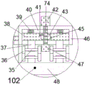
Referring to fig. 1-7, an embodiment of the present invention is shown: a combined teaching drawing instrument special for science in class comprises a long plate 21, wherein a lifting chute 23 is arranged in the long plate 21, the lifting chute 23 is provided with a driving device 101, the driving device 101 comprises a lifting motor 31 fixedly installed on the bottom wall of the lifting chute 23, a lead screw 22 rotatably connected with the top wall of the lifting chute 23 is connected in the lifting motor 31, a threaded block 24 slidably connected with the lifting chute 23 is connected on the lead screw 22 in a threaded manner, a rotating motor 25 is fixedly arranged on the right side surface of the threaded block 24, a motor shaft 26 is connected in the rotating motor 25, a rotating block 73 is fixedly arranged on the motor shaft 26, an opening chute 72 with a rightward opening is arranged on the right side surface of the rotating block 73, a clamping block chute 29 is arranged on the bottom wall of the opening chute 72, a conical clamping block 28 is slidably connected in the clamping block chute 29, and a clamping block spring 30 is connected between the conical clamping block 28 and the clamping block chute 29, the calibration plate 27 and the elliptical plate 50 are slidably connected in the opening sliding groove 72, the conical fixture block 28 is used for fixing the calibration plate 27 and the elliptical plate 50, the right side surface of the long plate 21 is provided with a T-shaped sliding groove 32, the T-shaped sliding groove 32 is provided with a connecting device 102 used for fixing the long plate 21 and driving the long plate 21 to move back and forth, the calibration plate 27 is provided with a painting brush device 103 used for drawing circles and straight lines, and the elliptical plate 50 is provided with a composite device 104 used for drawing ellipses.
In addition, in one embodiment, the connecting device 102 includes a T-shaped sliding block 34 slidably installed in the T-shaped sliding slot 32, a connecting spring 33 is connected between the T-shaped sliding block 34 and the T-shaped sliding slot 32, a clamping plate 46 is fixedly installed on the right side surface of the T-shaped sliding block 34, an inner groove 40 with a downward opening is formed in the clamping plate 46, a long sliding plate 38 is slidably connected in the inner groove 40, return springs 39 are symmetrically connected between the long sliding plate 38 and the inner groove 40 in a left-right manner, a rotating rod 74 is rotatably connected to the top wall of the inner groove 40 and the top surface of the clamping plate 46, a rotating block 42 is fixedly installed on the top side of the rotating rod 74, the lower side of the rotating rod 74 extends downward through the long sliding plate 38 and is rotatably connected to the upper and lower side surfaces of the long sliding plate 38, a limiting block 47 is fixedly installed on the bottom side of the rotating rod, the inner wall of dead slot 43 is equipped with ring channel 45, dwang 74 is in dead slot 43 set firmly with ring channel 45 sliding connection's button head pole 41, the right flank of long board 21 has set firmly bottom plate 48, the last side of bottom plate 48 with the downside of long slide 38 bilateral symmetry respectively has set firmly support 37, four the rotation is connected with shaft 35 in the support 37, every the left and right sides of shaft 35 has set firmly wheel 36 respectively, earlier will splint 46 upwards stimulates, then will through coupling spring 33 splint 46 with bottom plate 48 fixes on the chalk groove of blackboard, then promotes long board 21, can drive through wheel 36 long board 21 removes, when needs fixed unmovable, thereby rotatory piece 42 drives dwang 74, button head pole 41 and restriction piece 47 are rotatory, the round head rod 41 rotates to drive the long sliding plate 38 to move upwards, so that the wheels 36 on the long sliding plate 38 move upwards, the limiting block 47 is abutted to the blackboard slot, and fixing is completed.
In addition, in one embodiment, the painting brush device 103 includes a corresponding groove 71 disposed on the bottom surface of the scale plate 27, the corresponding groove 71 may be slidably connected to the tapered latch 28, the left and right side surfaces of the scale plate 27 are provided with a chalk groove 49 for fixing chalk in a penetrating manner, the tapered latch 28 may be pulled downward, so that the scale plate 27 is inserted into the open sliding groove 72, then the distance between the chalk groove 49 and the motor shaft 26 may be adjusted, then the tapered latch 28 is released, so that the tapered latch 28 is latched into the corresponding groove 71, then chalk is latched into the chalk groove 49, then the rotating motor 25 is turned on, so that the motor shaft 26, the rotating block 73 and the scale plate 27 are driven to rotate, so that circle drawing is completed, the angle of the scale plate 27 is adjusted by the motor shaft 26, then a pen can be used to draw lines of varying angles along the top surface of the scale plate 27.
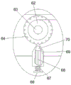
In addition, in one embodiment, the composite device 104 includes an adjusting sliding slot 54 disposed in the elliptical plate 50, another set of corresponding slots 71 is disposed on the bottom surface of the elliptical plate 50, an adjusting sliding block 75 is slidably connected in the adjusting sliding slot 54, a rectangular block 52 is fixedly disposed on the right side surface of the adjusting sliding block 75, a fixing rod 53 is fixedly disposed on the right side surface of the rectangular block 52, a pulling block 56 is disposed on the bottom surface of the rectangular block 52, symmetrical springs 55 are symmetrically connected between the pulling block 56 and the rectangular block 52 in a left-right manner, a clamping pin 57 capable of abutting against the corresponding slot 71 in the elliptical plate 50 is fixedly disposed on the top surface of the pulling block 56, a winding shaft 63 is rotatably connected on the right side surface of the elliptical plate 50, a clamping chuck 64 is fixedly disposed on the left side of the winding shaft 63, a winding wheel 62 is fixedly disposed on the right side of the winding shaft 63, a rope 51 is wound on the winding wheel 62, the other end of the rope 51 is fixedly connected with the fixed rod 53, a traverse block 60 is slidably connected with the rope 51, friction pads 59 slidably connected with the rope 51 are vertically and symmetrically fixedly arranged in the traverse block 60, a chalk block 61 is fixedly arranged on the right side surface of the traverse block 60, chalk can be fixed by the chalk block 61, a mounting block 69 is fixedly arranged on the right side surface of the elliptical plate 50, a limiting block 70 is slidably connected with the mounting block 69, a thin rod 68 is fixedly arranged on the bottom side of the limiting block 70, a small block 66 is fixedly arranged on the bottom side of the thin rod 68, a small spring 67 is connected between the small block 66 and the mounting block 69, the limiting block 70 can be abutted against the chuck 64, the tapered fixture block 28 can be pulled downwards, the elliptical plate 50 is inserted into the rotating block 73, the rightmost corresponding groove 71 is aligned with the tapered fixture block 28, and then the tapered fixture block 28 is loosened, then, the small block 66 is pulled down to drive the limiting block 70 to move downwards through the thin rod 68, then the chuck 64 is rotated by hand, so that the winding wheel 62 emits the rope 51 with the required length, then the small block 66 is loosened, then the pulling block 56 is pulled downwards, then the rectangular block 52 is pulled to the right to the required point, then the pulling block 56 is loosened, the position of the fixing rod 53 and the winding wheel 62 is determined, then chalk is inserted into the chalk block 61, then the position of the chalk block 61 on the rope 51 is adjusted, then the chalk block 61 is grasped by hand, then the rope is tightened, and then an ellipse is drawn around the winding shaft 63 and the fixing rod 53.
In addition, in one embodiment, the friction pad 59 is made of rubber, has a large friction force with the rope 51, and can move the chalk block 61 only by manually pulling the traverse block 60.
In addition, in one embodiment, the limiting block 47 is made of a magnet material, and when the limiting block 47 collides with the chalk groove, the limiting block will attract the chalk groove.
In addition, in one embodiment, the scale plate 27 is provided at both left and right sides thereof with scales aligned with the corresponding grooves 71 so as to adjust the diameter of a circle and the length of a drawn straight line.
In addition, in one embodiment, the rotating motor 25 is a low-speed motor, and the rotating speed is low, so that the chalk can be effectively prevented from being broken when the chalk is used for drawing a circle.
When drawing needs to be started, firstly, the clamping plate 46 is pulled upwards, then the clamping plate 46 and the bottom plate 48 are fixed on the chalk groove of the blackboard through the connecting spring 33, then the long plate 21 is pushed, the long plate 21 can be driven to move through the wheel 36, when the fixing is needed and the fixing is not needed, the rotating block 42 is rotated so as to drive the rotating rod 74, the round head rod 41 and the limiting block 47 to rotate, the round head rod 41 rotates to drive the long sliding plate 38 to move upwards, so that the wheel 36 on the long sliding plate 38 moves upwards, so that the limiting block 47 is abutted against the chalk groove, the fixing is completed, when the circle needs to be drawn, the long plate 21 is firstly moved to a proper position, then the lifting motor 31 is opened so as to drive the screw rod 22 to rotate, then the threaded block 24 is driven to be lifted to a proper height, then the scale plate 27 is inserted into the opening sliding groove 72, then the distance between the chalk groove, then the tapered fixture block 28 is released, so that the tapered fixture block 28 is clamped into the corresponding groove 71, then chalk is clamped into the chalk groove 49, then the rotating motor 25 is opened, the motor shaft 26, the rotating block 73 and the scale plate 27 are driven to rotate, so that circle drawing is completed, the angle of the scale plate 27 is adjusted through the motor shaft 26, then a straight line with different angles can be drawn along the top surface of the scale plate 27 by using a pen, when an ellipse is required to be drawn, the tapered fixture block 28 is pulled downwards, the elliptical plate 50 is inserted into the rotating block 73, so that the corresponding groove 71 at the rightmost side is aligned with the tapered fixture block 28, then the tapered fixture block 28 is released, then the small block 66 is pulled downwards, so that the thin rod 68 drives the limiting block 70 to move downwards, then the chuck 64 is rotated by hand, so that the winding wheel 62 emits the rope 51 with the required length, then the small block 66 is released, then the pulling block 56 is pulled downwards, and then the rectangular block 52 is pulled to, then the pulling block 56 is released to determine the position of the fixing rod 53 and the winding wheel 62, and then chalk is inserted into the chalk block 61, then the position of the chalk block 61 on the string 51 is adjusted, and then the chalk block 61 is grasped by hand, and then the string is tightened, and then an ellipse is drawn around the winding shaft 63 and the fixing rod 53.
The invention has the beneficial effects that: this device can draw not unidimensional circle and ellipse through the combination of difference, optional position on the blackboard, also can draw the straight line of different angles, compares in the big compasses that traditional blackboard was used, and this device is when drawing the circle, and the centre of a circle can not squint, and the diameter of circle also can not change, and this device has overcome the unable elliptical problem of drawing of traditional teaching instrument simultaneously, can make things convenient for more and can impart knowledge to students in the classroom.
The above description is only an embodiment of the invention, but the scope of the invention is not limited thereto, and any changes or substitutions that are not thought of through the inventive work should be included in the scope of the invention. Therefore, the protection scope of the invention should be subject to the protection scope defined by the claims.