CN1101872C - Multiple zone limiting orifice drying of cellulosic fibrous structures, apparatus thereof, and cellulosic fibrous structures produced thereby - Google Patents
Multiple zone limiting orifice drying of cellulosic fibrous structures, apparatus thereof, and cellulosic fibrous structures produced thereby Download PDFInfo
- Publication number
- CN1101872C CN1101872C CN96195746A CN96195746A CN1101872C CN 1101872 C CN1101872 C CN 1101872C CN 96195746 A CN96195746 A CN 96195746A CN 96195746 A CN96195746 A CN 96195746A CN 1101872 C CN1101872 C CN 1101872C
- Authority
- CN
- China
- Prior art keywords
- zone
- web
- nascent
- per
- drying
- Prior art date
- Legal status (The legal status is an assumption and is not a legal conclusion. Google has not performed a legal analysis and makes no representation as to the accuracy of the status listed.)
- Expired - Fee Related
Links
Images
Classifications
-
- F—MECHANICAL ENGINEERING; LIGHTING; HEATING; WEAPONS; BLASTING
- F26—DRYING
- F26B—DRYING SOLID MATERIALS OR OBJECTS BY REMOVING LIQUID THEREFROM
- F26B13/00—Machines and apparatus for drying fabrics, fibres, yarns, or other materials in long lengths, with progressive movement
- F26B13/10—Arrangements for feeding, heating or supporting materials; Controlling movement, tension or position of materials
- F26B13/101—Supporting materials without tension, e.g. on or between foraminous belts
-
- D—TEXTILES; PAPER
- D21—PAPER-MAKING; PRODUCTION OF CELLULOSE
- D21F—PAPER-MAKING MACHINES; METHODS OF PRODUCING PAPER THEREON
- D21F5/00—Dryer section of machines for making continuous webs of paper
- D21F5/02—Drying on cylinders
- D21F5/021—Construction of the cylinders
-
- D—TEXTILES; PAPER
- D21—PAPER-MAKING; PRODUCTION OF CELLULOSE
- D21F—PAPER-MAKING MACHINES; METHODS OF PRODUCING PAPER THEREON
- D21F5/00—Dryer section of machines for making continuous webs of paper
- D21F5/14—Drying webs by applying vacuum
- D21F5/143—Drying webs by applying vacuum through perforated cylinders
-
- D—TEXTILES; PAPER
- D21—PAPER-MAKING; PRODUCTION OF CELLULOSE
- D21F—PAPER-MAKING MACHINES; METHODS OF PRODUCING PAPER THEREON
- D21F5/00—Dryer section of machines for making continuous webs of paper
- D21F5/18—Drying webs by hot air
- D21F5/182—Drying webs by hot air through perforated cylinders
-
- D—TEXTILES; PAPER
- D21—PAPER-MAKING; PRODUCTION OF CELLULOSE
- D21H—PULP COMPOSITIONS; PREPARATION THEREOF NOT COVERED BY SUBCLASSES D21C OR D21D; IMPREGNATING OR COATING OF PAPER; TREATMENT OF FINISHED PAPER NOT COVERED BY CLASS B31 OR SUBCLASS D21G; PAPER NOT OTHERWISE PROVIDED FOR
- D21H13/00—Pulp or paper, comprising synthetic cellulose or non-cellulose fibres or web-forming material
-
- F—MECHANICAL ENGINEERING; LIGHTING; HEATING; WEAPONS; BLASTING
- F26—DRYING
- F26B—DRYING SOLID MATERIALS OR OBJECTS BY REMOVING LIQUID THEREFROM
- F26B13/00—Machines and apparatus for drying fabrics, fibres, yarns, or other materials in long lengths, with progressive movement
- F26B13/10—Arrangements for feeding, heating or supporting materials; Controlling movement, tension or position of materials
- F26B13/14—Rollers, drums, cylinders; Arrangement of drives, supports, bearings, cleaning
- F26B13/16—Rollers, drums, cylinders; Arrangement of drives, supports, bearings, cleaning perforated in combination with hot air blowing or suction devices, e.g. sieve drum dryers
Landscapes
- Engineering & Computer Science (AREA)
- Textile Engineering (AREA)
- Mechanical Engineering (AREA)
- General Engineering & Computer Science (AREA)
- Paper (AREA)
- Drying Of Solid Materials (AREA)
- Polysaccharides And Polysaccharide Derivatives (AREA)
- Artificial Filaments (AREA)
- Spinning Methods And Devices For Manufacturing Artificial Fibers (AREA)
Abstract
A limiting orifice through-air-drying apparatus for papermaking or other absorbent embryonic webs. The apparatus has a first zone (41) and a second zone (42). The first (41) zone is maintained at a differential pressure less than the breakthrough pressure, while the second zone (42) is maintained at a differential pressure greater than the breakthrough pressure. The residence time of the embryonic web to be dried with the apparatus is maintained at preferably less than 35 milliseconds on the first zone. Using the dual zone system described above, the overall energy required to run the apparatus can be reduced.
Description
Technical Field
The present invention relates to air-dried absorbent embryonic webs, and more particularly to air-dried cellulosic fibrous structures.
Background
Absorbent embryonic webs are a common source material. It includes cellulosic fibrous structures, absorbent foams, and the like. Cellulosic fibrous structures have become a common source of material. The fibrous tissue is used for facial tissue, toilet paper and paper towel.
In the production of cellulosic fibrous structures, a wet embryonic web comprised of cellulosic fibers dispersed in a liquid carrier is deposited onto a forming wire. The wet embryonic web may be dried by any one or a combination of well known means, each of which affects the properties of the final cellulosic web. For example, the apparatus and process of drying can affect the softness, internal diameter, tensile strength, and absorbency of the final cellulosic fibrous structure. Likewise, the apparatus and method used to dry the cellulosic fibrous structure also affects the rate of production of the fibrous tissue.
Felt belts are one type of device used for drying. Felt drying belts have long been used for dewatering virgin cellulosic fibrous structures by allowing capillary flow of the liquid carrier from the cellulosic fibrous structure into a permeable felt medium held in contact with the virgin fabric. However, dewatering with felt strips results in the dried raw cellulosic fibrous web being subjected to the same pressure and the same shrinkage throughout the drying process.
The felt drying can be by means of vacuum or also by means of opposed press rolls. The press rolls increase the mechanical pressure of the cellulosic fibrous structure against the felt. Examples of felt drying are described in U.S. Pat. No. 4,329,201 issued on month 11 of 1982 to Bolton, and U.S. Pat. No. 4,888,096 issued on month 12 of 1989 to Cowan et al.
Drying cellulosic fibrous structures by vacuum dewatering without the use of felt is also well known in the art. Vacuum dewatering of the cellulosic fibrous structure mechanically extracts the liquid moisture from the cellulosic fibrous structure. The vacuum also biases the discrete regions of the cellulosic fibrous structure to the deflection conduits of the drying belt so that different regions of the cellulosic fibrous structure have different moisture contents. Similarly, the drying of cellulosic fibrous structures by vacuum assisted capillary flow using a perforated cylinder with preferred apertures is also well known in the art. Examples of such vacuum driven drying techniques are shown in us patent 4,556,450 issued to Chuang on month 12 and 27 of 1985, and us patent 4,973,385 issued to Jean et al on month 11 and 27 of 1990.
Another method of air drying the original cellulosic fibrous structure has also met with great success. In a typical through-air drying process, a porous through-air belt supports the embryonic web to be dried. The hot air stream passes through the cellulose fibers and then through the air permeable belt, and vice versa. The air stream dries the embryonic web primarily by evaporation. The areas coinciding with or offset from the air permeable belt pores are dried well and the inner diameter of the final cellulosic fibrous structure is increased. While the area coinciding with the joint area in the permeable belt is less dry.
Several improvements to air permeable belts for through-air drying have been made in the field. For example, the permeable belt can be made with a large open face (at least 40%). Or the breathable band may be made to have low breathability. The air permeability of the belt can be reduced by blocking the woven yarn gaps in the belt with a blended resin. The drying belt may also incorporate metal particles to increase its thermal conductivity to reduce its radiation power, or the drying belt may be made of a photosensitive resin having a continuous network. The drying belt is particularly suited for high temperature airflows that can reach 815 degrees celsius (1500 degrees fahrenheit). Examples of such through-air drying techniques are disclosed in U.S. Pat. No. Re.28,459 to Cole et al, 7/1 1975; U.S. Pat. No. 4,172,910 issued to Rotar at 30/10 in 1979, and U.S. Pat. No. 4,251,928 issued to Rotar et al at 24/2 in 1981; well known U.S. Pat. No. 4,528,239 issued to Trokhan on 7/9 of 1985; and U.S. Pat. No. 4,921,750 issued to Todd on 5/1 of 1990. In addition, attempts have been made in the art to adjust the dry shape of the fibrous structure while the cellulosic fibrous structure is still in the embryonic web and is to be dried. This attempt utilized a drying belt or an infrared dryer in combination with a Yankee hood (Yankee hood). Examples of shape-modified drying are described in U.S. Pat. No. 4,583,302 issued at 22.4.1986 to Smith and U.S. Pat. No. 4,942,675 issued at 24.7.1990 to Sundovist.
The technology, even through-air drying, does not address the problems encountered in multi-zone drying of cellulosic fibrous structures. For example, a first region of a cellulosic fibrous structure having relatively less absolute moisture, density, or specific gravity than a second region will generally have a greater airflow therethrough than the second region. This relatively large airflow occurs because the first region, which has relatively little absolute moisture, density or specific gravity, exhibits correspondingly less damping against airflow through that region.
This problem is particularly acute when the multi-region cellulosic fibrous structure to be dried is conveyed to a yankee drying drum. On a yankee drying drum, isolated, discrete regions of cellulosic fibrous structure are brought into close proximity with the circumference of a heated cylinder, and heated air from a hood is directed onto the cellulosic fibrous surface in engagement with the heated cylinder. However, the tightest area that is typically in contact with the yankee dryer drum is an area of high density or high specific gravity that does not dry as well as an area of low density or low specific gravity. In the low density zone, the best drying results are achieved by air flow heat exchange within the yankee drying drum hood. Thus, the efficiency of the production of the cellulosic fibrous structure must be reduced in order to compensate for the greater moisture content in the high density or high specific gravity regions. To completely dry the high density and high specific gravity regions of the cellulosic fibrous structure while preventing the hot air from the hood from scorching or burning out the already dried low density or low specific gravity regions, the air temperature of the yankee hood must be reduced, and the residence time of the cellulosic fibrous structure within the yankee hood must be increased, thereby reducing production efficiency.
Another disadvantage of the prior art in this field (other than those using mechanical pressure, such as felt belts) is that each method uses a method of supporting the cellulosic fibrous structure and drying it. The air stream is directed toward the cellulosic fibrous structure and through a support belt or, alternatively, the air stream is passed through a drying belt into the cellulosic fibrous structure. The differential air flow damping through the cellulosic fibrous structure or through the drying belt increases the difference in moisture distribution within the cellulosic fibrous structure and/or creates a moisture distribution differential that was not present. However, there have been no attempts in the art to adapt the gas flow to different regions of the cellulosic fibrous structure.
An improvement in this art which addresses this problem is disclosed in U.S. Pat. No. 5,274,930 to Ensign et al, 1/4 of 1994, which discloses a combination of limiting pore drying and through-air drying of cellulose fibers and is incorporated herein by reference. This patent relates to an apparatus that utilizes a microporous drying medium having greater flow damping than the gaps in the cellulosic fibrous structure. Thus, the microporous media is a limiting pore in a through-air drying process that achieves an equal or more uniform moisture distribution during the drying process.
The restricted orifice through-air drying apparatus invented by Enslgn et al relates to one or more zones having positive or negative pressure that may encourage airflow in different directions.
This patent (8: 17-26) shows that as the specific gravity of the initial web increases, the residence time on the microporous medium will, by reason, need to be longer. In particular, it shows that the specific gravity of typical facial tissue (5.44 kilograms (12 pounds) per 270 square meters (3,000 square feet)) requires a residence time on the microporous media of at least about 250 milliseconds.
The inventors have surprisingly found that the required residence time in the first zone can be reduced, with the problem that the pore-defining through-air drying device can be divided into a plurality of zones. Furthermore, it has been surprisingly found that the use of suitable areas reduces the overall energy consumption of the device. In particular, if the size and selection of the zones is appropriate, less fan kilowatts (horsepower) is required. By using the present invention, the fan kilowatts (horsepower) can be reduced by ten to fifteen percent over the original device invented by design et al. The potential savings are considerable in the view of the annual published operating costs of $200 to $250 per 0.75 kilowatts (horsepower).
Disclosure of Invention
It is therefore an object of the present invention to provide a limiting orifice through-air-drying apparatus with a micropore medium for through-air drying for processing cellulosic fibrous structures. It is another object of the present invention to provide a restricted orifice through-air drying apparatus that reduces the residence time and energy consumption required by the prior art.
The present invention includes a limiting orifice through-air drying apparatus and an embryonic web having a moisture profile contained therein. The embryonic web can comprise a cellulosic fibrous structure. The embryonic web has a density of at least eighteen percent. The device further comprises a set of distinct zones, in order of which there should be at least a first zone and a second zone. The regions have mutually different pressures with respect to atmospheric pressure.
In one embodiment, the apparatus has a dewatering rate in the second zone of at least 5 kilograms (5 pounds) of water per second per kilogram (pounds) of embryonic web. In a second embodiment, the apparatus has a dewatering rate in the second zone of at least 0.1 times that of the first zone and a dewatering rate in the second zone of at least 5 kilograms (5 pounds) of water per second per kilogram (pounds) of embryonic web. In a third embodiment, the apparatus has a residence time in the first zone of less than about 35 milliseconds.
Drawings
Embodiments of the present invention are described in detail below with reference to the accompanying drawings. Wherein,
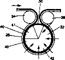
FIG. 1 is a side view schematic of the operation of a micropore medium incorporating a gas permeable cylinder having a negative pressure therein according to the present invention;
FIG. 2 is a graph of density versus residence time on the apparatus of the present invention;
FIG. 3 is a graph of energy consumption and dewatering versus time (CC) for the present invention, a graph of a prior art micropore drying apparatus (BB), and a graph of this prior Art Apparatus (AA) according to well known U.S. Pat. No. 4,556,450(1985, 12, granted to Chuang et al, 3).
Detailed Description
Referring to fig. 1, the present invention includes a limiting orifice through-air-drying device 20 and a micropore medium 30. The device 20 and media 30 may be made as described in U.S. patent 5,274,930, which is incorporated herein by reference. The device 20 includes a gas permeable cartridge 32 and a microporous media 30 circumscribing the gas permeable cartridge 32. A support 28, such as a through-air drying belt, wraps the air cylinder 32 from the entrance roll 34 to the exit roll 36, corresponding to a circular arc segment 40. The circular arc segment 40 can be subdivided into a plurality of zones 41, 42 having mutually different pressures with respect to the atmospheric pressure. Alternatively, the apparatus 20 may include an isolated vacuum tank or endless belt. The apparatus 20 removes water from the embryonic web.
The limiting orifice through air drying apparatus 20 according to the present invention may be divided into a plurality of zones. Preferably, the device 20 has two regions, a first region 41 and a second region 42. The embryonic web passes through the first zone 41, through the second zone 42, and through the other zones in sequence, if any. The first zone 41 is maintained at a lower gas pressure than the penetration pressure of the device 20. While the second zone 42 maintains a gas pressure higher than the penetration pressure of the device 20. The breakthrough pressure was established according to the space recommendation convention 901 promulgated by the automated engineering society on 3/1/1968 and designated as the bubble point test method modified to use a pressure of 50 mm penetration depth, which example is incorporated herein by reference.
The first region 41 and the second region 42 together subtend an arc of about 180 to 270 degrees, more preferably 210 to 240 degrees. The first region 41 encompasses up to 60 degrees, more preferably 20 to 30 degrees, of the arc subtended by the entire first region 41 and second region 42.
The support member 28 transfers the absorbent embryonic web to the apparatus 20 and causes the embryonic web to pass through the zones 41, 42 at a rate such that the residence time in the first zone 41 is less than 35 milliseconds, preferably less than 25 milliseconds, and more preferably less than 15 milliseconds. The time taken to pass through the second zone 42 should be at least 125 milliseconds, and preferably 175 milliseconds.
As used herein, an "absorbent embryonic web" comprises a cellulosic fibrous structure or other fabric having a wet deposit and which must be dewatered to a dry state for use. "hygroscopic" as used herein means capable of retaining or retaining moisture or capable of removing moisture from a surface. As used herein, "cellulosic fibrous structure" refers to a structure such as paper containing at least fifty percent cellulosic fibers and synthetic fibers, organic fillers, inorganic filler foams, and the like. Suitable cellulosic fibrous structures for use in the present invention can be found in well known U.S. Pat. No. 5,245,025, issued 9/14 1993 to Trokhan et al, which is incorporated herein by reference.
By providing two distinct zones 41, 42, the first zone 41 having a pressure less than the breakthrough pressure of the limiting orifice drying means 20 and the second zone 42 having a pressure greater than the breakthrough pressure of the limiting orifice drying means 20 during said dwell time, it was found that the required fan power for providing the distinct pressures was significantly reduced. The inventors have unexpectedly found that increasing the residence time in the first zone 41 does not result in a significant increase in the degree of dryness and density, as shown in figure 2.
By judicious choice of the residence time in the first zone 41 and then transfer of the embryonic web to the second zone 42, the efficiency of the drying process can be maximized and the fan power reduced. For the invention described and claimed herein, the dewatering rate of the apparatus 20 in the second zone is at least 5 kilograms (5 pounds) and preferably 7 kilograms (7 pounds) per second of dewatering per kilogram (pound) of embryonic web.
The ideal transition point between the first zone 41 and the second zone 42 is the point where the dewatering rate of the second zone 42 exceeds the dewatering rate of the first zone 41. The actual transition point is the point at which the pressure (different from atmospheric pressure) through the device 20 goes from less than the breakthrough pressure to greater than the breakthrough pressure. The best case of this system is that the actual transit point coincides with the ideal transit point. It is known that the transition point is related to the porosity of the embryonic web, drainage capacity, micropore medium flow characteristics and pore size, among other factors.
The second zone 42 may be divided into one or more sub-zones, each zone having a dedicated fan, or a large fan if desired. In addition, a single zone 41 or 42 may be generated by two or more fans at different pressures. The fans may be installed in series or in parallel. It is generally considered consistent with the present invention that the effect is the same when the total power of two smaller fans and one larger fan is the same.
Since it passes through the first zone 41 at a pressure below the breakthrough pressure, it does not require a fan and the vacuum pump can be used well. Thus, according to the present invention, the first region 41 will consume very little power on the device 20. The power referred to herein relates only to the power required to generate the differential pressure at the apparatus 20 and does not include the power required to transfer the embryonic web to the apparatus 20.
For the invention described and claimed herein, the ratio of the drying rate of the second zone 42 to the drying rate of the first zone 41, i.e., the water removed per second per unit of 0.75 kilowatts (horsepower) per 0.45 kilogram (pound) of embryonic web, is at least 0.1, and preferably at least 0.12. Of course, this ratio may be artificially increased due to inefficient operation in the first zone 41. It is an object of the present invention to provide a dewatering rate of the first zone 41 of at least 40 kilograms (40 pounds) per second of dewatering per kilogram (pounds) of embryonic web. Because the first zone 41 is capillary dewatered at a pressure below the breakthrough pressure, rather than a fan to generate a flow of air above the breakthrough pressure, the power required to dewater the first zone at this dewatering rate is minimal.
The residence time is advantageous for incipient paper webs having a pulp penetration damping (PFR) of 5 to 20, more advantageously 10 to 11. Measurement of pulp penetration damping is according to the method disclosed in well known U.S. patent 5,228,954 (Vinson et al, 7/20/1993), which is incorporated herein by reference.
Referring to fig. 2, the change in drying rate of the first zone is related to PFR and the drying rate of the second zone 42 is the same for all three curves A, B and C. The PFR of curves A, B and C shown in fig. 2 sequentially increases.
In general, it has been found that the optimum residence time on the apparatus 20 is directly proportional to the pulp penetration damping. The incoming embryonic web has a density of at least eighteen percent, and possibly at least nineteen percent.
The device 20 according to the invention has a higher dewatering capacity at a given pulp penetration damping than the existing, known (the description of which is found in us patent 4,556,450 issued to Chuang on 3.12.1985) technique of drying fabrics by suction through capillary tubes and maintaining the fabric under a state of less than the penetration pressure, said known patent being incorporated herein by reference; including a prior art woven support 28, a prior art photosensitive resin support 28.
The dewatering rate is the number of kilograms (pounds) of water removed per kilogram (pounds) of fiber during the drying process divided by the time required for the process.
Percent dewatering (kg (pounds) dewatered/kg (pounds) fiber/time (seconds)
The dewatering rate is determined by measuring the density of the embryonic web before and after the zones 41, 42 when the fully dried condition is achieved by gravity repressurization and convection drying. The dead time can be easily calculated after knowing the path length and speed of the embryonic web through the zones 41, 42.
Referring to fig. 3, it is noted that the dewatering rate of the apparatus according to the invention in zone 2 is significantly higher than that of the cylinder dryer technique of Chuang et al.
In the second zone 42, the dewatering rate of the apparatus 20 according to the present invention is at least 5 kilograms (5 pounds) per second of embryonic web, and more preferably at least 7 kilograms (7 pounds) per second of embryonic web. In the first zone 41, the dewatering rate of the apparatus 20 according to the present invention is at least 40 kilograms (40 pounds) per second of the embryonic web, and more preferably at least 50 kilograms (50 pounds) per second of the embryonic web.
In the first zone 41, the apparatus 20 according to the present invention consumes less than 3.73 kilowatts (5 horsepower), and more preferably less than 2.98 kilowatts (4 horsepower), of power per 0.09 square meters (one square foot) of fabric processed as the embryonic web is processed. In the second zone 42, the power required by the apparatus 20 according to the present invention is less than 13.43 kilowatts (18 horsepower), and more preferably less than 11.94 kilowatts (16 horsepower), per 0.09 square meters (one square foot) of fabric being processed.
Claims (10)
Applications Claiming Priority (6)
| Application Number | Priority Date | Filing Date | Title |
|---|---|---|---|
| US08/475,284 | 1995-06-07 | ||
| US08/486,874 US5581906A (en) | 1995-06-07 | 1995-06-07 | Multiple zone limiting orifice drying of cellulosic fibrous structures apparatus therefor, and cellulosic fibrous structures produced thereby |
| US08/475,284 US5584128A (en) | 1995-06-07 | 1995-06-07 | Multiple zone limiting orifice drying of cellulosic fibrous structures, apparatus therefor, and cellulosic fibrous structures produced thereby |
| US08/484,734 | 1995-06-07 | ||
| US08/484,734 US5539996A (en) | 1995-06-07 | 1995-06-07 | Multiple zone limiting orifice drying of cellulosic fibrous structures, apparatus therefor, and cellulosic fibrous structures produced thereby |
| US08/486,874 | 1995-06-07 |
Publications (2)
| Publication Number | Publication Date |
|---|---|
| CN1192255A CN1192255A (en) | 1998-09-02 |
| CN1101872C true CN1101872C (en) | 2003-02-19 |
Family
ID=27413317
Family Applications (1)
| Application Number | Title | Priority Date | Filing Date |
|---|---|---|---|
| CN96195746A Expired - Fee Related CN1101872C (en) | 1995-06-07 | 1996-06-03 | Multiple zone limiting orifice drying of cellulosic fibrous structures, apparatus thereof, and cellulosic fibrous structures produced thereby |
Country Status (17)
| Country | Link |
|---|---|
| EP (1) | EP0865534B1 (en) |
| JP (1) | JPH11507417A (en) |
| KR (1) | KR100291880B1 (en) |
| CN (1) | CN1101872C (en) |
| AT (1) | ATE197330T1 (en) |
| AU (1) | AU721236B2 (en) |
| BR (1) | BR9609010A (en) |
| CA (1) | CA2223773C (en) |
| CZ (1) | CZ9703964A3 (en) |
| DE (1) | DE69610855T2 (en) |
| ES (1) | ES2151169T3 (en) |
| HU (1) | HUP9901098A3 (en) |
| MX (1) | MX9709814A (en) |
| NO (1) | NO975658L (en) |
| NZ (1) | NZ310350A (en) |
| TR (1) | TR199701564T1 (en) |
| WO (1) | WO1996041053A1 (en) |
Families Citing this family (3)
| Publication number | Priority date | Publication date | Assignee | Title |
|---|---|---|---|---|
| EP1785523A3 (en) * | 2001-08-14 | 2007-05-30 | The Procter and Gamble Company | Through-air drying apparatus having decreasing wet flow resistance in the machine direction and process of drying a web therewith |
| DE102011113837A1 (en) * | 2011-09-21 | 2013-03-21 | Trützschler Nonwovens Gmbh | Heating system for heating a gaseous treatment medium for a dryer |
| CN103954110A (en) * | 2014-03-28 | 2014-07-30 | 吴江龙升纺织有限公司 | Penetration type drying device for textile |
Citations (2)
| Publication number | Priority date | Publication date | Assignee | Title |
|---|---|---|---|---|
| US4074441A (en) * | 1976-03-08 | 1978-02-21 | Frederick D. Helversen | Rotary through dryer having multiple vacuum chambers and associated heaters |
| US5274930A (en) * | 1992-06-30 | 1994-01-04 | The Procter & Gamble Company | Limiting orifice drying of cellulosic fibrous structures, apparatus therefor, and cellulosic fibrous structures produced thereby |
Family Cites Families (5)
| Publication number | Priority date | Publication date | Assignee | Title |
|---|---|---|---|---|
| FR1334777A (en) * | 1961-10-02 | 1963-08-09 | Fleissner Gmbh | Method and device for the treatment of wet or damp materials, in particular with a view to their drying |
| US3265559A (en) * | 1965-05-03 | 1966-08-09 | Time Inc | Paper press section |
| USRE28459E (en) * | 1966-06-07 | 1975-07-01 | Transpiration drying and embossing of wet paper webs | |
| DE3141460A1 (en) * | 1981-10-19 | 1983-05-05 | Brückner-Apparatebau GmbH, 6120 Erbach | Perforated cylinder |
| US4556450A (en) * | 1982-12-30 | 1985-12-03 | The Procter & Gamble Company | Method of and apparatus for removing liquid for webs of porous material |
-
1996
- 1996-06-03 HU HU9901098A patent/HUP9901098A3/en unknown
- 1996-06-03 CZ CZ19973964A patent/CZ9703964A3/en unknown
- 1996-06-03 NZ NZ310350A patent/NZ310350A/en unknown
- 1996-06-03 ES ES96918490T patent/ES2151169T3/en not_active Expired - Lifetime
- 1996-06-03 DE DE69610855T patent/DE69610855T2/en not_active Expired - Lifetime
- 1996-06-03 CN CN96195746A patent/CN1101872C/en not_active Expired - Fee Related
- 1996-06-03 JP JP9502276A patent/JPH11507417A/en not_active Withdrawn
- 1996-06-03 KR KR1019970709086A patent/KR100291880B1/en not_active Expired - Fee Related
- 1996-06-03 BR BR9609010A patent/BR9609010A/en not_active IP Right Cessation
- 1996-06-03 AT AT96918490T patent/ATE197330T1/en not_active IP Right Cessation
- 1996-06-03 AU AU61134/96A patent/AU721236B2/en not_active Ceased
- 1996-06-03 CA CA002223773A patent/CA2223773C/en not_active Expired - Fee Related
- 1996-06-03 TR TR97/01564T patent/TR199701564T1/en unknown
- 1996-06-03 EP EP96918490A patent/EP0865534B1/en not_active Expired - Lifetime
- 1996-06-03 WO PCT/US1996/010303 patent/WO1996041053A1/en not_active Ceased
-
1997
- 1997-12-05 MX MX9709814A patent/MX9709814A/en active IP Right Grant
- 1997-12-05 NO NO975658A patent/NO975658L/en not_active Application Discontinuation
Patent Citations (3)
| Publication number | Priority date | Publication date | Assignee | Title |
|---|---|---|---|---|
| US4074441A (en) * | 1976-03-08 | 1978-02-21 | Frederick D. Helversen | Rotary through dryer having multiple vacuum chambers and associated heaters |
| US5274930A (en) * | 1992-06-30 | 1994-01-04 | The Procter & Gamble Company | Limiting orifice drying of cellulosic fibrous structures, apparatus therefor, and cellulosic fibrous structures produced thereby |
| WO1994000636A1 (en) * | 1992-06-30 | 1994-01-06 | The Procter & Gamble Company | Limiting orifice drying of cellulosic fibrous structures, apparatus therefor, and cellulosic fibrous structures produced thereby |
Also Published As
| Publication number | Publication date |
|---|---|
| JPH11507417A (en) | 1999-06-29 |
| NO975658L (en) | 1998-02-09 |
| CZ9703964A3 (en) | 2001-11-14 |
| AU6113496A (en) | 1996-12-30 |
| HUP9901098A3 (en) | 1999-11-29 |
| KR19990022605A (en) | 1999-03-25 |
| MX9709814A (en) | 1998-08-30 |
| ATE197330T1 (en) | 2000-11-15 |
| CA2223773A1 (en) | 1996-12-19 |
| CN1192255A (en) | 1998-09-02 |
| CA2223773C (en) | 2001-10-16 |
| AU721236B2 (en) | 2000-06-29 |
| EP0865534A1 (en) | 1998-09-23 |
| HUP9901098A2 (en) | 1999-07-28 |
| DE69610855T2 (en) | 2001-05-10 |
| BR9609010A (en) | 1999-06-29 |
| NO975658D0 (en) | 1997-12-05 |
| DE69610855D1 (en) | 2000-12-07 |
| EP0865534B1 (en) | 2000-11-02 |
| NZ310350A (en) | 2000-03-27 |
| ES2151169T3 (en) | 2000-12-16 |
| WO1996041053A1 (en) | 1996-12-19 |
| KR100291880B1 (en) | 2001-06-01 |
| TR199701564T1 (en) | 1998-03-21 |
Similar Documents
| Publication | Publication Date | Title |
|---|---|---|
| US5581906A (en) | Multiple zone limiting orifice drying of cellulosic fibrous structures apparatus therefor, and cellulosic fibrous structures produced thereby | |
| US5274930A (en) | Limiting orifice drying of cellulosic fibrous structures, apparatus therefor, and cellulosic fibrous structures produced thereby | |
| EP0915201B1 (en) | Method in the drying of a paper web and dryer section in a paper machine | |
| CN1148886A (en) | Capillary dewatering method and apparatus | |
| US20030033727A1 (en) | Method of drying fibrous structures | |
| US5539996A (en) | Multiple zone limiting orifice drying of cellulosic fibrous structures, apparatus therefor, and cellulosic fibrous structures produced thereby | |
| US3925906A (en) | Hot wire drying | |
| US20100206505A1 (en) | Method and apparatus for drying of fibrous webs | |
| US10745858B1 (en) | Through-air drying apparatus and methods of manufacture | |
| CN1101872C (en) | Multiple zone limiting orifice drying of cellulosic fibrous structures, apparatus thereof, and cellulosic fibrous structures produced thereby | |
| US5584128A (en) | Multiple zone limiting orifice drying of cellulosic fibrous structures, apparatus therefor, and cellulosic fibrous structures produced thereby | |
| EP1012389B1 (en) | Reduced surface energy limiting orifice drying medium, process of making, and process of making paper therewith | |
| HUP0002671A2 (en) | Limiting orifice drying medium, apparatus therefor, and cellulosic fibrous structures produced thereby | |
| KR20000069390A (en) | Method of and apparatus for drying a fiber web | |
| FI87587C (en) | ANORDING FROM THE CELLULOSE OF THE CELLULOSE | |
| CN1278881A (en) | Process of reducing wet pressure drop in a limiting orifice drying medium and a limiting orifice drying medium made thereby | |
| HK1013122B (en) | Limiting orifice drying of cellulosic fibrous structures, apparatus therefor, and cellulosic fibrous structures produced thereby | |
| MXPA00002408A (en) | Reduced surface energy limiting orifice drying medium, process of making, and process of making paper therewith |
Legal Events
| Date | Code | Title | Description |
|---|---|---|---|
| C06 | Publication | ||
| PB01 | Publication | ||
| C10 | Entry into substantive examination | ||
| SE01 | Entry into force of request for substantive examination | ||
| C14 | Grant of patent or utility model | ||
| GR01 | Patent grant | ||
| C19 | Lapse of patent right due to non-payment of the annual fee | ||
| CF01 | Termination of patent right due to non-payment of annual fee |