CN110299563B - Cell processing device and cell flattening mechanism - Google Patents

Cell processing device and cell flattening mechanism Download PDF

Info

Publication number
CN110299563B
CN110299563B CN201810235457.9A CN201810235457A CN110299563B CN 110299563 B CN110299563 B CN 110299563B CN 201810235457 A CN201810235457 A CN 201810235457A CN 110299563 B CN110299563 B CN 110299563B
Authority
CN
China
Prior art keywords
cell
flattening mechanism
pressing plate
motor
screw
Prior art date
Legal status (The legal status is an assumption and is not a legal conclusion. Google has not performed a legal analysis and makes no representation as to the accuracy of the status listed.)
Active
Application number
CN201810235457.9A
Other languages
Chinese (zh)
Other versions
CN110299563A (en
Inventor
徐鸿俊
李根发
曾耿
Current Assignee (The listed assignees may be inaccurate. Google has not performed a legal analysis and makes no representation or warranty as to the accuracy of the list.)
Huizhou Yakang Precision Machinery Co.,Ltd.
Original Assignee
Dongguan Yakang Precision Machinery Co Ltd
Priority date (The priority date is an assumption and is not a legal conclusion. Google has not performed a legal analysis and makes no representation as to the accuracy of the date listed.)
Filing date
Publication date
Application filed by Dongguan Yakang Precision Machinery Co Ltd filed Critical Dongguan Yakang Precision Machinery Co Ltd
Priority to CN201810235457.9A priority Critical patent/CN110299563B/en
Publication of CN110299563A publication Critical patent/CN110299563A/en
Application granted granted Critical
Publication of CN110299563B publication Critical patent/CN110299563B/en
Active legal-status Critical Current
Anticipated expiration legal-status Critical

Links

Images

Classifications

    • H—ELECTRICITY
    • H01—ELECTRIC ELEMENTS
    • H01M—PROCESSES OR MEANS, e.g. BATTERIES, FOR THE DIRECT CONVERSION OF CHEMICAL ENERGY INTO ELECTRICAL ENERGY
    • H01M10/00—Secondary cells; Manufacture thereof
    • H01M10/04—Construction or manufacture in general
    • H01M10/0404—Machines for assembling batteries
    • H01M10/0409—Machines for assembling batteries for cells with wound electrodes
    • H—ELECTRICITY
    • H01—ELECTRIC ELEMENTS
    • H01M—PROCESSES OR MEANS, e.g. BATTERIES, FOR THE DIRECT CONVERSION OF CHEMICAL ENERGY INTO ELECTRICAL ENERGY
    • H01M10/00—Secondary cells; Manufacture thereof
    • H01M10/04—Construction or manufacture in general
    • H01M10/0431—Cells with wound or folded electrodes
    • H—ELECTRICITY
    • H01—ELECTRIC ELEMENTS
    • H01M—PROCESSES OR MEANS, e.g. BATTERIES, FOR THE DIRECT CONVERSION OF CHEMICAL ENERGY INTO ELECTRICAL ENERGY
    • H01M10/00—Secondary cells; Manufacture thereof
    • H01M10/05—Accumulators with non-aqueous electrolyte
    • H01M10/058—Construction or manufacture
    • Y—GENERAL TAGGING OF NEW TECHNOLOGICAL DEVELOPMENTS; GENERAL TAGGING OF CROSS-SECTIONAL TECHNOLOGIES SPANNING OVER SEVERAL SECTIONS OF THE IPC; TECHNICAL SUBJECTS COVERED BY FORMER USPC CROSS-REFERENCE ART COLLECTIONS [XRACs] AND DIGESTS
    • Y02—TECHNOLOGIES OR APPLICATIONS FOR MITIGATION OR ADAPTATION AGAINST CLIMATE CHANGE
    • Y02E—REDUCTION OF GREENHOUSE GAS [GHG] EMISSIONS, RELATED TO ENERGY GENERATION, TRANSMISSION OR DISTRIBUTION
    • Y02E60/00—Enabling technologies; Technologies with a potential or indirect contribution to GHG emissions mitigation
    • Y02E60/10—Energy storage using batteries
    • Y—GENERAL TAGGING OF NEW TECHNOLOGICAL DEVELOPMENTS; GENERAL TAGGING OF CROSS-SECTIONAL TECHNOLOGIES SPANNING OVER SEVERAL SECTIONS OF THE IPC; TECHNICAL SUBJECTS COVERED BY FORMER USPC CROSS-REFERENCE ART COLLECTIONS [XRACs] AND DIGESTS
    • Y02—TECHNOLOGIES OR APPLICATIONS FOR MITIGATION OR ADAPTATION AGAINST CLIMATE CHANGE
    • Y02P—CLIMATE CHANGE MITIGATION TECHNOLOGIES IN THE PRODUCTION OR PROCESSING OF GOODS
    • Y02P70/00—Climate change mitigation technologies in the production process for final industrial or consumer products
    • Y02P70/50—Manufacturing or production processes characterised by the final manufactured product

Landscapes

  • Engineering & Computer Science (AREA)
  • Manufacturing & Machinery (AREA)
  • Chemical & Material Sciences (AREA)
  • Chemical Kinetics & Catalysis (AREA)
  • Electrochemistry (AREA)
  • General Chemical & Material Sciences (AREA)
  • Battery Mounting, Suspending (AREA)
  • Battery Electrode And Active Subsutance (AREA)

Abstract

本发明提出一种电芯加工装置及电芯压扁机构,该电芯压扁机构包括:底座,装设该底座上用于承托待压扁的电芯的压座,装设在该底座上的多根导柱,装设在这些导柱上并且受驱能够上下动作的压板,用于驱动该压板动作的电机和传动单元,以及用于测量该压板与该底座之间待压扁的电芯所承受压力大小的压力传感器;该电机受控于该压力传感器给出的压力信号。压力控制可靠。

Figure 201810235457

The present invention provides a cell processing device and a cell flattening mechanism. The cell flattening mechanism includes: a base, on which a pressing seat for supporting a cell to be flattened is installed, and is installed on the base A plurality of guide pillars on the upper part, a pressing plate installed on these guide pillars and driven to move up and down, a motor and a transmission unit for driving the operation of the pressing plate, and a measuring plate to be flattened between the pressing plate and the base The pressure sensor of the pressure on the cell; the motor is controlled by the pressure signal given by the pressure sensor. Reliable pressure control.

Figure 201810235457

Description

Electricity core processingequipment and electricity core flattening mechanism
Technical Field
The invention relates to a battery cell processing device, in particular to a battery cell flattening mechanism for flattening a battery cell.
Background
Taking winding processing of a lithium battery cell as an example, a conventional battery cell processing apparatus is generally provided with a cell flattening mechanism for flattening the battery cell. Referring to fig. 1 and 2, a conventional cell flattening mechanism 10a fixed to a wall plate 1a generally includes: the guide post 2a, a pressing base 3a attached to the tip of the guide post 2a, a pressing plate 13a attached to the guide post 2a via a linear bearing 7a, and a pneumatic cylinder 9a for driving the pressing plate 13a to move up and down. When the cell 50a to be flattened is supported on the pressing plate 13a, and the pressing plate 13a is driven by the air compression cylinder 9a to move upwards, the cell 50a to be flattened is pressed by the clamping action of the pressing plate 13a and the pressing base 3a, so as to be flattened. In this way, the air cylinder 9a applies pressure to the battery cell 50a to be flattened from the bottom, and the air pressure is adjusted by the electric proportional valve to control the magnitude of the pressure, which has some disadvantages: open loop pressure control, resulting in unreliable pressure control; in addition, the occupied space in the vertical direction is large.
Disclosure of Invention
The invention aims to solve the technical problem of overcoming the defects in the prior art, and provides a cell flattening mechanism with reliable pressure control.
The invention provides a cell flattening mechanism aiming at the technical problem, which comprises: the device comprises a base, a pressing seat, a plurality of guide posts, a pressing plate, a motor, a transmission unit and a pressure sensor, wherein the pressing seat is arranged on the base and used for bearing an electric core to be flattened; the motor is controlled by a pressure signal given by the pressure sensor.
In some embodiments, the motor is a servo motor; the transmission unit comprises a driving synchronous wheel driven by the motor and a driven synchronous wheel connected with the driving synchronous wheel through a synchronous belt.
In some embodiments, the transmission unit further comprises a lead screw nut driven by the driven synchronizing wheel to rotate and a lead screw driven by the lead screw nut to rotate; wherein, this clamp plate and this lead screw fixed connection.
In some embodiments, the transmission unit further comprises a screw rotation preventing structure matched with the screw rod and used for fixing the screw rod to be not rotated but not influencing the linear motion of the screw rod along the vertical direction.
In some embodiments, the screw rotation prevention structure is achieved by a cam follower.
In some embodiments, there are four guide posts, and four corners of the pressing plate are symmetrically arranged on the four guide posts; the four guide posts are symmetrically arranged at four corners of the bottom plate.
In some embodiments, the motor is mounted on the mounting plate.
In some embodiments, the device further comprises a limit detection unit matched with the pressing plate and used for detecting whether the up-and-down motion of the pressing plate reaches a set position.
In some embodiments, the position detection unit includes a vertically extending mounting rod fixed to the base plate, an upper position detection member and a lower position detection member mounted on the mounting rod; the upper limit detection piece is used for detecting the action of the pressing plate to a high position, and the lower limit detection piece is used for detecting the action of the pressing plate to a low position.
The invention also provides a battery cell processing device aiming at the technical problem, which comprises the battery cell flattening mechanism.
Compared with the prior art, the cell processing device and the cell flattening mechanism have the advantages that the configuration of the motor pressure sensor is skillfully adopted, the closed-loop control of the pressure can be realized, the response is fast, the pressure output is accurate and stable, no impact exists, and the pressure control is reliable.
Drawings
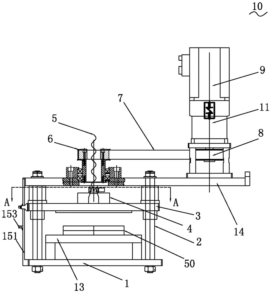
Fig. 1 and 2 illustrate a cell flattening mechanism in two different states.
Fig. 3, 4 and 5 are structural schematic diagrams of the cell flattening mechanism of the present invention from three different viewing angles.
Fig. 6 and 7 illustrate the cell flattening mechanism of the present invention in two different states.
Fig. 8 is a sectional view showing the structure of a-a in fig. 6.
Wherein the reference numerals are as follows: 10a, a cell flattening mechanism 1a, a wall plate 2a, a guide pillar 3a, a pressing seat 7a, a linear bearing 9a, an air compression cylinder 13a, and a pressing seat 50a cell; 10 cell flattening mechanism 1 base 2 guide pillar 3 clamp plate 33 extension 4 pressure sensor 5 lead screw 6 driven synchronizing wheel 7 synchronous belt 8 initiative synchronizing wheel 9 motor 11 lead screw rotation-proof structure 13 pressure seat 14 mounting panel 15 spacing detection unit 151 mounting bar 152 upper spacing detection piece 153 lower spacing detection piece 50 cell.
Detailed Description
The preferred embodiments of the present invention will be further described in detail below with reference to the accompanying drawings.
Referring to fig. 3, 4 and 5, fig. 3, 4 and 5 are structural illustrations of the cell flattening mechanism of the present invention from three different perspectives. The invention provides a battery cell processing device, taking the winding of a lithium battery cell as an example, and the device comprises a cell flattening mechanism 10. This electricity core flattening mechanism 10 includes: base 1, install four guide pillars 2 on base 1 vertically, install on these four guide pillars 2 and can be driven the clamp plate 3 of action from top to bottom, a lead screw 5 for driving 3 actions from top to bottom of clamp plate, a driven synchronizing wheel 6 for driving lead screw 5, a hold-in range 7 for driving driven synchronizing wheel 6, a speed reducer 11 for driving motor 9 of hold-in range 7 and linking to each other with motor 9, a pressure seat 13 for bearing electricity core 50, fix the mounting panel 14 on these four guide pillars 2's top and install the spacing detection unit 15 that whether the side that is used for surveying the up-and-down action of clamp plate 3 reachs the settlement position at the clamp plate 3.
In the present embodiment, the motor 9 is a servo motor. It will be appreciated that a servo motor with a certain gear ratio can achieve a high output. On the contrary, the traditional air cylinder has limited driving force and large occupied space, while the oil cylinder has large force and occupies more space, the pressure control precision of the two is poor, the air consumption is large, and the air compression system can fluctuate.
The driven synchronous wheel 6, the synchronous belt 7, the motor 9 and the speed reducer 11 are arranged on the mounting plate 14. The pressing base 13 is installed on the base 1 and is located below the pressing plate 3. The limit detection unit 15 includes a vertically extending mounting rod 151 fixed at the top end at the side of the mounting plate 14 and at the bottom end at the side of the bottom plate 1, and an upper limit detection member 152 and a lower limit detection member 153 mounted on the mounting rod 151. The upper limit detector 152 is used for detecting the movement of the pressing plate 3 to the high position, and the lower limit detector 153 is used for detecting the movement of the pressing plate 3 to the low position. In this embodiment, the upper limit detector 152 and the lower limit detector 153 are optical detectors, which are matched with the extension member 33 disposed on the pressing plate 3, and can provide corresponding detection signals in time when the pressing plate 3 moves to the high position and the low position.
Referring to fig. 6, 7 and 8 in combination, fig. 6 and 7 illustrate the cell collapsing mechanism of the present invention in two different states. Fig. 8 is a sectional view showing the structure of a-a in fig. 6. This electricity core flattening mechanism 10 still includes: a pressure sensor 4 arranged on the pressure plate 3, a driving synchronizing wheel 8 driven by a speed reducer 11 and a screw rod anti-rotation structure 12 matched with the screw rod 5. In the embodiment, the screw rotation-preventing structure 12 is implemented by a cam follower, and can fix the screw 5 without rotating but without affecting the linear motion of the screw 5 in the vertical direction, so that the measurement of the pressure sensor 4 is not negatively affected.
It can be understood that the driving synchronous wheel 8, the synchronous belt 7, the driven synchronous belt 6, the screw 5, the screw nut matched with the screw 5 and the screw rotation-preventing structure 12 form a transmission unit for driving the platen 3 to move up and down along the four guide posts 2 by the motor 9.
The synchronous belt 7 is connected between the driving synchronous wheel 8 and the driven synchronous wheel 6 for transmission. The pressing plate 3 is matched with the pressing seat 13, the pressing plate 3 can move downwards in a driven mode to press the battery cell 50 supported on the pressing seat 13, the pressure sensor 4 can detect the pressing size in time, and further, the thickness of the battery cell 50 under specific pressure can be measured according to the change of the pressure size given by the pressure sensor 4 by means of a program running on a controller (not shown) connected with the pressure sensor 4 and the motor 9. It is understood that in other embodiments, a sensor dedicated to measuring the thickness of the battery cell 50 may be provided.
It should be noted that, in the present embodiment, four corners of the pressing plate 3 are symmetrically disposed on the four guide posts 2. Four guide posts 2 are symmetrically arranged at four corners of the base 1. The pressing position of the pressing structure such as the driven synchronizing wheel 6, the screw rod 5 and the like is positioned in the center of the pressing plate 3. The pressure measuring position of the pressure sensor 4 is the center of the pressure plate 3. It can be understood that the base 1, the four guide posts 2, the mounting plate 14 and the press base 13 form a load-bearing frame. The battery cell 50 supported at the center of the pressing base 13 is located at the center of the pressing base, which is beneficial to the stability of the stress. The mounting plate 14 has a larger area than the base 1 and extends out to one side, which is beneficial to the spatial arrangement and installation of the motor 9, the speed reducer 11 and the driving synchronous wheel 8.
The operation principle of the cell flattening mechanism 10 of the present invention substantially includes: referring to fig. 6, in the initial state, the pressing plate 3 is located at a top position, and has a certain interval with the battery cell 50 in the vertical direction; referring to fig. 7, in the pressing state, the pressing plate 3 is driven to move downward to cooperate with the pressing base 13, so that the battery cell 50 supported on the pressing base 13 is pressed to deform and be flattened.
Specifically, the pressing plate 3 is driven by a controller to control a motor 9 (in this embodiment, a servo motor is selected) to rotate, the motor 9 rotates to drive a driving synchronous wheel 8 to rotate through a speed reducer 11, then the driving synchronous wheel and a driven synchronous wheel 6 drive a screw nut matched with the screw rod 5 to rotate, and finally the screw rod 5 and the pressing plate 3 are driven to move in the vertical direction through the rotation of the screw nut (different from the commonly adopted driving screw rod to rotate to drive the screw nut to move linearly).
It should be noted that the pressure sensor 4 can feed back the sensed pressure to the controller in time during the action of the pressing plate 3. In addition, referring to fig. 8, the lead screw rotation preventing structure 12 can prevent uncontrolled rotation of the lead screw 5.
Compared with the prior art, the cell flattening mechanism 10 has the beneficial effects that: the configuration of the motor 9 and the pressure sensor 4 is adopted, so that the closed-loop control of the pressure can be realized, the response is fast, the pressure output is accurate and stable, no impact is caused, and the pressure control is reliable; further, the thickness of the battery cell 50 under a specific pressure can be measured through program control, and the battery cell 50 to be flattened is convenient to change the model; in addition, adopt hold-in range 7 transmission, can install motor 9 in the side, under the prerequisite of saving space, can let the bearing frame atress distribution symmetry that base 1, guide pillar 2, mounting panel 14 and pressure seat 13 constitute well in the middle.
The above-mentioned embodiments are only preferred embodiments of the present invention, and are not intended to limit the embodiments of the present invention, and those skilled in the art can easily make various changes and modifications according to the main concept and spirit of the present invention, so the protection scope of the present invention shall be subject to the protection scope of the claims.

Claims (6)

1. The utility model provides a battery core flattening mechanism which characterized in that includes: the device comprises a base, a pressing seat, a plurality of guide posts, a pressing plate, a motor, a transmission unit and a pressure sensor, wherein the pressing seat is arranged on the base and used for bearing an electric core to be flattened; the motor is controlled by a pressure signal given by the pressure sensor;
the motor is a servo motor; the transmission unit comprises a driving synchronous wheel driven by the motor and a driven synchronous wheel connected with the driving synchronous wheel through a synchronous belt;
the transmission unit also comprises a screw rod nut driven by the driven synchronizing wheel to rotate and a screw rod driven by the screw rod nut to rotate; wherein, the pressing plate is fixedly connected with the screw rod;
the cell flattening mechanism also comprises a limit detection unit matched with the pressing plate and used for detecting whether the up-and-down action of the pressing plate reaches a set position;
the limiting detection unit comprises a vertically extending mounting rod with the top end fixed beside the mounting plate, and an upper limiting detection piece and a lower limiting detection piece which are arranged on the mounting rod at intervals along the vertical direction;
one side of the pressing plate, which faces the mounting rod, is provided with an extending piece, and the extending piece extends into the space between the upper limit detecting piece and the lower limit detecting piece.
2. The cell flattening mechanism of claim 1, wherein the transmission unit further includes a screw rotation prevention structure coupled to the screw for fixing the screw against rotation without affecting the linear movement of the screw in the vertical direction.
3. The cell flattening mechanism of claim 2, wherein the screw rotation prevention structure is implemented by a cam follower.
4. The cell flattening mechanism of claim 1, wherein four of the guide posts are provided, and four corners of the pressing plate are symmetrically disposed on the four guide posts; the four guide posts are symmetrically arranged at four corners of the base.
5. The cell flattening mechanism of claim 4, further comprising a mounting plate mounted to the top ends of the four guide posts, the motor being mounted to the mounting plate.
6. A cell machining apparatus, characterized by comprising the cell flattening mechanism according to any one of claims 1 to 5.
CN201810235457.9A 2018-03-21 2018-03-21 Cell processing device and cell flattening mechanism Active CN110299563B (en)

Priority Applications (1)

Application Number Priority Date Filing Date Title
CN201810235457.9A CN110299563B (en) 2018-03-21 2018-03-21 Cell processing device and cell flattening mechanism

Applications Claiming Priority (1)

Application Number Priority Date Filing Date Title
CN201810235457.9A CN110299563B (en) 2018-03-21 2018-03-21 Cell processing device and cell flattening mechanism

Publications (2)

Publication Number Publication Date
CN110299563A CN110299563A (en) 2019-10-01
CN110299563B true CN110299563B (en) 2022-03-11

Family

ID=68025464

Family Applications (1)

Application Number Title Priority Date Filing Date
CN201810235457.9A Active CN110299563B (en) 2018-03-21 2018-03-21 Cell processing device and cell flattening mechanism

Country Status (1)

Country Link
CN (1) CN110299563B (en)

Families Citing this family (1)

* Cited by examiner, † Cited by third party
Publication number Priority date Publication date Assignee Title
CN112467158B (en) * 2020-11-25 2021-12-17 安徽德亚电池有限公司 Flattening equipment for producing battery cell

Citations (6)

* Cited by examiner, † Cited by third party
Publication number Priority date Publication date Assignee Title
CN1967924A (en) * 2005-11-16 2007-05-23 深圳市比克电池有限公司 Flattening device for battery roll
CN101150203A (en) * 2006-09-18 2008-03-26 株式会社Lg化学 Battery Pack Manufacturing Equipment
CN201893424U (en) * 2010-10-27 2011-07-06 东莞市鸿宝锂电科技有限公司 Soft pack battery packaging pressure control mechanism
CN205319255U (en) * 2016-01-20 2016-06-15 东莞市雅康精密机械有限公司 Lithium battery manufacturing equipment and battery cell flattening processing device
CN106785078A (en) * 2016-12-19 2017-05-31 绵阳绿环新能源环保科技有限公司 Avoid pressing the lithium battery electric core flatting mill of hand
CN206711978U (en) * 2017-04-14 2017-12-05 镇江成泰自动化技术有限公司 A kind of battery extrusion device

Family Cites Families (6)

* Cited by examiner, † Cited by third party
Publication number Priority date Publication date Assignee Title
CN102201592B (en) * 2011-04-22 2013-12-04 东莞市鸿宝锂电科技有限公司 Servo double-sided heating vacuum packaging machine
CN202534744U (en) * 2012-04-29 2012-11-14 上海贯裕能源科技有限公司 Aluminum plastic film packaging lithium battery pack assembling equipment
US9404733B2 (en) * 2012-05-11 2016-08-02 Panasonic Intellectual Property Management Co., Ltd. Winding device, winding method, inspection device and structure manufacturing method
CN104600366B (en) * 2014-12-29 2017-04-05 东莞市鸿宝锂电科技有限公司 Lithium battery vacuum packaging machine and its press plate mechanism
CN104900900B (en) * 2015-05-12 2017-03-22 浙江杭可科技股份有限公司 Automatic heating pressurizing formation system of polymer soft bag batteries
CN107799809B (en) * 2017-11-01 2020-04-28 深圳锦帛方激光科技有限公司 Lithium battery cell casing equipment

Patent Citations (6)

* Cited by examiner, † Cited by third party
Publication number Priority date Publication date Assignee Title
CN1967924A (en) * 2005-11-16 2007-05-23 深圳市比克电池有限公司 Flattening device for battery roll
CN101150203A (en) * 2006-09-18 2008-03-26 株式会社Lg化学 Battery Pack Manufacturing Equipment
CN201893424U (en) * 2010-10-27 2011-07-06 东莞市鸿宝锂电科技有限公司 Soft pack battery packaging pressure control mechanism
CN205319255U (en) * 2016-01-20 2016-06-15 东莞市雅康精密机械有限公司 Lithium battery manufacturing equipment and battery cell flattening processing device
CN106785078A (en) * 2016-12-19 2017-05-31 绵阳绿环新能源环保科技有限公司 Avoid pressing the lithium battery electric core flatting mill of hand
CN206711978U (en) * 2017-04-14 2017-12-05 镇江成泰自动化技术有限公司 A kind of battery extrusion device

Also Published As

Publication number Publication date
CN110299563A (en) 2019-10-01

Similar Documents

Publication Publication Date Title
CN101750023B (en) Non-contact thickness measuring device
CN102508318A (en) Precise inclined platform device for static calibration of seismometer
CN109736027A (en) Sewing machine cloth thickness sense answers detection device
CN108760126A (en) A kind of wire tension measuring device based on single-point bending method
CN111829419B (en) Double-frame coaxial detection device
CN110146043B (en) Motor output shaft detection device
CN212903898U (en) A test tool for a fingertip gyro bearing
CN218411066U (en) Electricity core deformation testing arrangement
CN212378862U (en) Convertible level sensor detection device
CN201583255U (en) A non-contact mud cake measuring instrument
CN210741362U (en) Novel detection mechanism of die carrier
CN209745252U (en) Motor output shaft detection device
CN208751528U (en) A kind of detection device applied to handware
CN110299563A (en) Electricity core processingequipment and electricity core flattening mechanism
CN202485650U (en) Automatic thread detecting system
CN102706300A (en) Height detecting device
CN111077015B (en) Static Gravity Force Standard Machine
CN208568557U (en) A kind of dynamically load rolling friction Characteristics Detection instrument
CN219474787U (en) Colliery electromechanical equipment operation vibrations detection device
CN214748625U (en) Force standard machine for continuously measuring pulling pressure of sensor
CN201407996Y (en) Air floatation vertical column type cylindricity measuring instrument
CN215374271U (en) Detection device is used in temperature sensor processing convenient to location
CN204963831U (en) Cover to reinforcement thickness measurement appearance automatic checkout device
CN211954642U (en) Steel pipe scaffold fastener mechanical property testing arrangement
CN213397014U (en) A workpiece height difference measuring device

Legal Events

Date Code Title Description
PB01 Publication
PB01 Publication
SE01 Entry into force of request for substantive examination
GR01 Patent grant
GR01 Patent grant
CP03 Change of name, title or address

Address after: 516000 Guangdong Province, Zhongkai High-tech Zone, Dongjiang Science and Technology Park, Dongxing Area, Huize Avenue No. 301, 6th Factory Building, 2nd Floor, Room 204

Patentee after: Huizhou Yakang Precision Machinery Co.,Ltd.

Country or region after: China

Address before: No.2 Longchang Road, longbeiling, Tangxia Town, Dongguan City, Guangdong Province, 523710

Patentee before: DONGGUAN ARECONN PRECISION MACHINE Co.,Ltd.

Country or region before: China