CN110370077B - Probability Analysis Method of Continuous Fault Propagation for CNC Lathe - Google Patents
Probability Analysis Method of Continuous Fault Propagation for CNC Lathe Download PDFInfo
- Publication number
- CN110370077B CN110370077B CN201910599715.6A CN201910599715A CN110370077B CN 110370077 B CN110370077 B CN 110370077B CN 201910599715 A CN201910599715 A CN 201910599715A CN 110370077 B CN110370077 B CN 110370077B
- Authority
- CN
- China
- Prior art keywords
- main shaft
- guide rail
- spindle
- fault
- tool rest
- Prior art date
- Legal status (The legal status is an assumption and is not a legal conclusion. Google has not performed a legal analysis and makes no representation as to the accuracy of the status listed.)
- Expired - Fee Related
Links
Images



Classifications
-
- B—PERFORMING OPERATIONS; TRANSPORTING
- B23—MACHINE TOOLS; METAL-WORKING NOT OTHERWISE PROVIDED FOR
- B23Q—DETAILS, COMPONENTS, OR ACCESSORIES FOR MACHINE TOOLS, e.g. ARRANGEMENTS FOR COPYING OR CONTROLLING; MACHINE TOOLS IN GENERAL CHARACTERISED BY THE CONSTRUCTION OF PARTICULAR DETAILS OR COMPONENTS; COMBINATIONS OR ASSOCIATIONS OF METAL-WORKING MACHINES, NOT DIRECTED TO A PARTICULAR RESULT
- B23Q17/00—Arrangements for observing, indicating or measuring on machine tools
- B23Q17/007—Arrangements for observing, indicating or measuring on machine tools for managing machine functions not concerning the tool
-
- B—PERFORMING OPERATIONS; TRANSPORTING
- B23—MACHINE TOOLS; METAL-WORKING NOT OTHERWISE PROVIDED FOR
- B23Q—DETAILS, COMPONENTS, OR ACCESSORIES FOR MACHINE TOOLS, e.g. ARRANGEMENTS FOR COPYING OR CONTROLLING; MACHINE TOOLS IN GENERAL CHARACTERISED BY THE CONSTRUCTION OF PARTICULAR DETAILS OR COMPONENTS; COMBINATIONS OR ASSOCIATIONS OF METAL-WORKING MACHINES, NOT DIRECTED TO A PARTICULAR RESULT
- B23Q17/00—Arrangements for observing, indicating or measuring on machine tools
- B23Q17/09—Arrangements for observing, indicating or measuring on machine tools for indicating or measuring cutting pressure or for determining cutting-tool condition, e.g. cutting ability, load on tool
- B23Q17/0952—Arrangements for observing, indicating or measuring on machine tools for indicating or measuring cutting pressure or for determining cutting-tool condition, e.g. cutting ability, load on tool during machining
- B23Q17/0971—Arrangements for observing, indicating or measuring on machine tools for indicating or measuring cutting pressure or for determining cutting-tool condition, e.g. cutting ability, load on tool during machining by measuring mechanical vibrations of parts of the machine
Landscapes
- Engineering & Computer Science (AREA)
- Mechanical Engineering (AREA)
- Automatic Control Of Machine Tools (AREA)
- Turning (AREA)
Abstract
The invention discloses a method for analyzing the probability of continuous fault propagation of a numerically controlled lathe, which comprises a main shaft, a guide rail and a tool rest in the numerically controlled lathe to be analyzed, wherein the main shaft, the guide rail and the tool rest are subjected to fault injection in the process of ensuring normal processing, and then are analyzed and detected, and the fault injection and the measurement point selection of the main shaft comprise the following steps: the method comprises the following steps: a magnetic base is connected with a magnetic meter base connecting rod, wherein the magnetic base is attracted on a machine tool body, and one end of the magnetic meter connecting rod extends into a wrench hole of the upper chuck; by adopting a fault injection method, the vibration information of each system component under the typical excircle processing working condition is acquired by taking a main shaft, a guide rail and a tool rest of a motion coupling component in the processing process as objects, an energy operator is introduced, and the fault propagation behavior characteristics among the components are evaluated by calculating the vibration energy transmission efficiency, so that the continuous fault propagation probability evaluation of the numerically controlled lathe is realized.
Description
Technical Field
The invention belongs to the technical field of continuous fault diagnosis and analysis of a numerical control lathe, and particularly relates to a method for analyzing the probability of continuous fault propagation of the numerical control lathe.
Background
The fault propagation probability of the numerically-controlled machine tool component is an important parameter for evaluating the fault propagation behavior characteristics of the numerically-controlled machine tool component in a system and describing the fault propagation capacity of the numerically-controlled machine tool component, the parameter directly influences the determination of a subsequent fault propagation path and a key node in fault propagation so as to influence the fault diagnosis accuracy and the fault elimination efficiency, and the common method is to adopt fault injection, wherein the fault injection is fault excitation manually applied to equipment when the fault propagation path is searched or the fault propagation probability is evaluated in a fault-free working state of the equipment, so that the equipment generates faults or accelerates the system failure speed.
The existing fault injection is carried out by adopting a knocking method when a main shaft is in a high-speed rotating state, but a larger potential safety hazard exists in actual operation, the main shaft belongs to a vibration sensitive component, the main shaft is damaged due to improper knocking, and no better operation mode exists in fault injection in other aspects, so that a larger improvement space exists.
Disclosure of Invention
The invention aims to provide a method for analyzing the probability of continuous fault propagation of a numerically controlled lathe, so as to solve the problems in the background technology.
In order to achieve the purpose, the invention provides the following technical scheme: the numerical control lathe continuous fault propagation probability analysis method comprises a main shaft, a guide rail and a tool rest in a numerical control lathe to be analyzed, fault injection is carried out on the main shaft, the guide rail and the tool rest in normal processing, then analysis and detection are carried out, and the fault injection and measuring point selection of the main shaft comprise the following steps:
the method comprises the following steps: a magnetic base is connected with a magnetic meter base connecting rod, wherein the magnetic base is attracted on a machine tool body, and one end of the magnetic meter connecting rod extends into a wrench hole of the upper chuck;
step two: monitoring a radial displacement signal of the main shaft by using a non-contact displacement sensor, and indirectly reflecting the vibration condition of the main shaft by using the end face runout of the main shaft;
the fault injection and measuring point selection of the guide rail comprises the following steps:
the method comprises the following steps: fault injection is carried out by manually knocking the guide rail;
step two: according to the operation relation between the tool rest and the guide rail and the characteristics of the guide rail in the machining process, the possibility that the sensor can be fixedly installed is considered, and the selection is respectively carried out on the middle sections of the chuck and the tool rest and the middle sections of the tool rest and the tailstock.
The measuring point selection of the tool rest comprises that three vibration sensors are respectively arranged on three points, namely an upper plane measuring point of a tool rest gland, a lower plane measuring point of a cutter body, an upper plane measuring point of a tool rest base and the like.
Preferably, the method further comprises performing homogenization treatment on the signal information obtained in the above step to convert the signal information into the same dimension, and performing calculation analysis and evaluation.
Preferably, the theory of energy operators is introduced in the adopted identical processing analysis calculation for experimental subsequent signal conversion and analysis calculation.
Preferably, in the second step of fault injection of the spindle and measurement point selection, in order to determine the radial runout amount of the end face of the spindle, 2 displacement sensors perpendicular to each other need to be arranged in the cross section of the spindle of the machine tool, and displacement variation amounts in the vertical direction and the horizontal direction of the spindle are simultaneously acquired to determine the real-time runout amount of the actual rotation axis in the working process, so as to reflect the working state of the spindle.
Preferably, in the first step of fault injection and measurement point selection of the spindle, the generated vibration is in a proportional relationship with the rotation speed of the spindle, and the frequency of knocking is 1-3 times of the rotation frequency of the spindle.
Preferably, the frequency response characteristics of each sensor in the spindle, the guide rail and the tool rest are selected according to signals in machining, wherein the characteristics of the signals comprise steady state, transient state and random state.
Preferably, the selection of each sensor in the spindle, guide rail, tool post further includes linear range, stability, sensor accuracy, cross-sensitivity.
Compared with the prior art, the invention has the beneficial effects that: by adopting a fault injection method, the vibration information of each system component under the typical excircle processing working condition is acquired by taking a main shaft, a guide rail and a tool rest of a motion coupling component in the processing process as objects, an energy operator is introduced, and the fault propagation behavior characteristics among the components are evaluated by calculating the vibration energy transmission efficiency, so that the continuous fault propagation probability evaluation of the numerically controlled lathe is realized.
Drawings
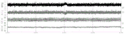
FIG. 1 is a S600 normal cut vibration map of the present invention;
FIG. 2 is a S800 normal cut vibration map of the present invention;
FIG. 3 is a S1000 normal cut vibration map of the present invention;
FIG. 4 is a main shaft side fault injection vibration map of S600 in the present invention;
FIG. 5 is a main shaft side fault injection vibration map of S800 in the present invention;
FIG. 6 is a vibration map of S1000 main shaft side fault injection in the present invention;
FIG. 7 is a S600 rail side fault injection vibration map in accordance with the present invention;
FIG. 8 is a S800 guide rail side fault injection vibration map in accordance with the present invention;
fig. 9 is a S1000 rail-side fault injection vibration map in the present invention.
Detailed Description
The technical solutions in the embodiments of the present invention will be clearly and completely described below with reference to the drawings in the embodiments of the present invention, and it is obvious that the described embodiments are only a part of the embodiments of the present invention, and not all of the embodiments. All other embodiments, which can be derived by a person skilled in the art from the embodiments given herein without making any creative effort, shall fall within the protection scope of the present invention.
Example 1
The invention provides a technical scheme that: the method for analyzing the continuous fault propagation probability of the numerical control lathe comprises a main shaft, a guide rail and a tool rest in the numerical control lathe to be analyzed, fault injection is carried out on the main shaft, the guide rail and the tool rest in normal processing, and then analysis and detection are carried out, wherein the normal processing state comprises the following steps:
1. the tool conversion process is required in the machining, namely a working task of tool changing machining is required to be included, and relevant signal information of tool rest rotation and tool position conversion in the tool changing process can be tested and acquired;
2. the method is close to the technological process in ordinary production, the shape design of the workpiece has typicality and is close to the actual production and processing, and the most common workpiece shape in the numerical control lathe processing, namely the excircle processing and cutting-off process is selected as the main experimental technological process on the premise of realizing the test purpose;
3. the shape of a processed workpiece is not required to be excessively complex, and the test deviation caused by accidental faults such as tool breakage, excessive abrasion and the like due to complex process in the test is avoided;
4. the quality of the processed workpiece is easy to ensure and easy to detect and measure, thereby being convenient for finding out the out-of-tolerance in time and realizing the correction in time;
5. the workpiece processing technology adapts to the adjustment of more parameters so as to meet the requirement of multi-parameter test comparison in the test and avoid accidental test errors caused by the processing working condition of a single technology;
the fault injection and measuring point selection of the main shaft comprise the following steps:
the method comprises the following steps: a magnetic base is connected with a magnetic meter base connecting rod, wherein the magnetic base is attracted on a machine tool body, and one end of the magnetic meter connecting rod extends into a wrench hole of the upper chuck;
step two: monitoring a radial displacement signal of the main shaft by using a non-contact displacement sensor, and indirectly reflecting the vibration condition of the main shaft by using the end face runout of the main shaft;
the fault injection and measuring point selection of the guide rail comprise the following steps:
the method comprises the following steps: fault injection is carried out by manually knocking the guide rail, and because the motion states of the guide rail and the main shaft are completely different, no danger hidden danger exists by adopting manual knocking, and the guide rail cannot be damaged by conventional knocking;
step two: according to the operation relation between the tool rest and the guide rail and the characteristics of the guide rail in the machining process, the possibility that the sensor can be fixedly installed is considered, and the selection is respectively carried out on the middle sections of the chuck and the tool rest and the middle sections of the tool rest and the tailstock.
The measuring point selection of the tool rest comprises that three vibration sensors are respectively arranged on three points, namely an upper plane measuring point of a tool rest gland, a lower plane measuring point of a cutter body, an upper plane measuring point of a tool rest base and the like.
In this embodiment, preferably, the method further includes performing normalization processing on the signal information obtained in the above to convert the signal information into the same dimension, and performing calculation analysis and evaluation.
In this embodiment, preferably, in the analysis and calculation of the adopted unification process, the theory of energy operators is introduced for the signal conversion and the analysis and calculation after the experiment.
In this embodiment, preferably, in the second step of injecting the fault of the spindle and selecting the measuring point, in order to determine the radial runout amount of the end surface of the spindle, 2 displacement sensors perpendicular to each other need to be arranged in the cross section of the spindle of the machine tool, and displacement variation amounts in the vertical direction and the horizontal direction of the spindle are simultaneously acquired to determine the real-time runout amount of the actual rotation axis in the working process, so as to reflect the working state of the spindle.
In this embodiment, preferably, in the step one of injecting the fault of the spindle and selecting the measuring point, the generated vibration is proportional to the rotation speed of the spindle, and the frequency of the knocking is 1 time of the rotation frequency of the spindle.
In this embodiment, it is preferable that the frequency response characteristics of the sensors in the spindle, the guide rail, and the tool holder are selected according to a signal during machining, wherein the characteristics of the signal include steady state, transient state, and random.
In this embodiment, the selection of each sensor in the spindle, guide, tool post preferably also includes linear range, stability, sensor accuracy, and cross-sensitivity.
Example 2
The invention provides a technical scheme that: the method for analyzing the continuous fault propagation probability of the numerical control lathe comprises a main shaft, a guide rail and a tool rest in the numerical control lathe to be analyzed, fault injection is carried out on the main shaft, the guide rail and the tool rest in normal processing, and then analysis and detection are carried out, wherein the normal processing state comprises the following steps:
1. the tool conversion process is required in the machining, namely a working task of tool changing machining is required to be included, and relevant signal information of tool rest rotation and tool position conversion in the tool changing process can be tested and acquired;
2. the method is close to the technological process in ordinary production, the shape design of the workpiece has typicality and is close to the actual production and processing, and the most common workpiece shape in the numerical control lathe processing, namely the excircle processing and cutting-off process is selected as the main experimental technological process on the premise of realizing the test purpose;
3. the shape of a processed workpiece is not required to be excessively complex, and the test deviation caused by accidental faults such as tool breakage, excessive abrasion and the like due to complex process in the test is avoided;
4. the quality of the processed workpiece is easy to ensure and easy to detect and measure, thereby being convenient for finding out the out-of-tolerance in time and realizing the correction in time;
5. the workpiece processing technology adapts to the adjustment of more parameters so as to meet the requirement of multi-parameter test comparison in the test and avoid accidental test errors caused by the processing working condition of a single technology;
the fault injection and measuring point selection of the main shaft comprise the following steps:
the method comprises the following steps: a magnetic base is connected with a magnetic meter base connecting rod, wherein the magnetic base is attracted on a machine tool body, and one end of the magnetic meter connecting rod extends into a wrench hole of the upper chuck;
step two: monitoring a radial displacement signal of the main shaft by using a non-contact displacement sensor, and indirectly reflecting the vibration condition of the main shaft by using the end face runout of the main shaft;
the fault injection and measuring point selection of the guide rail comprise the following steps:
the method comprises the following steps: fault injection is carried out by manually knocking the guide rail;
step two: according to the operation relation between the tool rest and the guide rail and the characteristics of the guide rail in the machining process, the possibility that the sensor can be fixedly installed is considered, and the selection is respectively carried out on the middle sections of the chuck and the tool rest and the middle sections of the tool rest and the tailstock.
The measuring point selection of the tool rest comprises that three vibration sensors are respectively arranged on three points, namely an upper plane measuring point of a tool rest gland, a lower plane measuring point of a cutter body, an upper plane measuring point of a tool rest base and the like.
In this embodiment, preferably, the method further includes performing normalization processing on the signal information obtained in the above to convert the signal information into the same dimension, and performing calculation analysis and evaluation.
In this embodiment, preferably, in the analysis and calculation of the adopted unification process, the theory of energy operators is introduced for the signal conversion and the analysis and calculation after the experiment.
In this embodiment, preferably, in the second step of injecting the fault of the spindle and selecting the measuring point, in order to determine the radial runout amount of the end surface of the spindle, 2 displacement sensors perpendicular to each other need to be arranged in the cross section of the spindle of the machine tool, and displacement variation amounts in the vertical direction and the horizontal direction of the spindle are simultaneously acquired to determine the real-time runout amount of the actual rotation axis in the working process, so as to reflect the working state of the spindle.
In this embodiment, preferably, in the step one of injecting the fault of the spindle and selecting the measuring point, the generated vibration is proportional to the rotation speed of the spindle, and the frequency of the knocking is 2 times of the rotation frequency of the spindle.
In this embodiment, it is preferable that the frequency response characteristics of the sensors in the spindle, the guide rail, and the tool holder are selected according to a signal during machining, wherein the characteristics of the signal include steady state, transient state, and random.
In this embodiment, the selection of each sensor in the spindle, guide, tool post preferably also includes linear range, stability, sensor accuracy, and cross-sensitivity.
Example 3
The invention provides a technical scheme that: the method for analyzing the continuous fault propagation probability of the numerical control lathe comprises a main shaft, a guide rail and a tool rest in the numerical control lathe to be analyzed, fault injection is carried out on the main shaft, the guide rail and the tool rest in normal processing, and then analysis and detection are carried out, wherein the normal processing state comprises the following steps:
1. the tool conversion process is required in the machining, namely a working task of tool changing machining is required to be included, and relevant signal information of tool rest rotation and tool position conversion in the tool changing process can be tested and acquired;
2. the method is close to the technological process in ordinary production, the shape design of the workpiece has typicality and is close to the actual production and processing, and the most common workpiece shape in the numerical control lathe processing, namely the excircle processing and cutting-off process is selected as the main experimental technological process on the premise of realizing the test purpose;
3. the shape of a processed workpiece is not required to be excessively complex, and the test deviation caused by accidental faults such as tool breakage, excessive abrasion and the like due to complex process in the test is avoided;
4. the quality of the processed workpiece is easy to ensure and easy to detect and measure, thereby being convenient for finding out the out-of-tolerance in time and realizing the correction in time;
5. the workpiece processing technology adapts to the adjustment of more parameters so as to meet the requirement of multi-parameter test comparison in the test and avoid accidental test errors caused by the processing working condition of a single technology;
the fault injection and measuring point selection of the main shaft comprise the following steps:
the method comprises the following steps: a magnetic base is connected with a magnetic meter base connecting rod, wherein the magnetic base is attracted on a machine tool body, and one end of the magnetic meter connecting rod extends into a wrench hole of the upper chuck;
step two: monitoring a radial displacement signal of the main shaft by using a non-contact displacement sensor, and indirectly reflecting the vibration condition of the main shaft by using the end face runout of the main shaft;
the fault injection and measuring point selection of the guide rail comprise the following steps:
the method comprises the following steps: fault injection is carried out by manually knocking the guide rail;
step two: according to the operation relation between the tool rest and the guide rail and the characteristics of the guide rail in the machining process, the possibility that the sensor can be fixedly installed is considered, and the selection is respectively carried out on the middle sections of the chuck and the tool rest and the middle sections of the tool rest and the tailstock.
The measuring point selection of the tool rest comprises that three vibration sensors are respectively arranged on three points, namely an upper plane measuring point of a tool rest gland, a lower plane measuring point of a cutter body, an upper plane measuring point of a tool rest base and the like.
In this embodiment, preferably, the method further includes performing normalization processing on the signal information obtained in the above to convert the signal information into the same dimension, and performing calculation analysis and evaluation.
In this embodiment, preferably, in the analysis and calculation of the adopted unification process, the theory of energy operators is introduced for the signal conversion and the analysis and calculation after the experiment.
In this embodiment, preferably, in the second step of injecting the fault of the spindle and selecting the measuring point, in order to determine the radial runout amount of the end surface of the spindle, 2 displacement sensors perpendicular to each other need to be arranged in the cross section of the spindle of the machine tool, and displacement variation amounts in the vertical direction and the horizontal direction of the spindle are simultaneously acquired to determine the real-time runout amount of the actual rotation axis in the working process, so as to reflect the working state of the spindle.
In this embodiment, preferably, in the step one of injecting the fault of the spindle and selecting the measuring point, the generated vibration is proportional to the rotation speed of the spindle, and the frequency of the knocking is 3 times of the rotation frequency of the spindle.
In this embodiment, the frequency response characteristics of the sensors in the spindle, guide, tool holder are preferably selected based on the signals during machining, wherein the characteristics of the signals include steady state and transient state.
In this embodiment, the selection of each sensor in the spindle, guide, tool post preferably also includes linear range, stability, sensor accuracy, and cross-sensitivity.
The energy operator in the invention refers to: for a given signal x (t), the Teager energy operator ψ is defined as:

in the formula:


when the vibration is simulated through spring damping, a mass with mass m and a spring with rigidity k form a linear undamped system. X (t) represents the relative displacement of a mass m, to Expressing the second derivative of the displacement x (t) with respect to time, the following equation of motion is obtained from newton's law of motion:

the solution for x (t) can be obtained by equation (3.2) describing the motion of the mass as shown in equation 3.3:

accordingly, its first and second order differentials, i.e. velocity and acceleration, are:


in the formula:
a is the vibration amplitude of the simple harmonic motion;
ω -natural frequency;

at any moment, the mechanical energy in the vibration system is composed of the kinetic energy of the mass and the potential energy stored inside the spring, that is:


the experiment carries out the fault injection test on the lathe under the three conditions of 600rpm, 800rpm and 1000rpm, the test is carried out under different working conditions, and the real-time signal maps of the main shaft, the tool rest and the guide rail during each turning are collected, as shown in fig. 1-9, the fourth channel from top to bottom is a displacement change signal in the vertical direction of the main shaft, the third channel from top to bottom is a displacement change signal in the horizontal direction of the main shaft, the first channel from top to bottom is a vibration signal of the tool rest, and the vibration signal of the guide rail is corresponding to the second channel from top to bottom.
Although embodiments of the present invention have been shown and described, it will be appreciated by those skilled in the art that changes, modifications, substitutions and alterations can be made in these embodiments without departing from the principles and spirit of the invention, the scope of which is defined in the appended claims and their equivalents.
Claims (7)
Priority Applications (1)
| Application Number | Priority Date | Filing Date | Title |
|---|---|---|---|
| CN201910599715.6A CN110370077B (en) | 2019-07-04 | 2019-07-04 | Probability Analysis Method of Continuous Fault Propagation for CNC Lathe |
Applications Claiming Priority (1)
| Application Number | Priority Date | Filing Date | Title |
|---|---|---|---|
| CN201910599715.6A CN110370077B (en) | 2019-07-04 | 2019-07-04 | Probability Analysis Method of Continuous Fault Propagation for CNC Lathe |
Publications (2)
| Publication Number | Publication Date |
|---|---|
| CN110370077A CN110370077A (en) | 2019-10-25 |
| CN110370077B true CN110370077B (en) | 2021-04-06 |
Family
ID=68251940
Family Applications (1)
| Application Number | Title | Priority Date | Filing Date |
|---|---|---|---|
| CN201910599715.6A Expired - Fee Related CN110370077B (en) | 2019-07-04 | 2019-07-04 | Probability Analysis Method of Continuous Fault Propagation for CNC Lathe |
Country Status (1)
| Country | Link |
|---|---|
| CN (1) | CN110370077B (en) |
Families Citing this family (2)
| Publication number | Priority date | Publication date | Assignee | Title |
|---|---|---|---|---|
| CN113128099B (en) * | 2021-05-08 | 2024-09-06 | 玛瑜科创服务(南京)有限公司 | Method for predicting frequency of turning workpiece |
| CN116842183B (en) * | 2022-03-22 | 2026-02-06 | 中国移动通信集团江苏有限公司 | Map merging method and device, electronic equipment and storage medium |
Family Cites Families (6)
| Publication number | Priority date | Publication date | Assignee | Title |
|---|---|---|---|---|
| JPH11268096A (en) * | 1998-12-28 | 1999-10-05 | Toyo Mach & Metal Co Ltd | Molding machine and trouble diagnosis method for molding machine |
| CN102662389A (en) * | 2012-03-21 | 2012-09-12 | 中国人民解放军国防科学技术大学 | Monitoring parameter selection method based on failure characteristic analysis |
| CN103870659B (en) * | 2014-03-28 | 2016-12-07 | 吉林大学 | A kind of fault of numerical control machine tool analyzes method |
| CN106406229B (en) * | 2016-12-20 | 2018-04-03 | 吉林大学 | A kind of diagnosing faults of numerical control machine method |
| CN106597992B (en) * | 2017-01-19 | 2019-10-08 | 吉林大学 | A kind of numerically-controlled machine tool component importance analysis |
| CN109597752B (en) * | 2018-10-19 | 2022-11-04 | 中国船舶重工集团公司第七一六研究所 | Simulation Method of Fault Propagation Path Based on Complex Network Model |
-
2019
- 2019-07-04 CN CN201910599715.6A patent/CN110370077B/en not_active Expired - Fee Related
Also Published As
| Publication number | Publication date |
|---|---|
| CN110370077A (en) | 2019-10-25 |
Similar Documents
| Publication | Publication Date | Title |
|---|---|---|
| US9186765B2 (en) | Monitoring method and monitoring apparatus for machine tool, and machine tool | |
| US20240036543A1 (en) | Tool wear monitoring method and system under variable operational conditions based on decoupling of cutting force component | |
| US5663894A (en) | System and method for machining process characterization using mechanical signature analysis | |
| Grossi et al. | Spindle speed ramp-up test: A novel experimental approach for chatter stability detection | |
| CN108445835B (en) | A Method for Part Machining Dimension Prediction of CNC Machine Tool | |
| CN102975119B (en) | Monitoring and diagnosing system of operation and process state of numerically controlled cylindrical grinding machine | |
| US20200311321A1 (en) | Method for determining real-time thermal deformation attitude of spindle | |
| CN110091216B (en) | Monitoring and correlation analysis system and method for milling noise and milling vibration | |
| Mitsui | Development of a new measuring method for spindle rotation accuracy by three points method | |
| KR102224333B1 (en) | An inspection system of spindle run-out in cnc machines and a method thereof | |
| CN116511996A (en) | Drilling process simulation and detection device and detection method | |
| CN109531270B (en) | Modal testing method of numerical control machine tool feeding system based on built-in sensor | |
| CN110370077A (en) | Numerically controlled lathe continuous fault probability of spreading analysis method | |
| Zou et al. | Online tool condition monitoring of CNC turnings based on motor current signature analysis | |
| Plapper et al. | Sensorless machine tool condition monitoring based on open NCs | |
| CN104889821B (en) | Numerically-controlled slide reliability cutting test method under simulated condition | |
| CN210731877U (en) | Comprehensive performance detection system of numerical control rotary table | |
| Wöste et al. | A systematic approach for data acquisition and analysis of spindle speed-dependent modal parameters | |
| Bauerdick et al. | An automated procedure for workpiece quality monitoring based on machine drive-based signals in machine tools | |
| Kim et al. | The development of embedded device to detect chatter vibration in machine tools and CNC-based autonomous compensation | |
| Bisu et al. | In-situ Spindle Diagnostic with Automated Fault Defects Integration | |
| Dunwoody | Automated identification of cutting force coefficients and tool dynamics on CNC machines | |
| CN112828680A (en) | Tool wear discrimination method based on cutting chatter acceleration | |
| CN107449600A (en) | A kind of online band saw Crack and fall tooth fault detection and diagnosis method and system | |
| Gil et al. | IDENTIFICATION OF THE ROOT CAUSE OF SURFACE TOPOGRAPHY INACCURACIES BY MEANS OF PROCESS MONITORING: INDUSTRIAL EXAMPLES. |
Legal Events
| Date | Code | Title | Description |
|---|---|---|---|
| PB01 | Publication | ||
| PB01 | Publication | ||
| SE01 | Entry into force of request for substantive examination | ||
| SE01 | Entry into force of request for substantive examination | ||
| GR01 | Patent grant | ||
| GR01 | Patent grant | ||
| CF01 | Termination of patent right due to non-payment of annual fee |
Granted publication date: 20210406 |
|
| CF01 | Termination of patent right due to non-payment of annual fee |