Disclosure of Invention
The invention provides an air conditioner for preventing liquid impact of a compressor and a control method for preventing liquid impact of the compressor, aiming at the problem that the air conditioner running in a low-temperature and ultralow-temperature environment in the prior art has compressor hydraulic pressure.
In order to achieve the purpose, the air conditioner for preventing the compressor from liquid impact provided by the invention adopts the following technical scheme:
an air conditioner for preventing liquid impact of a compressor, comprising:
the refrigerant circulating loop is formed by sequentially connecting at least a compressor, a reversing valve, a first heat exchanger, a throttling device, a second heat exchanger and a liquid storage tank;
the outdoor environment temperature sensor is used for detecting the outdoor environment temperature in real time;
the compressor muffler sensor is used for detecting the temperature of a refrigerant of the compressor muffler in real time;
it is characterized by also comprising:
one end of the bypass pipeline is connected to a pipeline between the reversing valve and the first heat exchanger, the other end of the bypass pipeline is connected to a pipeline between the first heat exchanger and the throttling device, and at least one part of the bypass pipeline is coiled on the liquid storage tank or is positioned at the lower part of the compressor;
and the control valve is arranged on the bypass pipeline.
At least one part of the bypass pipeline is spirally coiled on the liquid storage tank along the height direction of the liquid storage tank.
At least one part of the bypass pipeline is spirally wound into concentric circles on a horizontal plane and is positioned at the bottom of the compressor.
The invention also provides a control method for preventing the compressor liquid impact, which is applied to the air conditioner for preventing the compressor liquid impact, and comprises the following steps:
s1, powering on the air conditioner and starting up;
s2, detecting the actual outdoor environment temperature T in real time;
s3, comparing the detected actual outdoor environment temperature T with the outdoor environment temperature T set by the air conditioning system Is provided with By comparison, if T>T Is provided with The control valve is kept closed, if T is less than or equal to T Is provided with Opening the control valve;
s4, starting a compressor, and operating an air conditioner;
if the control valve is opened in step S3 and step S4 is executed, the bypass line and the first heat exchanger are connected in parallel, and a part of the high-temperature refrigerant discharged from the exhaust port of the compressor enters the bypass line to preheat the compressor.
Further comprising the steps of:
s5, if the control valve is opened and the step S4 is executed in the step S3, the compressor is opened for a certain time t 1 And then, adjusting the opening of the control valve in real time: at regular intervals of time t 2 Detecting the temperature T of the refrigerant in the return pipe of the primary compressor h Detecting the temperature T of the refrigerant in the return pipe of the compressor h And the evaporation temperature t of the refrigerant 0 Comparing, if T is less than or equal to 0 h <t 0 The opening degree of the control valve is N 1 If T is 1 ≤T h <0, opening degree of the control valve is N 2 If T is h < T 1 If T, the control valve is fully opened h T0, closing the control valve;
wherein, N is more than 0 1 <N 2 <1,t 1 > t 2 ,3min≤t 1 ≤5min,T 1 ≤-10℃。
N 1 =1/3,N 2 =2/3。
In step S5, if T is detected for the first time h <t 0 Last n consecutive times of detection of T h ≥t 0 Then, T is detected h Is extended by t 3 Until it is inspected againMeasure T h <t 0 Time recovery interval of t 2 Repeating step S5; wherein, t 3 > t 2 And n is a natural number greater than 1.
5min≤t 3 ≤10 min,5≤n≤10。
Compared with the prior art, the invention has the advantages and positive effects that:
1. at least one part of the bypass pipeline is coiled on the liquid storage tank of the compressor or arranged at the lower part of the compressor by additionally arranging the bypass pipeline, and the detected actual outdoor environment temperature T and the outdoor environment temperature T set by the air conditioning system are compared Is provided with Comparing to determine whether to open the control valve on the bypass line, and when the detected actual outdoor temperature T is too low to be lower than the outdoor temperature T Is provided with The control valve is opened to enable the bypass pipeline and the first heat exchanger to form a parallel structure, and a part of high-temperature refrigerant discharged from the exhaust port of the compressor enters the bypass pipeline to preheat the compressor, so that the liquid impact phenomenon of the compressor is effectively prevented, the compressor is prevented from being damaged, and the air-conditioning refrigeration or heating is smoothly carried out in a low-temperature or ultralow-temperature environment;
2. before the compressor is started, the refrigerant of the bypass pipeline can preheat the compressor oil which is still in a low-temperature environment, and adverse effects on the starting and the performance of the compressor caused by thickening of the compressor are avoided.
Other features and advantages of the present invention will become more apparent from the following detailed description of the invention when taken in conjunction with the accompanying drawings.
Detailed Description
In order to make the objects, technical solutions and advantages of the present invention more apparent, the present invention will be described in further detail with reference to the accompanying drawings and examples.
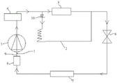
Referring to fig. 1 to 3, the air conditioner for preventing compressor liquid impact in the embodiment includes a refrigerant circulation loop, a compressor muffler sensor 1, an outdoor ambient temperature sensor (not shown) located outside the air conditioner, a bypass pipeline 2 and a control valve 10, wherein the refrigerant circulation loop is formed by sequentially connecting a compressor 3, a reversing valve 4, a first heat exchanger 5, a throttling device 6, a second heat exchanger 7 and a liquid storage tank 8, the compressor muffler sensor 1 is used for detecting the temperature of refrigerant in a compressor muffler 9 in real time, and the outdoor ambient temperature sensor is used for detecting the outdoor ambient temperature in real time; one end of the bypass pipeline 2 is connected to a pipeline between the reversing valve 4 and the first heat exchanger 5, the other end of the bypass pipeline is connected to a pipeline between the first heat exchanger 5 and the throttling device 6, at least one part of the bypass pipeline 2 is coiled on the liquid storage tank 8 or is positioned at the lower part of the compressor 3, and the control valve 10 is arranged on the bypass pipeline 2 and used for controlling the on-off of the bypass pipeline 2. The lower portion of the compressor 3, i.e., the portion near the suction port of the compressor 3, includes the lower end of the compressor 3 and the bottom of the compressor 3.
When the air conditioner is used for refrigerating, the first heat exchanger 5 is an outdoor condenser, the second heat exchanger 7 is an indoor evaporator, and when the air conditioner is used for heating, the first heat exchanger 5 is an indoor evaporator, and the second heat exchanger 7 is an outdoor condenser.
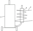
Further, as shown in fig. 2, at least a portion of the bypass pipe 2 is spirally wound around the liquid storage tank 8 along the height direction of the liquid storage tank 8, and is in full contact with the liquid storage tank 8, so as to increase the heat exchange area, transfer the heat of the high-temperature refrigerant in the bypass pipe 2 to the liquid storage tank 8 as much as possible, increase the temperature of the liquid in the liquid storage tank 8, and reduce the liquid impact phenomenon.
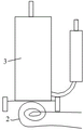
When at least a part of the bypass line 2 is located at the lower part of the compressor 3, as shown in fig. 3, it is preferable that a part of the bypass line 2 is spirally wound in a concentric circle in a horizontal plane and located at the bottom of the compressor 3, and also to increase the heat exchange area and increase the temperature of the liquid in the compressor 3 as fast as possible.
Referring to fig. 4, the present embodiment further provides a control method for preventing a compressor from liquid impact, including the following steps:
s1, powering on the air conditioner and starting up the air conditioner;
s2, detecting the actual outdoor environment temperature T in real time;
s3, comparing the detected actual outdoor environment temperature T with the outdoor environment temperature T set by the air conditioning system Is provided with By comparison, if T>T Is provided with The control valve is kept closed, if T is less than or equal to T Is provided with Opening the control valve;
s4, starting a compressor, and operating an air conditioner;
wherein, the time from the power-on of the air conditioner to the start of the compressor is 3-5min, and whether the control valve 10 is opened or not is judged in the time; when the outdoor environment temperature is-15 to-10 ℃, the phenomenon of liquid impact of the compressor is easy to occur, then T Is provided with Can be set to-10 degrees; with reference to FIG. 1, if T is less than or equal to T in step S3 Is provided with It is described that the outdoor environment is too low, the compressor 3 is located outdoors, the temperature of the compressor itself is low, the temperature of the return refrigerant is too low, the liquid refrigerant is accumulated in the compressor, and there is a risk of liquid slugging at any time, at this time, after the control valve 10 is opened and the compressor 3 is opened, the bypass pipeline 2 and the first heat exchanger 5 are connected in parallel, a part of the high-temperature refrigerant discharged from the exhaust port of the compressor 3 enters the bypass pipeline 2 to preheat the compressor 3, specifically, the liquid storage tank 8 is preheated as shown in fig. 2 to indirectly preheat the compressor 3, or the compressor 3 is directly preheated as shown in fig. 3.
If T is>T Is provided with If the outdoor environment temperature is at the level where the compressor liquid impact phenomenon is not easy to occur, the control is carried outThe valve 10 is kept closed, and the compressor 3 is started normally.
In order to more precisely control the flow rate of the refrigerant entering the bypass line 2 and effectively prevent liquid slugging, the control method of the present embodiment further includes step S5, i.e. if the opening condition of the control valve 10 is satisfied in step S3, the control valve is opened, then step S4 is executed, the compressor 3 is opened, the air conditioner is operated, and when the compressor 3 is opened for a certain time t 1 Then, the opening degree of the control valve 10 should be adjusted in real time. In particular, with reference to fig. 5, at regular intervals t 2 Detecting the refrigerant temperature T of the return air pipe 9 of the primary compressor h Detecting T h And the evaporation temperature t of the refrigerant 0 Comparing, if T is less than or equal to 0 h <t 0 The opening of the control valve 10 is N 1 If T is 1 ≤T h <0, the opening degree of the control valve 10 is N 2 If T is h < T 1 Control valve 10 is fully open, if T h T0, the control valve 10 is closed; wherein, 0 < N 1 <N 2 <1,t 1 > t 2 Since the compressor 3 is started for 3-5min and then operates steadily, t 1 The value is preferably t which is less than or equal to 3min 1 ≤5min;T 1 For a reference parameter, similarly, since the outdoor environment temperature is between-15 ℃ and-10 ℃, the liquid impact phenomenon of the compressor is easy to occur, and in order to prevent the liquid impact of the compressor, the lower the temperature is, the larger the opening degree of the control valve 10 is, and the T is 1 Preferably not more than-10 ℃.
Here, it is based on the refrigerant temperature T of the compressor return pipe 9 h The opening of the control valve 10 is controlled because the liquid impact of the compressor is mainly caused by the low temperature of the return refrigerant, and the temperature T of the refrigerant in the return pipe 9 of the compressor h The reflected temperature is the actual return refrigerant temperature, so that after the compressor 3 is started, the temperature is determined according to the refrigerant temperature T of the compressor muffler 9 h The opening degree of the control valve 10 is adjusted, so that the opening degree can be controlled more accurately, the flow of the refrigerant entering the bypass coil 2 is controlled accurately, and the liquid impact condition of the compressor is effectively prevented.
In this example N 1 =1/3,N 2 =2/3, of course, the control valve can be set according to specific working conditions10 opening degree.
Further, in step S5, if T is detected for the first time h <t 0 Then, T is detected n times in succession h ≥t 0 That is, the temperature of the return refrigerant is high, the risk of liquid impact is low, and the detection of T is convenient for energy conservation and frequent detection is avoided h May be extended by t 3 I.e. every time t 3 Detecting the refrigerant temperature T of the return air pipe 9 of the primary compressor h Detecting T h And the evaporation temperature t of the refrigerant 0 Making comparison until T is detected again h <t 0 Time, recovery time interval is t 2 I.e. resume every time t 2 Detecting the refrigerant temperature T of the return air pipe 9 of the primary compressor h And repeating step S5; e.g. resume every time t 2 Detecting the refrigerant temperature T of the return air pipe 9 of the primary compressor h Then, the detected T is detected h And the evaporation temperature t of the refrigerant 0 Comparing, if T is less than or equal to 0 h <t 0 The opening degree of the control valve 10 is N 1 If T is 1 ≤T h <0, the opening degree of the control valve 10 is N 2 If T is h < T 1 Control valve 10 is fully open, if T h T0, the control valve 10 closes. If T is detected for the first time h <t 0 Thereafter, T is detected n consecutive times h ≥t 0 Will detect T h Is again extended by t 3 Until T is detected again h <t 0 When the time is again recovered for a time interval of t 2 And so on.
Wherein, t 3 > t 2 And n is a natural number greater than 1.
Further, t is more than or equal to 5min 3 N is less than or equal to 5 and less than or equal to 10 min, such as t 3 Is 5min, t 2 For 1min, n = 5.
The above examples are only intended to illustrate the technical solution of the present invention, but not to limit it; although the present invention has been described in detail with reference to the foregoing embodiments, it will be apparent to those skilled in the art that various changes may be made and equivalents may be substituted for elements thereof; such modifications and substitutions do not depart from the spirit and scope of the corresponding claims.