CN110519528B - A panoramic video synthesis method, device and electronic device - Google Patents
A panoramic video synthesis method, device and electronic device Download PDFInfo
- Publication number
- CN110519528B CN110519528B CN201810496114.8A CN201810496114A CN110519528B CN 110519528 B CN110519528 B CN 110519528B CN 201810496114 A CN201810496114 A CN 201810496114A CN 110519528 B CN110519528 B CN 110519528B
- Authority
- CN
- China
- Prior art keywords
- preset
- fisheye
- image
- pixel point
- calibration
- Prior art date
- Legal status (The legal status is an assumption and is not a legal conclusion. Google has not performed a legal analysis and makes no representation as to the accuracy of the status listed.)
- Active
Links
Images


Classifications
-
- H—ELECTRICITY
- H04—ELECTRIC COMMUNICATION TECHNIQUE
- H04N—PICTORIAL COMMUNICATION, e.g. TELEVISION
- H04N23/00—Cameras or camera modules comprising electronic image sensors; Control thereof
- H04N23/60—Control of cameras or camera modules
- H04N23/67—Focus control based on electronic image sensor signals
-
- H—ELECTRICITY
- H04—ELECTRIC COMMUNICATION TECHNIQUE
- H04N—PICTORIAL COMMUNICATION, e.g. TELEVISION
- H04N23/00—Cameras or camera modules comprising electronic image sensors; Control thereof
- H04N23/60—Control of cameras or camera modules
- H04N23/698—Control of cameras or camera modules for achieving an enlarged field of view, e.g. panoramic image capture
-
- H—ELECTRICITY
- H04—ELECTRIC COMMUNICATION TECHNIQUE
- H04N—PICTORIAL COMMUNICATION, e.g. TELEVISION
- H04N23/00—Cameras or camera modules comprising electronic image sensors; Control thereof
- H04N23/80—Camera processing pipelines; Components thereof
-
- H—ELECTRICITY
- H04—ELECTRIC COMMUNICATION TECHNIQUE
- H04N—PICTORIAL COMMUNICATION, e.g. TELEVISION
- H04N5/00—Details of television systems
- H04N5/222—Studio circuitry; Studio devices; Studio equipment
- H04N5/262—Studio circuits, e.g. for mixing, switching-over, change of character of image, other special effects ; Cameras specially adapted for the electronic generation of special effects
Landscapes
- Engineering & Computer Science (AREA)
- Multimedia (AREA)
- Signal Processing (AREA)
- Studio Devices (AREA)
- Image Processing (AREA)
Abstract
The embodiment of the invention provides a panoramic video synthesis method, a panoramic video synthesis device and electronic equipment, wherein the panoramic video synthesis method comprises the following steps: acquiring original videos respectively shot by two fisheye cameras in the double-fisheye equipment; the method comprises the steps that a pre-established panoramic synthesis mapping table is searched, videos to be spliced corresponding to original videos and splicing relations among the videos to be spliced are generated aiming at the original videos, and the panoramic synthesis mapping table is obtained by processing all calibration images respectively on the basis of external parameters of fisheye cameras calibrated in calibration images acquired by all fisheye cameras, internal parameters of all fisheye cameras calibrated in a pre-established specified calibration field by using a preset upright friend calibration method and field angles of the calibration images acquired by all fisheye cameras; and splicing the videos to be spliced according to the splicing relation to synthesize the panoramic video. Through the scheme, splicing errors can be avoided when the video shot by the fisheye equipment is spliced.
Description
Technical Field
The present invention relates to the field of image processing technologies, and in particular, to a panoramic video synthesis method, a panoramic video synthesis apparatus, and an electronic device.
Background
The fisheye camera is an ultra-wide angle camera for simulating the effect of looking up on the water surface of fishes, and the field angle of the fisheye camera is larger than or equal to 180 degrees. The fisheye camera has the advantages of large field angle, multiple accommodated scenes, adaptability to narrow space shooting and the like, and is widely applied to the fields of virtual and real scene technology, robot navigation, visual monitoring, intelligent auxiliary driving and the like.
Because the field angle of the fisheye cameras is larger than or equal to 180 degrees, the two fisheye cameras are arranged back to form a double-fisheye device, so that fisheye images shot by the two fisheye cameras are spliced to obtain a 360-degree panoramic image. However, since the fisheye image photographed by the fisheye camera has an extremely wide viewing angle, the curvature distortion of the photographed fisheye image is very large. Therefore, when the fisheye images captured by the two fisheye cameras are to be stitched, distortion correction processing is required.
In the corresponding panoramic image synthesis method, a fisheye image shot by a fisheye camera is scanned by a seed growing method, an effective circular area of the fisheye image is determined, the principal point coordinate and the focal length of the fisheye image are detected in the effective circular area, spherical projection is carried out by using the principal point coordinate and the focal length to obtain a spherical projection image, and then image registration and splicing are carried out on the spherical projection image by a characteristic matching method to obtain the panoramic image.
However, since the effective area of the fisheye image is not completely circular, or the effective circular area may be cut, and the effective circular area cannot be obtained, the principal point coordinates of the fisheye image may shift or the focal length may change, which may affect the accuracy of spherical projection, resulting in a splicing error such as misalignment or ghost when the fisheye image is spliced.
Disclosure of Invention
The embodiment of the invention aims to provide a panoramic video synthesis method, a panoramic video synthesis device and electronic equipment, so as to avoid splicing errors when videos shot by fisheye equipment are spliced. The specific technical scheme is as follows:
in a first aspect, an embodiment of the present invention provides a panoramic video synthesis method, where the method includes:
acquiring original videos respectively shot by two fisheye cameras in the double-fisheye equipment;
respectively generating videos to be spliced corresponding to the original videos and a splicing relation among the videos to be spliced aiming at the original videos by searching a pre-established panoramic synthesis mapping table, wherein the panoramic synthesis mapping table is obtained by respectively processing all calibration images based on external parameters of fisheye cameras calibrated in calibration images acquired by all fisheye cameras, internal parameters of all fisheye cameras calibrated in a pre-established specified calibration field by using a preset Zhang-up friend calibration method and field angles of the calibration images acquired by all fisheye cameras;
and splicing the videos to be spliced according to the splicing relation to synthesize the panoramic video.
Optionally, the method for establishing the panorama synthesis mapping table includes:
acquiring calibration images respectively acquired by the two fisheye cameras, external parameters of the fisheye cameras calibrated in the calibration images and the field angles of the calibration images;
obtaining internal parameters of each fisheye camera by using a preset Zhang Zhengyou calibration method in a preset specified calibration field;
according to the internal parameters of each fisheye camera and the field angle of the calibration image collected by each fisheye camera, performing spherical projection expansion on each calibration image respectively to generate a spherical expansion image corresponding to the calibration image;
obtaining the relative position relation between the spherical expansion images according to the external parameters of the fisheye cameras;
and processing each spherical expansion image according to the relative position relationship to obtain a panoramic synthesis mapping table.
Optionally, the method for establishing the panorama synthesis mapping table includes:
acquiring calibration images respectively acquired by the two fisheye cameras, external parameters of the fisheye cameras calibrated in the calibration images and the field angles of the calibration images;
obtaining internal parameters of each fisheye camera by using a preset Zhang Zhengyou calibration method in a preset specified calibration field;
establishing a first panoramic mapping table, wherein the content of the first panoramic mapping table is empty;
obtaining the relative position relation between preset areas in the first panorama mapping table according to the external parameters of the fisheye cameras;
according to the relative position relation, carrying out inverse transformation on each preset area to obtain an inverse transformation area of the preset area;
according to the internal parameters of each fisheye camera and the field angle of the calibration image collected by each fisheye camera, performing spherical projection expansion on each calibration image respectively to generate a spherical expansion image corresponding to the calibration image;
and determining a panoramic synthesis mapping table according to the corresponding relation between each spherical expansion image and each inverse transformation area.
Optionally, the internal reference of the fisheye camera includes: the principal point coordinate and the focal length of the fisheye camera;
the generating of the spherical expansion image corresponding to the calibration image by respectively performing spherical projection expansion on each calibration image according to the internal reference of each fisheye camera and the angle of view of the calibration image acquired by each fisheye camera comprises:
acquiring coordinates of a first pixel point on a target spherical expansion image, and a preset width and a preset height of the target spherical expansion image, wherein the first pixel point is any pixel point on the target spherical expansion image;
obtaining the polar coordinate of the first pixel point through a preset polar coordinate conversion relation according to the focal length of the fisheye camera, the first pixel point coordinate, the preset width and the preset height;
according to the polar coordinates of the first pixel points, obtaining second pixel point coordinates which map the first pixel points to the preset unit spherical surface through a first preset mapping relation between the polar coordinates and pixel point coordinates on the preset unit spherical surface;
according to the second pixel point coordinate, the main point coordinate of the fisheye camera, the focal length of the fisheye camera and the field angle of the calibration image acquired by the fisheye camera, a third pixel point coordinate which has a mapping relation with the first pixel point on the calibration image is obtained through a second preset mapping relation of the pixel point coordinate on the preset unit spherical surface and the pixel point coordinate on the calibration image;
and according to the calculated mapping relation between each pixel point on the target spherical expansion image and each pixel point on the calibration image, taking the target spherical expansion image obtained by mapping as the spherical expansion image of the calibration image.
Optionally, the preset polar coordinate transformation relationship is as follows:

wherein, (x, y) is the first pixel point coordinate on the target spherical expansion image, (f)x,fy) Is the focal length of the fisheye camera, fxIs the horizontal focal length of the fisheye camera, fyIs the vertical focal length of the fisheye camera, the W is the preset width of the target spherical expansion image, the H is the preset height of the target spherical expansion image, the polar coordinates of the first pixel point are obtained;
the first preset mapping relationship is as follows:
Z=sin(θ)
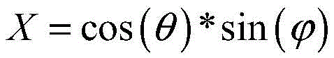
wherein, (X, Y, Z) is the second pixel point coordinate which maps the first pixel point to the preset unit spherical surface;
the second preset mapping relationship is as follows:
α=atan2(Z,X)

u=Cx+Rx*cos(α)
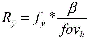
v=Cy+Ry*sin(α)
wherein α is an included angle between a first connection line and a horizontal axis in a coordinate axis in which the preset unit spherical surface is located, the first connection line is a connection line between the second pixel point and a spherical center of the preset unit spherical surface, β is an included angle between the first connection line and a longitudinal axis in the coordinate axis in which the preset unit spherical surface is located, and fovwThe field angle of the width direction of the calibration image collected by the fisheye camera, fovhThe angle of view in the height direction of the calibration image collected for the fisheye camera, RxIs the horizontal distance from the second pixel point to the center of the sphere, Ry(ii) the vertical distance from the second pixel point to the center of the sphere, (C)x,Cy) And (u, v) is the coordinate of a third pixel point which has a mapping relation with the first pixel point on the calibration image.
Optionally, the panoramic synthesis mapping table includes respective mapping tables of the two fisheye cameras, and an overlapping area with the same content exists between the mapping tables of the two fisheye cameras.
Optionally, the searching a pre-established panorama synthesis mapping table to generate, for each original video, a to-be-spliced video corresponding to the original video and a splicing relationship between the to-be-spliced videos, respectively includes:
generating video frames to be spliced corresponding to the video frames and a splicing relation between the video frames to be spliced by searching a pre-established panoramic synthesis mapping table aiming at each video frame in each original video;
generating a video to be spliced by aiming at each video frame to be spliced generated by the same original video through a preset video generation technology;
according to the splicing relation, splicing the videos to be spliced to synthesize a panoramic video, comprising the following steps:
according to the splicing relation among the video frames to be spliced, respectively splicing the corresponding video frames to be spliced in the videos to be spliced to obtain a plurality of spliced images;
respectively carrying out three-dimensional projection on each spliced image according to a preset three-dimensional projection strategy to obtain a three-dimensional panoramic image corresponding to the spliced image;
and generating a panoramic video by a preset video generation technology based on each three-dimensional panoramic image.
Optionally, the splicing the videos to be spliced according to the splicing relationship to synthesize a panoramic video includes:
according to the splicing relation, splicing the videos to be spliced to generate a two-dimensional video;
and performing three-dimensional projection on the two-dimensional video according to a preset three-dimensional projection strategy to obtain a panoramic video.
In a second aspect, an embodiment of the present invention provides a panoramic video synthesis apparatus, where the apparatus includes:
the acquisition module is used for acquiring original videos respectively shot by two fisheye cameras in the double-fisheye equipment;
the system comprises a searching module, a judging module and a display module, wherein the searching module is used for respectively generating videos to be spliced corresponding to original videos and splicing relations among the videos to be spliced by the original videos aiming at the original videos by searching a pre-established panoramic synthesis mapping table, and the panoramic synthesis mapping table is obtained by respectively processing each calibration image based on external parameters of a fisheye camera calibrated in a calibration image acquired by each fisheye camera, internal parameters of each fisheye camera calibrated by a preset Zhang Zhengyou calibration method in a pre-established specified calibration field and a field angle of the calibration image acquired by each fisheye camera;
and the splicing module is used for splicing the videos to be spliced according to the splicing relation to synthesize the panoramic video.
Optionally, the obtaining module is further configured to:
acquiring calibration images respectively acquired by the two fisheye cameras, external parameters of the fisheye cameras calibrated in the calibration images and the field angles of the calibration images;
obtaining internal parameters of each fisheye camera by using a preset Zhang Zhengyou calibration method in a preset specified calibration field;
the device further comprises:
the projection expansion module is used for respectively performing spherical projection expansion on each calibration image according to the internal reference of each fisheye camera and the field angle of the calibration image acquired by each fisheye camera to generate a spherical expansion image corresponding to the calibration image;
the acquisition module is used for acquiring the relative position relation between the spherical expansion images according to the external parameters of the fisheye cameras;
and the processing module is used for processing each spherical expansion image according to the relative position relation to obtain a panoramic synthesis mapping table.
Optionally, the obtaining module is further configured to:
acquiring calibration images respectively acquired by the two fisheye cameras, external parameters of the fisheye cameras calibrated in the calibration images and the field angles of the calibration images;
obtaining internal parameters of each fisheye camera by using a preset Zhang Zhengyou calibration method in a preset specified calibration field;
the device further comprises:
the device comprises an establishing module, a judging module and a judging module, wherein the establishing module is used for establishing a first panorama mapping table, and the content of the first panorama mapping table is empty;
the obtaining module is used for obtaining the relative position relation between preset areas in the first panorama mapping table according to the external parameters of the fisheye cameras;
the inverse transformation module is used for carrying out inverse transformation on each preset region according to the relative position relation to obtain an inverse transformation region of the preset region;
the projection expansion module is used for respectively performing spherical projection expansion on each calibration image according to the internal reference of each fisheye camera and the field angle of the calibration image acquired by each fisheye camera to generate a spherical expansion image corresponding to the calibration image;
and the determining module is used for determining the panoramic synthesis mapping table according to the corresponding relation between each spherical expansion image and each inverse transformation area.
Optionally, the internal reference of the fisheye camera includes: the principal point coordinate and the focal length of the fisheye camera;
the projection expansion module is specifically configured to:
acquiring coordinates of a first pixel point on a target spherical expansion image, and a preset width and a preset height of the target spherical expansion image, wherein the first pixel point is any pixel point on the target spherical expansion image;
obtaining the polar coordinate of the first pixel point through a preset polar coordinate conversion relation according to the focal length of the fisheye camera, the first pixel point coordinate, the preset width and the preset height;
according to the polar coordinates of the first pixel points, obtaining second pixel point coordinates which map the first pixel points to the preset unit spherical surface through a first preset mapping relation between the polar coordinates and pixel point coordinates on the preset unit spherical surface;
according to the second pixel point coordinate, the main point coordinate of the fisheye camera, the focal length of the fisheye camera and the field angle of the calibration image acquired by the fisheye camera, a third pixel point coordinate which has a mapping relation with the first pixel point on the calibration image is obtained through a second preset mapping relation of the pixel point coordinate on the preset unit spherical surface and the pixel point coordinate on the calibration image;
and according to the calculated mapping relation between each pixel point on the target spherical expansion image and each pixel point on the calibration image, taking the target spherical expansion image obtained by mapping as the spherical expansion image of the calibration image.
Optionally, the preset polar coordinate transformation relationship is as follows:


wherein, (x, y) is the first pixel point coordinate on the target spherical expansion image, (f)x,fy) Is the focal length of the fisheye camera, fxIs the horizontal focal length of the fisheye camera, fyIs the vertical focal length of the fisheye camera, the W is the preset width of the target spherical expansion image, the H is the preset height of the target spherical expansion image, the polar coordinates of the first pixel point are obtained;
the first preset mapping relationship is as follows:

Z=sin(θ)
wherein, (X, Y, Z) is the second pixel point coordinate which maps the first pixel point to the preset unit spherical surface;
the second preset mapping relationship is as follows:
α=atan2(Z,X)


u=Cx+Rx*cos(α)
v=Cy+Ry*sin(α)
wherein α is an included angle between a first connection line and a horizontal axis in a coordinate axis in which the preset unit spherical surface is located, the first connection line is a connection line between the second pixel point and a spherical center of the preset unit spherical surface, β is an included angle between the first connection line and a longitudinal axis in the coordinate axis in which the preset unit spherical surface is located, and fovwThe field angle of the width direction of the calibration image collected by the fisheye camera, fovhThe angle of view in the height direction of the calibration image collected for the fisheye camera, RxIs the horizontal distance from the second pixel point to the center of the sphere, Ry(ii) the vertical distance from the second pixel point to the center of the sphere, (C)x,Cy) And (u, v) is the coordinate of a third pixel point which has a mapping relation with the first pixel point on the calibration image.
Optionally, the panoramic synthesis mapping table includes respective mapping tables of the two fisheye cameras, and an overlapping area with the same content exists between the mapping tables of the two fisheye cameras.
Optionally, the search module is specifically configured to:
generating video frames to be spliced corresponding to the video frames and a splicing relation between the video frames to be spliced by searching a pre-established panoramic synthesis mapping table aiming at each video frame in each original video;
generating a video to be spliced by aiming at each video frame to be spliced generated by the same original video through a preset video generation technology;
the splicing module is specifically configured to:
according to the splicing relation among the video frames to be spliced, respectively splicing the corresponding video frames to be spliced in the videos to be spliced to obtain a plurality of spliced images;
respectively carrying out three-dimensional projection on each spliced image according to a preset three-dimensional projection strategy to obtain a three-dimensional panoramic image corresponding to the spliced image;
and generating a panoramic video by a preset video generation technology based on each three-dimensional panoramic image.
Optionally, the splicing module is specifically configured to:
according to the splicing relation, splicing the videos to be spliced to generate a two-dimensional video;
and performing three-dimensional projection on the two-dimensional video according to a preset three-dimensional projection strategy to obtain a panoramic video.
In a third aspect, an embodiment of the present invention provides an electronic device, including a processor and a memory, wherein,
the memory is used for storing a computer program;
the processor is configured to implement any of the method steps of the first aspect of the embodiments of the present invention when executing the program stored in the memory.
In a fourth aspect, the present invention provides a computer-readable storage medium, in which a computer program is stored, and the computer program, when executed by a processor, implements any one of the method steps described in the first aspect of the present invention.
According to the panoramic video synthesis method, the panoramic video synthesis device and the electronic equipment, the original videos shot by two fisheye cameras in the double fisheye equipment respectively are obtained; respectively generating videos to be spliced corresponding to the original videos and a splicing relation among the videos to be spliced by searching a pre-established panoramic synthesis mapping table aiming at each original video; and splicing the videos to be spliced according to the splicing relation to synthesize the panoramic video. The panoramic synthesis mapping table is obtained by respectively processing each calibration image based on the external parameters of the fisheye cameras calibrated in the calibration images acquired by each fisheye camera, the internal parameters of each fisheye camera calibrated by a preset Zhang Zhengyou calibration method in a preset specified calibration field and the angle of view of the calibration images acquired by each fisheye camera; when the panoramic video is synthesized, video splicing can be completed according to the panoramic synthesis mapping table; the external parameters, the internal parameters and the field angles of all the fisheye cameras are used as fixed parameters of all the fisheye cameras, and the main point offset, the focal length change and the like of the cameras can be reflected uniquely, so that no matter the video shot by the fisheye equipment is cut or is not in a standard circle shape, the panoramic video can be synthesized according to the table look-up operation of the panoramic synthesis mapping table, and the splicing errors caused when the shot video is cut or is not in the standard circle shape are effectively avoided.
Drawings
In order to more clearly illustrate the embodiments of the present invention or the technical solutions in the prior art, the drawings used in the description of the embodiments or the prior art will be briefly described below, it is obvious that the drawings in the following description are only some embodiments of the present invention, and for those skilled in the art, other drawings can be obtained according to the drawings without creative efforts.
Fig. 1 is a schematic flowchart of a panoramic video synthesis method according to an embodiment of the present invention;
FIG. 2a is a prior art non-clipped, non-offset fisheye image;
FIG. 2b is a prior art fisheye image without cropping and offset;
FIG. 2c is a prior art fisheye image with cropping and no offset;
FIG. 2d is a prior art clipped offset fisheye image;
fig. 3 is a flowchart illustrating a panoramic synthesis mapping table generation process according to an embodiment of the present invention;
FIG. 4 is a diagram illustrating a structure of a panorama synthesis mapping table according to an embodiment of the present invention;
fig. 5 is a flowchart illustrating a panoramic video generation process according to an embodiment of the present invention;
fig. 6 is a schematic structural diagram of a panoramic video synthesis apparatus according to an embodiment of the present invention;
fig. 7 is a schematic structural diagram of an electronic device according to an embodiment of the present invention.
Detailed Description
The technical solutions in the embodiments of the present invention will be clearly and completely described below with reference to the drawings in the embodiments of the present invention, and it is obvious that the described embodiments are only a part of the embodiments of the present invention, and not all of the embodiments. All other embodiments, which can be derived by a person skilled in the art from the embodiments given herein without making any creative effort, shall fall within the protection scope of the present invention.
In order to avoid splicing errors when videos shot by fisheye equipment are spliced, the embodiment of the invention provides a panoramic video synthesis method and device and electronic equipment.
First, a panoramic video synthesis method provided by an embodiment of the present invention is described below.
The execution main body of the panoramic video synthesis method provided by the embodiment of the invention can be a double-fisheye device comprising a core processing chip, and can also be an electronic device with a video processing synthesis function. As shown in fig. 1, a panoramic video synthesis method provided by the embodiment of the present invention may include the following steps:
s101, acquiring original videos respectively shot by two fisheye cameras in the double-fisheye equipment.
The two-fisheye device comprises two fisheye cameras, the field angle of each fisheye camera is greater than or equal to 180 degrees, and therefore the total field angle of the two-fisheye device is greater than or equal to 360 degrees. The double fisheye device may or may not include a core processing chip. If the double-fisheye device comprises the core processing chip, the core processing chip in the double-fisheye device can acquire the original video respectively shot by each fisheye camera; if the double-fisheye device does not comprise a core processing chip, the electronic device with the video processing integration function is required to acquire the original videos respectively shot by all fisheye cameras in the double-fisheye device.
The two double-fisheye cameras may not have consistent key parameters and installation parameters, wherein the key parameters include, but are not limited to, camera internal parameters, field angle, distortion, focal length, and the like; the installation parameters include, but are not limited to, installation location, installation angle, etc. The total field angle of the double-fisheye device is greater than or equal to 360 degrees.
And S102, respectively generating videos to be spliced corresponding to the original videos and splicing relations among the videos to be spliced aiming at the original videos by searching a pre-established panoramic synthesis mapping table, wherein the panoramic synthesis mapping table is obtained by respectively processing all the calibrated images based on external parameters of fisheye cameras calibrated in calibrated images acquired by all the fisheye cameras, internal parameters of all the fisheye cameras calibrated in a pre-established specified calibration field by using a preset Zhang-Zhengyou calibration method and view angles of the calibrated images acquired by all the fisheye cameras.
A panorama synthesis mapping table is previously established and stored in the execution body, and the panorama synthesis mapping table is used for synthesizing the panoramic video. The pre-established designated calibration site is as follows: the area range of the calibration site is larger than 3m by 3 m; in the calibration field, the illumination is balanced and no other interferents exist.
In the conventional panoramic image synthesis method, it is assumed that a fisheye image collected by a fisheye device has a circular effective area, as shown in fig. 2a, for each fisheye image collected by the fisheye device, half of the width and height of the fisheye image are the horizontal and vertical focal lengths of the fisheye image, that is, as shown in formula (1):

wherein R isxHorizontal focal length, R, of fisheye image collected for fisheye camerayThe fish-eye image acquisition system has the advantages that the vertical direction focal distance of the fish-eye image acquired by the fish-eye camera is adopted, the width is the width of the fish-eye image acquired by the fish-eye camera, and the height is the height of the fish-eye image acquired by the fish-eye camera.
The projection radius can be found as shown in equation (2):

wherein, R is the effective area radius of the fisheye image collected by the fisheye camera.
In the conventional panoramic image synthesis method, the center of the effective area of the fisheye image is used as the projection center to perform projection expansion of the fisheye image, so that the point (x, y) and the polar coordinates on the spherical expansion image The conversion relationship between them is as follows:

wherein pi is the circumferential ratio, theta ranges from (-pi, pi), in the range of (-pi/2, pi/2).
Polar coordinates The mapping relationship with the point (X, Y, Z) on the unit sphere is as follows:

because the center of the effective area of the fisheye image is used as the projection center, the mapping relation between the point on the unit spherical surface and the fisheye image is as follows:
α=atan2(Z,X)


u=width/2+R*cos(α)
v=height/2+R*sin(α)
wherein alpha is an included angle between the continuity of the point and the center of sphere on the unit spherical surface and the horizontal axis in the coordinate axis where the unit spherical surface is located, beta is an included angle between the continuity of the point and the center of sphere on the unit spherical surface and the vertical axis in the coordinate axis where the unit spherical surface is located, fov is a viewing angle of the fisheye image, and R isxIs the horizontal distance, R, of a point on the fisheye image from the center of the fisheye imageyThe vertical distance from a point on the fisheye image to the center of the fisheye image, and (u, v) are coordinates of a pixel point on the fisheye image.
Thereby establishing the mapping relation between the spherical expansion image and the fisheye image.
Fisheye cameras suffer from two general problems, namely fisheye images being cropped and principal point shifting. As shown in fig. 2b, when the principal point of the fisheye image is shifted, the principal point of the fisheye image is no longer the center of the effective area of the fisheye image, and the focal length of the fisheye image cannot be calculated by the above conventional method; as shown in fig. 2c, when the fisheye image is cut, the fisheye image effective area is no longer a complete circle, and the circle detection by the conventional method is invalid, so that the accurate radius of the fisheye image effective area cannot be obtained. As shown in fig. 2d, there is also a case where a fisheye image is both clipped and subject point shift occurs, and in this case, it is more impossible to acquire an accurate effective area radius and focal length.
In order to solve the problems, in the embodiment of the invention, the internal parameters of the fisheye camera are used for carrying out spherical projection expansion, so that the precision is higher and the adaptability is better. Correspondingly, the panoramic synthesis mapping table is established by performing spherical projection expansion on the calibration image acquired by the fisheye camera, so that when the original video is acquired, the original video can be spliced by directly using the panoramic synthesis mapping table, and the video splicing efficiency is improved.
Optionally, the creating manner of the panorama synthesis mapping table may include the following steps:
the method comprises the steps of firstly, obtaining calibration images respectively collected by two fisheye cameras, external parameters of the fisheye cameras calibrated in the calibration images and the field angles of the calibration images;
secondly, obtaining internal parameters of each fisheye camera by using a preset Zhangyingyou calibration method in a preset specified calibration field;
thirdly, respectively performing spherical projection expansion on each calibration image according to the internal reference of each fisheye camera and the field angle of the calibration image acquired by each fisheye camera to generate a spherical expansion image corresponding to the calibration image;
fourthly, obtaining the relative position relation between the spherical expansion images according to the external parameters of the fisheye cameras;
and fifthly, processing the spherical expansion images according to the relative position relationship to obtain a panoramic synthesis mapping table.
As shown in fig. 3, a generation process of a panorama synthesis mapping table is provided. Projecting and expanding calibration images respectively acquired by two fisheye cameras through spherical projection expansion to generate corresponding spherical expansion images, wherein the spherical expansion images are distortion-free images, then obtaining a relative position relation between the two spherical expansion images according to external parameters of the fisheye cameras, and processing the two spherical expansion images according to the relative position relation to obtain a panoramic synthesis mapping table, wherein the processing of the spherical expansion images can comprise transforming and cutting the two spherical expansion images; transforming the two spherical unwrapped images may be: and taking one of the spherical expansion images as a reference, and transforming the other spherical expansion image so as to achieve the purpose of panoramic seamless splicing.
Because the relative position relationship of the two fisheye cameras in the double fisheye equipment is fixed, the internal reference, the external reference and the angle of view of the two fisheye cameras are also fixed, therefore, in this embodiment, the internal reference, the external reference, and the angle of view of the fisheye camera can all be calibrated in advance, the external reference of the fisheye camera and the angle of view of the calibration image can be determined when the calibration image is acquired, the internal parameters of the fisheye cameras are calibrated in a preset specified calibration field by using a preset Zhang Zhengyou calibration method, the internal parameters and the external parameters of each fisheye camera can be calibrated off-line, the internal reference and the external reference of the fisheye camera are basically not changed after the calibration, and by adopting the off-line calibration mode, the method has the advantages that one pair of fisheye equipment is calibrated only once, and the panoramic video is synthesized in a table look-up mode, so that the calculation overhead can be effectively saved. The preset Zhangyingyou calibration method is a traditional method for calibrating internal reference of the camera, and is not described in detail herein.
The process of establishing the panoramic synthesis mapping table can also be established according to an inverse process, namely, an empty panoramic mapping table is established, and the corresponding relation between the full set mapping table and the calibration image is established through inverse transformation and quasi-projection expansion.
Optionally, the establishing method of the panorama synthesis mapping table may include the following steps:
the method comprises the steps of firstly, obtaining calibration images respectively collected by two fisheye cameras, external parameters of the fisheye cameras calibrated in the calibration images and the field angles of the calibration images;
secondly, obtaining internal parameters of each fisheye camera by using a preset Zhangyingyou calibration method in a preset specified calibration field;
step three, establishing a first panorama mapping table, wherein the content of the first panorama mapping table is empty;
fourthly, obtaining the relative position relation between preset areas in the first panorama mapping table according to the external parameters of the fisheye cameras;
fifthly, performing inverse transformation on each preset area according to the relative position relation to obtain an inverse transformation area of the preset area;
sixthly, respectively performing spherical projection expansion on each calibration image according to the internal reference of each fisheye camera and the field angle of the calibration image acquired by each fisheye camera to generate a spherical expansion image corresponding to the calibration image;
and seventhly, determining a panoramic synthesis mapping table according to the corresponding relation between each spherical expansion image and each inverse transformation area.
By the aid of the positive process or the reverse process, the panoramic synthesis mapping table can be established, and in comparison, the time for establishing the panoramic synthesis mapping table in the positive process is shorter, and the accuracy for establishing the panoramic synthesis mapping table in the reverse process is higher.
The calibration image is an image which is acquired by each fisheye camera in the double-fisheye equipment in advance based on respective external reference when the panoramic synthesis mapping table is established, and the calibration image can be a picture which is shot in advance, or any video frame or a plurality of video frames in a video sample which is acquired in advance based on respective external reference of each fisheye camera; of course, the calibration image may be any video frame or a plurality of video frames extracted from the original video before the original video collected by each fisheye camera is subjected to panoramic video generation. The external parameters of the fisheye cameras are calibrated in the calibration images in advance, so that the calibrated external parameters of the fisheye cameras can be directly acquired through the calibration images; and based on the calibration image, the field angle of the calibration image can be directly obtained.
Optionally, the panoramic synthesis mapping table includes respective mapping tables of two fisheye cameras, and an overlapping area with the same content exists between the mapping tables of the two fisheye cameras.
As shown in the panoramic synthesis mapping table structure of fig. 4, the panoramic synthesis mapping table is divided into two parts, a first fisheye camera mapping table 401 and a second fisheye camera mapping table 402 respectively represent mapping relationships of calibration images acquired by two fisheye cameras in a planar panoramic view. The first fisheye camera mapping table 401 and the second fisheye camera mapping table 402 both have an overlapping area, which represents an overlapping area of the two fisheye cameras on the field of view, and the two fisheye cameras in the overlapping area on the field of view have the same content. By searching a pre-established panoramic synthesis mapping table, videos to be spliced corresponding to the original videos and the splicing relation among the videos to be spliced can be generated aiming at the original videos.
Optionally, the internal reference of the fisheye camera may include: the principal point coordinate and the focal length of the fisheye camera.
In the method for establishing the panoramic synthesis mapping table, the step of respectively performing spherical projection expansion on each calibration image according to the internal reference of each fisheye camera and the field angle of the calibration image acquired by each fisheye camera to generate a spherical expansion image corresponding to the calibration image may specifically be:
acquiring coordinates of a first pixel point on a target spherical surface expansion image, and a preset width and a preset height of the target spherical surface expansion image, wherein the first pixel point is any pixel point on the target spherical surface expansion image;
obtaining a polar coordinate of the first pixel point through a preset polar coordinate conversion relation according to the focal length of the fisheye camera, the first pixel point coordinate, a preset width and the preset height;
according to the polar coordinates of the first pixel points, obtaining second pixel point coordinates which map the first pixel points to the preset unit spherical surface through a first preset mapping relation between the polar coordinates and the pixel point coordinates on the preset unit spherical surface;
according to the second pixel point coordinate, the main point coordinate of the fisheye camera, the focal length of the fisheye camera and the field angle of the calibration image collected by the fisheye camera, a third pixel point coordinate which has a mapping relation with the first pixel point on the calibration image is obtained through a second preset mapping relation of the pixel point coordinate on the preset unit spherical surface and the pixel point coordinate on the calibration image;
and according to the calculated mapping relation between each pixel point on the target spherical expansion image and each pixel point on the calibration image, taking the target spherical expansion image obtained by mapping as the spherical expansion image of the calibration image.
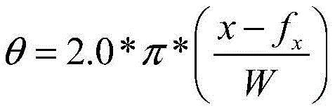
And (3) performing spherical projection expansion by using the internal reference of the fisheye camera and the field angle of the calibrated image, wherein the preset polar coordinate conversion relation is shown as a formula (6):

wherein, (x, y) is the first pixel point coordinate on the target spherical expansion image, (f)x,fy) Is the focal length of the fisheye camera, fxIs the horizontal focal length, f, of the fisheye camerayIs the vertical focal length of the fisheye camera, W is the preset width of the target spherical expansion image, H is the preset height of the target spherical expansion image, is the polar coordinate of the first pixel point.
The first preset mapping relationship is shown in formula (7):

wherein, (X, Y, Z) is the second pixel point coordinate which maps the first pixel point to the preset unit spherical surface.
The second preset mapping relationship is shown as equation (8):
α=atan2(Z,X)


u=Cx+Rx*cos(α)
v=Cy+Ry*sin(α)
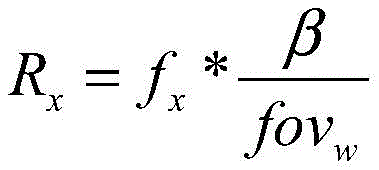
wherein alpha is an included angle between a first connecting line and a horizontal axis in a coordinate axis in which the preset unit spherical surface is located, the first connecting line is a connecting line between the second pixel point and the center of the preset unit spherical surface, beta is an included angle between the first connecting line and a vertical axis in the coordinate axis in which the preset unit spherical surface is located, fovwWidth-oriented field of view of calibration images acquired for fisheye cameras, fovhHeight-wise field of view, R, of a calibration image acquired for a fisheye cameraxIs the horizontal distance, R, from the second pixel point to the center of the sphereyIs the vertical distance from the second pixel point to the center of the sphere, (C)x,Cy) And (u, v) is the coordinate of a third pixel point which has a mapping relation with the first pixel point on the calibration image.
Obviously, no matter the collected video is cut or the collected video is not in a standard circle shape or the main point is deviated, the internal parameter is the only parameter capable of really reflecting the deviation of the main point and the change of the focal length, and the internal parameter of the fisheye camera is used in the spherical projection link in the process of establishing the panoramic synthetic mapping table, so that the spherical projection effect can be obviously improved, and the correction effect of the image after the spherical surface is unfolded is ensured.
And S103, splicing the videos to be spliced according to the splicing relation to synthesize the panoramic video.
Through off-line calibration, for a pair of fisheye equipment with two fisheye cameras of which the relative positions are fixed, only the panoramic synthesis mapping table needs to be stored, when the video is collected by the pair of fisheye equipment, the original video shot by the two fisheye cameras is checked by the panoramic synthesis mapping table to obtain the video to be spliced, and the video to be spliced is spliced to generate the panoramic video. The stitching relationship gives the stitching mode of each video to be stitched, for example, the first column of pixels of the second video to be stitched is overlapped with the twentieth column of pixels of the first video to be stitched, the second video to be stitched is overlapped with the first video to be stitched after being turned by 45 degrees, and the like.
The panoramic synthesis mapping table is established based on the calibration image, so that when video splicing is carried out, video frames can be spliced, and then video synthesis is carried out on the spliced video frames to obtain the panoramic video.
Optionally, S102 may include:
generating video frames to be spliced corresponding to the video frames and a splicing relation between the video frames to be spliced by searching a pre-established panoramic synthesis mapping table aiming at each video frame in each original video;
generating a video to be spliced by aiming at each video frame to be spliced generated by the same original video through a preset video generation technology;
s103 may include:
according to the splicing relation among the video frames to be spliced, respectively splicing the corresponding video frames to be spliced in the videos to be spliced to obtain a plurality of spliced images;
respectively carrying out three-dimensional projection on each spliced image according to a preset three-dimensional projection strategy to obtain a three-dimensional panoramic image corresponding to the spliced image;
and generating a panoramic video by a preset video generation technology based on each three-dimensional panoramic image.
The method comprises the steps that video frames to be spliced corresponding to the video frames in an original video and the splicing relation among the video frames to be spliced can be obtained based on a panoramic synthesis mapping table, the video to be spliced can be generated by a preset video generation technology due to the fact that the video is generated by the video frames, and when the video is generated, the sequence and the playing speed of the video frames in the video are regulated in the preset video generation technology. The method comprises the steps of splicing corresponding video frames to be spliced to obtain a plurality of spliced images based on the splicing relation among the video frames to be spliced, performing three-dimensional projection on the spliced images through a three-dimensional projection strategy, and performing video conversion on a three-dimensional panoramic image obtained after the three-dimensional projection by utilizing a preset video generation technology to generate a panoramic video. Of course, the panoramic video may be generated by generating a two-dimensional video by a stitching technique and then performing three-dimensional projection on the two-dimensional video to obtain the panoramic video.
Optionally, S103 may specifically be:
splicing the videos to be spliced according to the splicing relation to generate a two-dimensional video;
and performing three-dimensional projection on the two-dimensional video according to a preset three-dimensional projection strategy to obtain the panoramic video.
When the original video is shot by the double-fisheye device, the original video shot by the two fisheye cameras is subjected to table look-up by using the panorama synthesis mapping table to obtain two videos to be spliced, the two videos to be spliced are spliced according to the splicing relation to generate a two-dimensional video, and then the three-dimensional spherical panoramic video can be generated by performing spherical rendering on the two-dimensional video. The two-dimensional videos are spliced firstly and then projected onto the corresponding three-dimensional models according to the preset three-dimensional projection strategy, so that various three-dimensional panoramic display forms can be supported, and the display mode of the double-fisheye equipment is expanded.
As shown in fig. 5, when the original video is shot by the double-fisheye device, video frames shot by the two fisheye cameras can be extracted from the original video, a panorama synthesis mapping table is used for table lookup to obtain two sub-images to be spliced, the two sub-images to be spliced are subjected to image splicing to obtain a pair of two-dimensional panoramic images, a two-dimensional panoramic video is generated by a video generation technology, and the three-dimensional spherical panoramic video can be generated by spherical rendering of the two-dimensional panoramic video. The two-dimensional panoramic video can generate a corresponding three-dimensional spherical panoramic video through projection modes such as cylindrical projection and cubic projection. Of course, the two-dimensional panoramic image may be first subjected to spherical projection to obtain a three-dimensional panoramic image, and a three-dimensional spherical panoramic video is generated through a video generation technology, which is not specifically limited herein.
By applying the embodiment, the original videos respectively shot by the two fisheye cameras in the double-fisheye equipment are obtained; respectively generating videos to be spliced corresponding to the original videos and a splicing relation among the videos to be spliced by searching a pre-established panoramic synthesis mapping table aiming at each original video; and splicing the videos to be spliced according to the splicing relation to synthesize the panoramic video. The panoramic synthesis mapping table is obtained by respectively processing each calibration image based on the external parameters of the fisheye cameras calibrated in the calibration images acquired by each fisheye camera, the internal parameters of each fisheye camera calibrated by a preset Zhang Zhengyou calibration method in a preset specified calibration field and the angle of view of the calibration images acquired by each fisheye camera; when the panoramic video is synthesized, video splicing can be completed according to the panoramic synthesis mapping table; the external parameters, the internal parameters and the field angles of all the fisheye cameras are used as fixed parameters of all the fisheye cameras, and the main point offset, the focal length change and the like of the cameras can be reflected uniquely, so that no matter whether the video shot by the fisheye equipment is cut or not in a standard circle shape, the panoramic video can be synthesized according to the table look-up operation of the panoramic synthesis mapping table, and the splicing errors generated when the shot video is cut or not in the standard circle shape are effectively avoided. And moreover, an off-line calibration mode is adopted, one pair of fisheye equipment is calibrated once, and a panoramic video is obtained by looking up a panoramic synthesis mapping table, so that the calculation expense is saved.
Corresponding to the above method embodiment, an embodiment of the present invention further provides a panoramic video synthesis apparatus, as shown in fig. 6, where the panoramic video synthesis apparatus includes:
the acquiring module 610 is configured to acquire original videos respectively captured by two fisheye cameras in the dual-fisheye device;
the searching module 620 is configured to search a pre-established panoramic synthesis mapping table, and generate videos to be stitched corresponding to the original videos and a stitching relationship between the videos to be stitched for each original video, respectively, where the panoramic synthesis mapping table is obtained by processing each calibrated image based on an external parameter of a fisheye camera calibrated in a calibrated image acquired by each fisheye camera, an internal parameter of each fisheye camera calibrated by a preset Zhang Zhengyou calibration method in a pre-established specified calibration site, and a field angle of the calibrated image acquired by each fisheye camera;
and the splicing module 630 is configured to splice the videos to be spliced according to the splicing relationship to synthesize a panoramic video.
Optionally, the obtaining module 610 may be further configured to:
acquiring calibration images respectively acquired by the two fisheye cameras, external parameters of the fisheye cameras calibrated in the calibration images and the field angles of the calibration images;
obtaining internal parameters of each fisheye camera by using a preset Zhang Zhengyou calibration method in a preset specified calibration field;
the apparatus may further include:
the projection expansion module is used for respectively performing spherical projection expansion on each calibration image according to the internal reference of each fisheye camera and the field angle of the calibration image acquired by each fisheye camera to generate a spherical expansion image corresponding to the calibration image;
the acquisition module is used for acquiring the relative position relation between the spherical expansion images according to the external parameters of the fisheye cameras;
and the processing module is used for processing each spherical expansion image according to the relative position relation to obtain a panoramic synthesis mapping table.
Optionally, the obtaining module 610 may be further configured to:
acquiring calibration images respectively acquired by the two fisheye cameras, external parameters of the fisheye cameras calibrated in the calibration images and the field angles of the calibration images;
obtaining internal parameters of each fisheye camera by using a preset Zhang Zhengyou calibration method in a preset specified calibration field;
the apparatus may further include:
the device comprises an establishing module, a judging module and a judging module, wherein the establishing module is used for establishing a first panorama mapping table, and the content of the first panorama mapping table is empty;
the obtaining module is used for obtaining the relative position relation between preset areas in the first panorama mapping table according to the external parameters of the fisheye cameras;
the inverse transformation module is used for carrying out inverse transformation on each preset region according to the relative position relation to obtain an inverse transformation region of the preset region;
the projection expansion module is used for respectively performing spherical projection expansion on each calibration image according to the internal reference of each fisheye camera and the field angle of the calibration image acquired by each fisheye camera to generate a spherical expansion image corresponding to the calibration image;
and the determining module is used for determining the panoramic synthesis mapping table according to the corresponding relation between each spherical expansion image and each inverse transformation area.
Optionally, the internal reference of the fisheye camera includes: the principal point coordinate and the focal length of the fisheye camera;
the projection expansion module may be specifically configured to:
acquiring coordinates of a first pixel point on a target spherical expansion image, and a preset width and a preset height of the target spherical expansion image, wherein the first pixel point is any pixel point on the target spherical expansion image;
obtaining the polar coordinate of the first pixel point through a preset polar coordinate conversion relation according to the focal length of the fisheye camera, the first pixel point coordinate, the preset width and the preset height;
according to the polar coordinates of the first pixel points, obtaining second pixel point coordinates which map the first pixel points to the preset unit spherical surface through a first preset mapping relation between the polar coordinates and pixel point coordinates on the preset unit spherical surface;
according to the second pixel point coordinate, the main point coordinate of the fisheye camera, the focal length of the fisheye camera and the field angle of the calibration image acquired by the fisheye camera, a third pixel point coordinate which has a mapping relation with the first pixel point on the calibration image is obtained through a second preset mapping relation of the pixel point coordinate on the preset unit spherical surface and the pixel point coordinate on the calibration image;
and according to the calculated mapping relation between each pixel point on the target spherical expansion image and each pixel point on the calibration image, taking the target spherical expansion image obtained by mapping as the spherical expansion image of the calibration image.
Optionally, the preset polar coordinate transformation relationship may be:


wherein, (x, y) is the first pixel point coordinate on the target spherical expansion image, (f)x,fy) Is the focal length of the fisheye camera, fxIs the horizontal focal length of the fisheye camera, fyBeing fisheye camerasA focal length in the vertical direction, wherein W is a preset width of the target spherical expansion image, and H is a preset height of the target spherical expansion image, the polar coordinates of the first pixel point are obtained;
the first preset mapping relationship may be:


Z=sin(θ)
wherein, (X, Y, Z) is the second pixel point coordinate which maps the first pixel point to the preset unit spherical surface;
the second preset mapping relationship may be:
α=atan2(Z,X)


u=Cx+Rx*cos(α)
v=Cy+Ry*sin(α)
wherein α is an included angle between a first connection line and a transverse axis in a coordinate axis of the preset unit spherical surface, the first connection line is a connection line between the second pixel point and the spherical center of the preset unit spherical surface, and β is the first connection lineAn included angle between the line and a longitudinal axis in a coordinate axis of the preset unit spherical surface, fovwThe field angle of the width direction of the calibration image collected by the fisheye camera, fovhThe angle of view in the height direction of the calibration image collected for the fisheye camera, RxIs the horizontal distance from the second pixel point to the center of the sphere, Ry(ii) the vertical distance from the second pixel point to the center of the sphere, (C)x,Cy) And (u, v) is the coordinate of a third pixel point which has a mapping relation with the first pixel point on the calibration image.
Optionally, the panoramic synthesis mapping table includes respective mapping tables of the two fisheye cameras, and an overlapping area with the same content exists between the mapping tables of the two fisheye cameras.
Optionally, the search module 620 may be specifically configured to:
generating video frames to be spliced corresponding to the video frames and a splicing relation between the video frames to be spliced by searching a pre-established panoramic synthesis mapping table aiming at each video frame in each original video;
generating a video to be spliced by aiming at each video frame to be spliced generated by the same original video through a preset video generation technology;
the splicing module 630 may be specifically configured to:
according to the splicing relation among the video frames to be spliced, respectively splicing the corresponding video frames to be spliced in the videos to be spliced to obtain a plurality of spliced images;
respectively carrying out three-dimensional projection on each spliced image according to a preset three-dimensional projection strategy to obtain a three-dimensional panoramic image corresponding to the spliced image;
and generating a panoramic video by a preset video generation technology based on each three-dimensional panoramic image.
Optionally, the splicing module 630 may be specifically configured to:
according to the splicing relation, splicing the videos to be spliced to generate a two-dimensional video;
and performing three-dimensional projection on the two-dimensional video according to a preset three-dimensional projection strategy to obtain a panoramic video.
By applying the embodiment, the original videos respectively shot by the two fisheye cameras in the double-fisheye equipment are obtained; respectively generating videos to be spliced corresponding to the original videos and a splicing relation among the videos to be spliced by searching a pre-established panoramic synthesis mapping table aiming at each original video; and splicing the videos to be spliced according to the splicing relation to synthesize the panoramic video. The panoramic synthesis mapping table is obtained by respectively processing each calibration image based on the external parameters of the fisheye cameras calibrated in the calibration images acquired by each fisheye camera, the internal parameters of each fisheye camera calibrated by a preset Zhang Zhengyou calibration method in a preset specified calibration field and the angle of view of the calibration images acquired by each fisheye camera; when the panoramic video is synthesized, video splicing can be completed according to the panoramic synthesis mapping table; the external parameters, the internal parameters and the field angles of all the fisheye cameras are used as fixed parameters of all the fisheye cameras, and the main point offset, the focal length change and the like of the cameras can be reflected uniquely, so that no matter whether the video shot by the fisheye equipment is cut or not in a standard circle shape, the panoramic video can be synthesized according to the table look-up operation of the panoramic synthesis mapping table, and the splicing errors generated when the shot video is cut or not in the standard circle shape are effectively avoided.
Embodiments of the present invention also provide an electronic device, as shown in fig. 7, which may include a processor 701 and a memory 702, wherein,
the memory 702 is used for storing computer programs;
the processor 701 is configured to implement all the steps of the panoramic video synthesis method provided by the embodiment of the present invention when executing the program stored in the memory 702.
The Memory may include a RAM (Random Access Memory) or an NVM (Non-Volatile Memory), such as at least one disk Memory. Optionally, the memory may also be at least one memory device located remotely from the processor.
The Processor may be a general-purpose Processor, including a Central Processing Unit (CPU), a Network Processor (NP), and the like; but also a DSP (Digital Signal Processor), an ASIC (Application Specific Integrated Circuit), an FPGA (Field-Programmable Gate Array) or other Programmable logic device, discrete Gate or transistor logic device, discrete hardware component.
Through above-mentioned electronic equipment, can realize: original videos shot by two fisheye cameras in the double-fisheye equipment are obtained; respectively generating videos to be spliced corresponding to the original videos and a splicing relation among the videos to be spliced by searching a pre-established panoramic synthesis mapping table aiming at each original video; and splicing the videos to be spliced according to the splicing relation to synthesize the panoramic video. The panoramic synthesis mapping table is obtained by respectively processing each calibration image based on the external parameters of the fisheye cameras calibrated in the calibration images acquired by each fisheye camera, the internal parameters of each fisheye camera calibrated by a preset Zhang Zhengyou calibration method in a preset specified calibration field and the angle of view of the calibration images acquired by each fisheye camera; when the panoramic video is synthesized, video splicing can be completed according to the panoramic synthesis mapping table; the external parameters, the internal parameters and the field angles of all the fisheye cameras are used as fixed parameters of all the fisheye cameras, and the main point offset, the focal length change and the like of the cameras can be reflected uniquely, so that no matter whether the video shot by the fisheye equipment is cut or not in a standard circle shape, the panoramic video can be synthesized according to the table look-up operation of the panoramic synthesis mapping table, and the splicing errors generated when the shot video is cut or not in the standard circle shape are effectively avoided.
In addition, corresponding to the panoramic video synthesis method provided by the above embodiment, an embodiment of the present invention provides a computer-readable storage medium, in which a computer program is stored, and the computer program, when executed by a processor, implements all the steps of the panoramic video synthesis method provided by the embodiment of the present invention.
The above-mentioned computer-readable storage medium stores an application program that executes the panoramic video composition method provided by the embodiment of the present invention when executed, and thus can implement: original videos shot by two fisheye cameras in the double-fisheye equipment are obtained; respectively generating videos to be spliced corresponding to the original videos and a splicing relation among the videos to be spliced by searching a pre-established panoramic synthesis mapping table aiming at each original video; and splicing the videos to be spliced according to the splicing relation to synthesize the panoramic video. The panoramic synthesis mapping table is obtained by respectively processing each calibration image based on the external parameters of the fisheye cameras calibrated in the calibration images acquired by each fisheye camera, the internal parameters of each fisheye camera calibrated by a preset Zhang Zhengyou calibration method in a preset specified calibration field and the angle of view of the calibration images acquired by each fisheye camera; when the panoramic video is synthesized, video splicing can be completed according to the panoramic synthesis mapping table; the external parameters, the internal parameters and the field angles of all the fisheye cameras are used as fixed parameters of all the fisheye cameras, and the main point offset, the focal length change and the like of the cameras can be reflected uniquely, so that no matter the video shot by the fisheye equipment is cut or is not in a standard circle shape, the panoramic video can be synthesized according to the table look-up operation of the panoramic synthesis mapping table, and the splicing error caused when the shot video is cut or is not in the standard circle shape is effectively avoided.
For the embodiments of the electronic device and the computer-readable storage medium, since the contents of the related methods are substantially similar to those of the foregoing embodiments of the methods, the description is relatively simple, and for the relevant points, reference may be made to the partial description of the embodiments of the methods.
It is noted that, herein, relational terms such as first and second, and the like may be used solely to distinguish one entity or action from another entity or action without necessarily requiring or implying any actual such relationship or order between such entities or actions. Also, the terms "comprises," "comprising," or any other variation thereof, are intended to cover a non-exclusive inclusion, such that a process, method, article, or apparatus that comprises a list of elements does not include only those elements but may include other elements not expressly listed or inherent to such process, method, article, or apparatus. Without further limitation, an element defined by the phrase "comprising an … …" does not exclude the presence of other identical elements in a process, method, article, or apparatus that comprises the element.
All the embodiments in the present specification are described in a related manner, and the same and similar parts among the embodiments may be referred to each other, and each embodiment focuses on the differences from the other embodiments. In particular, for the embodiments of the apparatus, the electronic device, and the computer-readable storage medium, since they are substantially similar to the embodiments of the method, the description is simple, and for the relevant points, reference may be made to the partial description of the embodiments of the method.
The above description is only for the preferred embodiment of the present invention, and is not intended to limit the scope of the present invention. Any modification, equivalent replacement, or improvement made within the spirit and principle of the present invention shall fall within the protection scope of the present invention.
Claims (16)
1. A method for panoramic video synthesis, the method comprising:
acquiring original videos respectively shot by two fisheye cameras in the double-fisheye equipment;
respectively generating videos to be spliced corresponding to the original videos and a splicing relation among the videos to be spliced aiming at the original videos by searching a pre-established panoramic synthesis mapping table, wherein the panoramic synthesis mapping table is obtained by respectively processing spherical expansion images obtained by carrying out spherical projection expansion on all calibration images based on external parameters of fisheye cameras calibrated in calibration images acquired by all fisheye cameras, internal parameters of all fisheye cameras calibrated in a pre-established specified calibration field by using a preset Zhang-up friend calibration method and field angles of the calibration images acquired by all fisheye cameras;
splicing the videos to be spliced according to the splicing relation to synthesize a panoramic video;
wherein, the internal reference of fisheye camera includes: the principal point coordinate and the focal length of the fisheye camera;
the method for generating the spherical expansion image comprises the following steps:
acquiring coordinates of a first pixel point on a target spherical expansion image, and a preset width and a preset height of the target spherical expansion image, wherein the first pixel point is any pixel point on the target spherical expansion image;
obtaining the polar coordinate of the first pixel point through a preset polar coordinate conversion relation according to the focal length of the fisheye camera, the first pixel point coordinate, the preset width and the preset height;
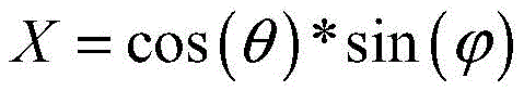
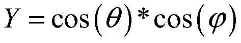
according to the polar coordinate of the first pixel point, obtaining a second pixel point coordinate which maps the first pixel point to a preset unit spherical surface through a first preset mapping relation between the polar coordinate and a pixel point coordinate on the preset unit spherical surface, wherein the first preset mapping relation is as follows:


Z=sin(θ)
(X, Y, Z) is the second pixel point coordinate which maps the first pixel point to the preset unit spherical surface, the polar coordinates of the first pixel point are obtained;
according to the second pixel point coordinate, the main point coordinate of the fisheye camera, the focal length of the fisheye camera and the field angle of the calibration image collected by the fisheye camera, a third pixel point coordinate which has a mapping relation with the first pixel point on the calibration image is obtained through a second preset mapping relation of the pixel point coordinate on the preset unit spherical surface and the pixel point coordinate on the calibration image, wherein the second preset mapping relation is as follows:
α=atan2(Z,X)


u=Cx+Rx*cos(α)
v=Cy+Ry*sin(α)
wherein α is an included angle between a first connection line and a horizontal axis in a coordinate axis in which the preset unit spherical surface is located, the first connection line is a connection line between the second pixel point and a spherical center of the preset unit spherical surface, β is an included angle between the first connection line and a longitudinal axis in the coordinate axis in which the preset unit spherical surface is located, and fovwThe field angle of the width direction of the calibration image collected by the fisheye camera, fovhThe angle of view in the height direction of the calibration image collected for the fisheye camera, RxIs the horizontal distance from the second pixel point to the center of the sphere, Ry(ii) the vertical distance from the second pixel point to the center of the sphere, (C)x,Cy) The coordinate of a principal point of the fisheye camera is (u, v) the coordinate of a third pixel point which has a mapping relation with the first pixel point on the calibration image;
and according to the calculated mapping relation between each pixel point on the target spherical expansion image and each pixel point on the calibration image, taking the target spherical expansion image obtained by mapping as the spherical expansion image of the calibration image.
2. The method of claim 1, wherein the panorama synthesis mapping table is established in a manner that includes:
acquiring calibration images respectively acquired by the two fisheye cameras, external parameters of the fisheye cameras calibrated in the calibration images and the field angles of the calibration images;
obtaining internal parameters of each fisheye camera by using a preset Zhang Zhengyou calibration method in a preset specified calibration field;
according to the internal parameters of each fisheye camera and the field angle of the calibration image collected by each fisheye camera, performing spherical projection expansion on each calibration image respectively to generate a spherical expansion image corresponding to the calibration image;
obtaining the relative position relation between the spherical expansion images according to the external parameters of the fisheye cameras;
and processing each spherical expansion image according to the relative position relationship to obtain a panoramic synthesis mapping table.
3. The method of claim 1, wherein the panorama synthesis mapping table is established in a manner that includes:
acquiring calibration images respectively acquired by the two fisheye cameras, external parameters of the fisheye cameras calibrated in the calibration images and the field angles of the calibration images;
obtaining internal parameters of each fisheye camera by using a preset Zhang Zhengyou calibration method in a preset specified calibration field;
establishing a first panoramic mapping table, wherein the content of the first panoramic mapping table is empty;
obtaining the relative position relation between preset areas in the first panorama mapping table according to the external parameters of the fisheye cameras;
according to the relative position relation, carrying out inverse transformation on each preset area to obtain an inverse transformation area of the preset area;
according to the internal parameters of each fisheye camera and the field angle of the calibration image collected by each fisheye camera, performing spherical projection expansion on each calibration image respectively to generate a spherical expansion image corresponding to the calibration image;
and determining a panoramic synthesis mapping table according to the corresponding relation between each spherical expansion image and each inverse transformation area.
4. The method of claim 1, wherein the predetermined polar transformation relationship is:


wherein, (x, y) is the first pixel point coordinate on the target spherical expansion image, (f)x,fy) Is the focal length of the fisheye camera, fxIs the horizontal focal length of the fisheye camera, fyIs the vertical focal length of the fisheye camera, the W is the preset width of the target spherical expansion image, the H is the preset height of the target spherical expansion image, and the polar coordinates of the first pixel point are obtained.
5. The method according to claim 2 or 3, wherein the panorama synthesis mapping table comprises respective mapping tables of the two fisheye cameras, and there is an overlapping area with the same content between the mapping tables of the two fisheye cameras.
6. The method according to claim 1, wherein the generating the videos to be stitched corresponding to the original videos and the stitching relationship between the videos to be stitched for each original video by searching a pre-established panorama synthesis mapping table comprises:
generating video frames to be spliced corresponding to the video frames and a splicing relation between the video frames to be spliced by searching a pre-established panoramic synthesis mapping table aiming at each video frame in each original video;
generating a video to be spliced by aiming at each video frame to be spliced generated by the same original video through a preset video generation technology;
according to the splicing relation, splicing the videos to be spliced to synthesize a panoramic video, comprising the following steps:
according to the splicing relation among the video frames to be spliced, respectively splicing the corresponding video frames to be spliced in the videos to be spliced to obtain a plurality of spliced images;
respectively carrying out three-dimensional projection on each spliced image according to a preset three-dimensional projection strategy to obtain a three-dimensional panoramic image corresponding to the spliced image;
and generating a panoramic video by a preset video generation technology based on each three-dimensional panoramic image.
7. The method according to claim 1, wherein the splicing the videos to be spliced according to the splicing relationship to synthesize a panoramic video comprises:
according to the splicing relation, splicing the videos to be spliced to generate a two-dimensional video;
and performing three-dimensional projection on the two-dimensional video according to a preset three-dimensional projection strategy to obtain a panoramic video.
8. A panoramic video composition apparatus, characterized in that the apparatus comprises:
the acquisition module is used for acquiring original videos respectively shot by two fisheye cameras in the double-fisheye equipment;
the panoramic synthesis mapping table is used for respectively generating videos to be spliced corresponding to the original videos and splicing relations among the videos to be spliced according to the original videos by searching a pre-established panoramic synthesis mapping table, wherein the panoramic synthesis mapping table is obtained by respectively processing spherical expansion images obtained by carrying out spherical projection expansion on each calibration image based on external parameters of a fisheye camera calibrated in a calibration image acquired by each fisheye camera, internal parameters of each fisheye camera calibrated by a preset Zhang Zhengyou calibration method in a pre-established specified calibration field and a field angle of the calibration image acquired by each fisheye camera;
the splicing module is used for splicing the videos to be spliced according to the splicing relation to synthesize a panoramic video;
wherein, the internal reference of fisheye camera includes: the principal point coordinate and the focal length of the fisheye camera;
the apparatus also includes a projection expansion module to:
acquiring coordinates of a first pixel point on a target spherical expansion image, and a preset width and a preset height of the target spherical expansion image, wherein the first pixel point is any pixel point on the target spherical expansion image;
obtaining the polar coordinate of the first pixel point through a preset polar coordinate conversion relation according to the focal length of the fisheye camera, the first pixel point coordinate, the preset width and the preset height;
according to the polar coordinate of the first pixel point, obtaining a second pixel point coordinate which maps the first pixel point to a preset unit spherical surface through a first preset mapping relation between the polar coordinate and a pixel point coordinate on the preset unit spherical surface, wherein the first preset mapping relation is as follows:


Z=sin(θ)
(X, Y, Z) is the second pixel point coordinate which maps the first pixel point to the preset unit spherical surface;
according to the second pixel point coordinate, the main point coordinate of the fisheye camera, the focal length of the fisheye camera and the field angle of the calibration image collected by the fisheye camera, a third pixel point coordinate which has a mapping relation with the first pixel point on the calibration image is obtained through a second preset mapping relation of the pixel point coordinate on the preset unit spherical surface and the pixel point coordinate on the calibration image, wherein the second preset mapping relation is as follows:
α=atan2(Z,X)


u=Cx+Rx*cos(α)
v=Cy+Ry*sin(α)
wherein α is an included angle between a first connection line and a horizontal axis in a coordinate axis in which the preset unit spherical surface is located, the first connection line is a connection line between the second pixel point and a spherical center of the preset unit spherical surface, β is an included angle between the first connection line and a longitudinal axis in the coordinate axis in which the preset unit spherical surface is located, and fovwThe field angle of the width direction of the calibration image collected by the fisheye camera, fovhThe angle of view in the height direction of the calibration image collected for the fisheye camera, RxIs the horizontal distance from the second pixel point to the center of the sphere, Ry(ii) the vertical distance from the second pixel point to the center of the sphere, (C)x,Cy) The coordinate of a principal point of the fisheye camera is (u, v) the coordinate of a third pixel point which has a mapping relation with the first pixel point on the calibration image;
and according to the calculated mapping relation between each pixel point on the target spherical expansion image and each pixel point on the calibration image, taking the target spherical expansion image obtained by mapping as the spherical expansion image of the calibration image.
9. The apparatus of claim 8, wherein the obtaining module is further configured to:
acquiring calibration images respectively acquired by the two fisheye cameras, external parameters of the fisheye cameras calibrated in the calibration images and the field angles of the calibration images;
obtaining internal parameters of each fisheye camera by using a preset Zhang Zhengyou calibration method in a preset specified calibration field;
the projection expansion module is used for respectively performing spherical projection expansion on each calibration image according to the internal parameters of each fisheye camera and the field angle of the calibration image acquired by each fisheye camera to generate a spherical expansion image corresponding to the calibration image;
the device further comprises:
the acquisition module is used for acquiring the relative position relation between the spherical expansion images according to the external parameters of the fisheye cameras;
and the processing module is used for processing each spherical expansion image according to the relative position relation to obtain a panoramic synthesis mapping table.
10. The apparatus of claim 8, wherein the obtaining module is further configured to:
acquiring calibration images respectively acquired by the two fisheye cameras, external parameters of the fisheye cameras calibrated in the calibration images and the field angles of the calibration images;
obtaining internal parameters of each fisheye camera by using a preset Zhang Zhengyou calibration method in a preset specified calibration field;
the device further comprises:
the device comprises an establishing module, a judging module and a judging module, wherein the establishing module is used for establishing a first panorama mapping table, and the content of the first panorama mapping table is empty;
the obtaining module is used for obtaining the relative position relation between preset areas in the first panorama mapping table according to the external parameters of the fisheye cameras;
the inverse transformation module is used for carrying out inverse transformation on each preset region according to the relative position relation to obtain an inverse transformation region of the preset region;
the projection expansion module is used for respectively performing spherical projection expansion on each calibration image according to the internal reference of each fisheye camera and the field angle of the calibration image acquired by each fisheye camera to generate a spherical expansion image corresponding to the calibration image;
and the determining module is used for determining the panoramic synthesis mapping table according to the corresponding relation between each spherical expansion image and each inverse transformation area.
11. The apparatus of claim 8, wherein the predetermined polar coordinate transformation relationship is:


wherein, (x, y) is the first pixel point coordinate on the target spherical expansion image, (f)x,fy) Is the focal length of the fisheye camera, fxIs the horizontal focal length of the fisheye camera, fyIs the vertical focal length of the fisheye camera, the W is the preset width of the target spherical expansion image, the H is the preset height of the target spherical expansion image, and the polar coordinates of the first pixel point are obtained.
12. The apparatus according to claim 9 or 10, wherein the panorama synthesis mapping table comprises respective mapping tables of the two fisheye cameras, and there is an overlapping area with the same content between the mapping tables of the two fisheye cameras.
13. The apparatus of claim 8, wherein the lookup module is specifically configured to:
generating video frames to be spliced corresponding to the video frames and a splicing relation between the video frames to be spliced by searching a pre-established panoramic synthesis mapping table aiming at each video frame in each original video;
generating a video to be spliced by aiming at each video frame to be spliced generated by the same original video through a preset video generation technology;
the splicing module is specifically configured to:
according to the splicing relation among the video frames to be spliced, respectively splicing the corresponding video frames to be spliced in the videos to be spliced to obtain a plurality of spliced images;
respectively carrying out three-dimensional projection on each spliced image according to a preset three-dimensional projection strategy to obtain a three-dimensional panoramic image corresponding to the spliced image;
and generating a panoramic video by a preset video generation technology based on each three-dimensional panoramic image.
14. The apparatus of claim 8, wherein the splicing module is specifically configured to:
according to the splicing relation, splicing the videos to be spliced to generate a two-dimensional video;
and performing three-dimensional projection on the two-dimensional video according to a preset three-dimensional projection strategy to obtain a panoramic video.
15. An electronic device comprising a processor and a memory, wherein,
the memory is used for storing a computer program;
the processor, when executing the program stored in the memory, implementing the method steps of any of claims 1-7.
16. A computer-readable storage medium, characterized in that a computer program is stored in the computer-readable storage medium, which computer program, when being executed by a processor, carries out the method steps of any one of claims 1 to 7.
Priority Applications (1)
| Application Number | Priority Date | Filing Date | Title |
|---|---|---|---|
| CN201810496114.8A CN110519528B (en) | 2018-05-22 | 2018-05-22 | A panoramic video synthesis method, device and electronic device |
Applications Claiming Priority (1)
| Application Number | Priority Date | Filing Date | Title |
|---|---|---|---|
| CN201810496114.8A CN110519528B (en) | 2018-05-22 | 2018-05-22 | A panoramic video synthesis method, device and electronic device |
Publications (2)
| Publication Number | Publication Date |
|---|---|
| CN110519528A CN110519528A (en) | 2019-11-29 |
| CN110519528B true CN110519528B (en) | 2021-09-24 |
Family
ID=68622080
Family Applications (1)
| Application Number | Title | Priority Date | Filing Date |
|---|---|---|---|
| CN201810496114.8A Active CN110519528B (en) | 2018-05-22 | 2018-05-22 | A panoramic video synthesis method, device and electronic device |
Country Status (1)
| Country | Link |
|---|---|
| CN (1) | CN110519528B (en) |
Families Citing this family (14)
| Publication number | Priority date | Publication date | Assignee | Title |
|---|---|---|---|---|
| CN111738909B (en) * | 2020-06-11 | 2023-09-26 | 杭州海康威视数字技术股份有限公司 | An image generation method and device |
| CN111862240B (en) * | 2020-07-28 | 2022-10-04 | 展讯通信(上海)有限公司 | Panoramic camera and calibration method thereof, panoramic image splicing method and storage medium |
| CN112770095B (en) * | 2021-01-28 | 2023-06-30 | 广州方硅信息技术有限公司 | Panoramic projection method and device and electronic equipment |
| CN112907447B (en) * | 2021-02-08 | 2022-07-01 | 杭州海康威视数字技术股份有限公司 | Splicing of sky cloud pictures and method for determining installation positions of multiple cameras |
| CN113132708B (en) * | 2021-04-22 | 2022-02-22 | 贝壳找房(北京)科技有限公司 | Method and apparatus for acquiring three-dimensional scene image using fisheye camera, device and medium |
| CN113793382B (en) * | 2021-08-04 | 2024-10-18 | 北京旷视科技有限公司 | Video image seam search method, video image splicing method and device |
| CN115731384B (en) * | 2021-08-30 | 2026-03-24 | 影石创新科技股份有限公司 | Fisheye image semantic segmentation methods, apparatus, computer equipment, and storage media |
| CN114511831B (en) * | 2022-01-14 | 2025-07-22 | 北京经纬恒润科技股份有限公司 | Detection method and system based on visual drivable area |
| CN114648590B (en) * | 2022-03-01 | 2026-03-10 | 杭州海康威视数字技术股份有限公司 | Camera parameter calibration method and device, processor and vehicle |
| CN115272251A (en) * | 2022-08-01 | 2022-11-01 | 推移机器人科技(苏州)有限责任公司 | Perception system and method for double-fish glasses heads |
| CN115984348A (en) * | 2022-12-13 | 2023-04-18 | 抖音视界有限公司 | A panoramic image processing method, device, electronic equipment and storage medium |
| CN116503492B (en) * | 2023-06-27 | 2024-06-14 | 北京鉴智机器人科技有限公司 | Binocular camera module calibration method and calibration device in automatic driving system |
| CN117809224B (en) * | 2024-01-05 | 2024-07-09 | 四川新视创伟超高清科技有限公司 | Panoramic monitoring image processing method and processing system |
| CN119067842B (en) * | 2024-08-09 | 2025-08-22 | 四川广信天下传媒有限责任公司 | A video fusion method and fusion system for fisheye cameras |
Citations (8)
| Publication number | Priority date | Publication date | Assignee | Title |
|---|---|---|---|---|
| CN102222337A (en) * | 2011-06-14 | 2011-10-19 | 重庆大学 | Fisheye image correcting method for image stitching |
| CN102298771A (en) * | 2011-08-16 | 2011-12-28 | 淮安盈科伟力科技有限公司 | Fish-eye image rapid correction method of panoramic parking auxiliary system |
| CN102509261A (en) * | 2011-10-10 | 2012-06-20 | 宁波大学 | Distortion correction method for fisheye lens |
| CN104835117A (en) * | 2015-05-11 | 2015-08-12 | 合肥工业大学 | Spherical panorama generating method based on overlapping way |
| CN106327478A (en) * | 2016-08-31 | 2017-01-11 | 北京的卢深视科技有限公司 | Fisheye panoramic image synthesis processing method and device |
| CN106791578A (en) * | 2016-12-26 | 2017-05-31 | 西安电子科技大学 | Video meeting implementing method based on flake panoramic camera |
| TW201741759A (en) * | 2016-05-18 | 2017-12-01 | Ulsee Inc | Three-dimensional panorama system of vehicle and method thereof including a fisheye image correction setting module and a static three-dimensional stitched image generation module |
| CN107958440A (en) * | 2017-12-08 | 2018-04-24 | 合肥工业大学 | Double fish eye images real time panoramic image split-joint methods and system are realized on GPU |
Family Cites Families (1)
| Publication number | Priority date | Publication date | Assignee | Title |
|---|---|---|---|---|
| US9915857B2 (en) * | 2013-12-09 | 2018-03-13 | Geo Semiconductor Inc. | System and method for automated test-pattern-free projection calibration |
-
2018
- 2018-05-22 CN CN201810496114.8A patent/CN110519528B/en active Active
Patent Citations (8)
| Publication number | Priority date | Publication date | Assignee | Title |
|---|---|---|---|---|
| CN102222337A (en) * | 2011-06-14 | 2011-10-19 | 重庆大学 | Fisheye image correcting method for image stitching |
| CN102298771A (en) * | 2011-08-16 | 2011-12-28 | 淮安盈科伟力科技有限公司 | Fish-eye image rapid correction method of panoramic parking auxiliary system |
| CN102509261A (en) * | 2011-10-10 | 2012-06-20 | 宁波大学 | Distortion correction method for fisheye lens |
| CN104835117A (en) * | 2015-05-11 | 2015-08-12 | 合肥工业大学 | Spherical panorama generating method based on overlapping way |
| TW201741759A (en) * | 2016-05-18 | 2017-12-01 | Ulsee Inc | Three-dimensional panorama system of vehicle and method thereof including a fisheye image correction setting module and a static three-dimensional stitched image generation module |
| CN106327478A (en) * | 2016-08-31 | 2017-01-11 | 北京的卢深视科技有限公司 | Fisheye panoramic image synthesis processing method and device |
| CN106791578A (en) * | 2016-12-26 | 2017-05-31 | 西安电子科技大学 | Video meeting implementing method based on flake panoramic camera |
| CN107958440A (en) * | 2017-12-08 | 2018-04-24 | 合肥工业大学 | Double fish eye images real time panoramic image split-joint methods and system are realized on GPU |
Non-Patent Citations (1)
| Title |
|---|
| 《基于改进球面透视投影的鱼眼图像畸变校正方法》;王向军 等;《计算机视觉》;20180319;第39卷(第1期);43-49 * |
Also Published As
| Publication number | Publication date |
|---|---|
| CN110519528A (en) | 2019-11-29 |
Similar Documents
| Publication | Publication Date | Title |
|---|---|---|
| CN110519528B (en) | A panoramic video synthesis method, device and electronic device | |
| CN110351494B (en) | A panoramic video synthesis method, device and electronic device | |
| CN114742797A (en) | Defect detection method for drainage pipeline inner wall panoramic image and image acquisition robot | |
| CN109547766A (en) | A kind of panorama image generation method and device | |
| CN106157304A (en) | A kind of Panoramagram montage method based on multiple cameras and system | |
| KR101342393B1 (en) | Georeferencing Method of Indoor Omni-Directional Images Acquired by Rotating Line Camera | |
| JP2005094048A (en) | Imaging apparatus and method with image correction function, and imaging apparatus and method | |
| CN110349077B (en) | Panoramic image synthesis method and device and electronic equipment | |
| CN108200360A (en) | A kind of real-time video joining method of more fish eye lens panoramic cameras | |
| WO2021184302A1 (en) | Image processing method and apparatus, imaging device, movable carrier, and storage medium | |
| CN108074250B (en) | Matching cost calculation method and device | |
| CN117422650B (en) | Panoramic image distortion correction method and device, electronic equipment and medium | |
| CN118646833B (en) | Panorama stitching method and device, electronic equipment and storage medium | |
| US20140009587A1 (en) | Mobile communication terminal having image conversion function and method | |
| JP2005275789A (en) | 3D structure extraction method | |
| CN101354790A (en) | Unfolding method of N-plane perspective panorama of omnidirectional camera based on Taylor series model | |
| CN110796690B (en) | Image matching method and image matching device | |
| JP2024072284A (en) | 3D calibration method and apparatus for multi-view phase shift profilometry - Patents.com | |
| CN114862959B (en) | Method and apparatus for controlling a camera | |
| Amini et al. | Development of a new stereo‐panorama system based on off‐the‐shelf stereo cameras | |
| CN114026600A (en) | Camera calibration method | |
| Gao et al. | Real‐time mosaic of multiple fisheye surveillance videos based on geo‐registration and rectification | |
| CN116503240A (en) | A method and system for configuring and splicing panoramic pictures of annular rotating ground projection | |
| DeChant et al. | A close-range photogrammetric solution working with zoomed images from digital cameras | |
| JP6439845B2 (en) | Image processing device |
Legal Events
| Date | Code | Title | Description |
|---|---|---|---|
| PB01 | Publication | ||
| PB01 | Publication | ||
| SE01 | Entry into force of request for substantive examination | ||
| SE01 | Entry into force of request for substantive examination | ||
| GR01 | Patent grant | ||
| GR01 | Patent grant |