CN1105809C - Synthetic aouatic structure - Google Patents
Synthetic aouatic structure Download PDFInfo
- Publication number
- CN1105809C CN1105809C CN98106999A CN98106999A CN1105809C CN 1105809 C CN1105809 C CN 1105809C CN 98106999 A CN98106999 A CN 98106999A CN 98106999 A CN98106999 A CN 98106999A CN 1105809 C CN1105809 C CN 1105809C
- Authority
- CN
- China
- Prior art keywords
- artificial
- layer
- surface area
- waterweed
- high surface
- Prior art date
- Legal status (The legal status is an assumption and is not a legal conclusion. Google has not performed a legal analysis and makes no representation as to the accuracy of the status listed.)
- Expired - Fee Related
Links
- 239000000463 material Substances 0.000 claims abstract description 38
- XLYOFNOQVPJJNP-UHFFFAOYSA-N water Substances O XLYOFNOQVPJJNP-UHFFFAOYSA-N 0.000 claims abstract description 35
- 230000012010 growth Effects 0.000 claims abstract description 34
- 235000015097 nutrients Nutrition 0.000 claims abstract description 18
- 235000013305 food Nutrition 0.000 claims abstract description 16
- 241000894007 species Species 0.000 claims abstract description 10
- 238000006243 chemical reaction Methods 0.000 claims abstract description 5
- 241001113556 Elodea Species 0.000 claims description 51
- 241000196324 Embryophyta Species 0.000 claims description 22
- 244000025254 Cannabis sativa Species 0.000 claims description 18
- 239000006260 foam Substances 0.000 claims description 17
- -1 polyethylene Polymers 0.000 claims description 8
- 238000009395 breeding Methods 0.000 claims description 6
- 230000001488 breeding effect Effects 0.000 claims description 6
- 239000002131 composite material Substances 0.000 claims description 6
- 230000002708 enhancing effect Effects 0.000 claims description 6
- 239000006261 foam material Substances 0.000 claims description 6
- 241000894006 Bacteria Species 0.000 claims description 5
- 239000004698 Polyethylene Substances 0.000 claims description 5
- 230000005484 gravity Effects 0.000 claims description 5
- 229920000573 polyethylene Polymers 0.000 claims description 5
- 230000001580 bacterial effect Effects 0.000 claims description 4
- 230000029553 photosynthesis Effects 0.000 claims description 3
- 238000010672 photosynthesis Methods 0.000 claims description 3
- 229920002635 polyurethane Polymers 0.000 claims description 3
- 239000004814 polyurethane Substances 0.000 claims description 3
- 239000004743 Polypropylene Substances 0.000 claims description 2
- 230000005791 algae growth Effects 0.000 claims description 2
- 244000005700 microbiome Species 0.000 claims description 2
- 229920000642 polymer Polymers 0.000 claims description 2
- 229920001155 polypropylene Polymers 0.000 claims description 2
- 239000011236 particulate material Substances 0.000 claims 4
- 238000004873 anchoring Methods 0.000 claims 3
- 238000010276 construction Methods 0.000 claims 1
- 239000008187 granular material Substances 0.000 claims 1
- 230000000813 microbial effect Effects 0.000 claims 1
- 239000004033 plastic Substances 0.000 claims 1
- 229920003023 plastic Polymers 0.000 claims 1
- 231100000331 toxic Toxicity 0.000 abstract description 3
- 230000002588 toxic effect Effects 0.000 abstract description 3
- 230000001850 reproductive effect Effects 0.000 abstract description 2
- 240000007058 Halophila ovalis Species 0.000 abstract 1
- QGZKDVFQNNGYKY-UHFFFAOYSA-N Ammonia Chemical compound N QGZKDVFQNNGYKY-UHFFFAOYSA-N 0.000 description 18
- 241000251468 Actinopterygii Species 0.000 description 16
- 235000019688 fish Nutrition 0.000 description 16
- QVGXLLKOCUKJST-UHFFFAOYSA-N atomic oxygen Chemical compound [O] QVGXLLKOCUKJST-UHFFFAOYSA-N 0.000 description 11
- 238000004519 manufacturing process Methods 0.000 description 11
- 239000001301 oxygen Substances 0.000 description 11
- 229910052760 oxygen Inorganic materials 0.000 description 11
- 230000001965 increasing effect Effects 0.000 description 10
- 229910002651 NO3 Inorganic materials 0.000 description 9
- NHNBFGGVMKEFGY-UHFFFAOYSA-N Nitrate Chemical compound [O-][N+]([O-])=O NHNBFGGVMKEFGY-UHFFFAOYSA-N 0.000 description 9
- 229910021529 ammonia Inorganic materials 0.000 description 9
- 239000002245 particle Substances 0.000 description 9
- 239000011148 porous material Substances 0.000 description 9
- VYZAMTAEIAYCRO-UHFFFAOYSA-N Chromium Chemical compound [Cr] VYZAMTAEIAYCRO-UHFFFAOYSA-N 0.000 description 8
- 229910052804 chromium Inorganic materials 0.000 description 8
- 239000011651 chromium Substances 0.000 description 8
- 230000035699 permeability Effects 0.000 description 8
- 238000012546 transfer Methods 0.000 description 8
- 244000058871 Echinochloa crus-galli Species 0.000 description 6
- 241000237502 Ostreidae Species 0.000 description 6
- 235000015225 Panicum colonum Nutrition 0.000 description 6
- 230000008901 benefit Effects 0.000 description 6
- 229910052751 metal Inorganic materials 0.000 description 6
- 239000002184 metal Substances 0.000 description 6
- 238000000034 method Methods 0.000 description 6
- 235000020636 oyster Nutrition 0.000 description 6
- 229920000728 polyester Polymers 0.000 description 6
- VYPSYNLAJGMNEJ-UHFFFAOYSA-N Silicium dioxide Chemical compound O=[Si]=O VYPSYNLAJGMNEJ-UHFFFAOYSA-N 0.000 description 5
- HCHKCACWOHOZIP-UHFFFAOYSA-N Zinc Chemical compound [Zn] HCHKCACWOHOZIP-UHFFFAOYSA-N 0.000 description 5
- 231100000693 bioaccumulation Toxicity 0.000 description 5
- 238000009792 diffusion process Methods 0.000 description 5
- 150000002739 metals Chemical class 0.000 description 5
- 238000006722 reduction reaction Methods 0.000 description 5
- 235000020637 scallop Nutrition 0.000 description 5
- 239000000126 substance Substances 0.000 description 5
- 239000011701 zinc Substances 0.000 description 5
- 229910052725 zinc Inorganic materials 0.000 description 5
- 238000009360 aquaculture Methods 0.000 description 4
- 244000144974 aquaculture Species 0.000 description 4
- 229910001385 heavy metal Inorganic materials 0.000 description 4
- 230000008569 process Effects 0.000 description 4
- 230000004083 survival effect Effects 0.000 description 4
- 239000002028 Biomass Substances 0.000 description 3
- 241000195493 Cryptophyta Species 0.000 description 3
- 241000237852 Mollusca Species 0.000 description 3
- IOVCWXUNBOPUCH-UHFFFAOYSA-M Nitrite anion Chemical compound [O-]N=O IOVCWXUNBOPUCH-UHFFFAOYSA-M 0.000 description 3
- 241000237503 Pectinidae Species 0.000 description 3
- 238000009713 electroplating Methods 0.000 description 3
- 239000013505 freshwater Substances 0.000 description 3
- 230000033001 locomotion Effects 0.000 description 3
- 239000013049 sediment Substances 0.000 description 3
- 241000972773 Aulopiformes Species 0.000 description 2
- 241000238424 Crustacea Species 0.000 description 2
- XEEYBQQBJWHFJM-UHFFFAOYSA-N Iron Chemical compound [Fe] XEEYBQQBJWHFJM-UHFFFAOYSA-N 0.000 description 2
- 241000605159 Nitrobacter Species 0.000 description 2
- 229910019142 PO4 Inorganic materials 0.000 description 2
- 241000237509 Patinopecten sp. Species 0.000 description 2
- NBIIXXVUZAFLBC-UHFFFAOYSA-N Phosphoric acid Chemical compound OP(O)(O)=O NBIIXXVUZAFLBC-UHFFFAOYSA-N 0.000 description 2
- 239000002253 acid Substances 0.000 description 2
- 238000006065 biodegradation reaction Methods 0.000 description 2
- 239000011248 coating agent Substances 0.000 description 2
- 238000000576 coating method Methods 0.000 description 2
- 230000000694 effects Effects 0.000 description 2
- 238000005516 engineering process Methods 0.000 description 2
- 238000007667 floating Methods 0.000 description 2
- 239000007789 gas Substances 0.000 description 2
- 238000011068 loading method Methods 0.000 description 2
- 150000002823 nitrates Chemical class 0.000 description 2
- NBIIXXVUZAFLBC-UHFFFAOYSA-K phosphate Chemical compound [O-]P([O-])([O-])=O NBIIXXVUZAFLBC-UHFFFAOYSA-K 0.000 description 2
- 239000010452 phosphate Substances 0.000 description 2
- 238000011084 recovery Methods 0.000 description 2
- 235000019515 salmon Nutrition 0.000 description 2
- 239000013535 sea water Substances 0.000 description 2
- 238000000926 separation method Methods 0.000 description 2
- VWDWKYIASSYTQR-UHFFFAOYSA-N sodium nitrate Chemical compound [Na+].[O-][N+]([O-])=O VWDWKYIASSYTQR-UHFFFAOYSA-N 0.000 description 2
- 238000012360 testing method Methods 0.000 description 2
- 231100000419 toxicity Toxicity 0.000 description 2
- 230000001988 toxicity Effects 0.000 description 2
- 239000002351 wastewater Substances 0.000 description 2
- OKTJSMMVPCPJKN-UHFFFAOYSA-N Carbon Chemical compound [C] OKTJSMMVPCPJKN-UHFFFAOYSA-N 0.000 description 1
- ZAMOUSCENKQFHK-UHFFFAOYSA-N Chlorine atom Chemical compound [Cl] ZAMOUSCENKQFHK-UHFFFAOYSA-N 0.000 description 1
- 241000065675 Cyclops Species 0.000 description 1
- 241000238578 Daphnia Species 0.000 description 1
- 241000238557 Decapoda Species 0.000 description 1
- 241001125889 Micropterus salmoides Species 0.000 description 1
- 241000223785 Paramecium Species 0.000 description 1
- 102000003992 Peroxidases Human genes 0.000 description 1
- 241000277331 Salmonidae Species 0.000 description 1
- 241000785681 Sander vitreus Species 0.000 description 1
- 241000269796 Seriola quinqueradiata Species 0.000 description 1
- 230000002378 acidificating effect Effects 0.000 description 1
- 239000000853 adhesive Substances 0.000 description 1
- 230000001070 adhesive effect Effects 0.000 description 1
- 229910000147 aluminium phosphate Inorganic materials 0.000 description 1
- 230000004071 biological effect Effects 0.000 description 1
- 229910052799 carbon Inorganic materials 0.000 description 1
- 230000008859 change Effects 0.000 description 1
- 239000000460 chlorine Substances 0.000 description 1
- 229910052801 chlorine Inorganic materials 0.000 description 1
- 238000004140 cleaning Methods 0.000 description 1
- 230000000536 complexating effect Effects 0.000 description 1
- 150000001875 compounds Chemical class 0.000 description 1
- 230000003750 conditioning effect Effects 0.000 description 1
- 229920001577 copolymer Polymers 0.000 description 1
- 238000000354 decomposition reaction Methods 0.000 description 1
- 230000007423 decrease Effects 0.000 description 1
- 230000008021 deposition Effects 0.000 description 1
- 238000005137 deposition process Methods 0.000 description 1
- 235000005911 diet Nutrition 0.000 description 1
- 230000037213 diet Effects 0.000 description 1
- 230000029087 digestion Effects 0.000 description 1
- 238000009826 distribution Methods 0.000 description 1
- 230000007613 environmental effect Effects 0.000 description 1
- 238000011067 equilibration Methods 0.000 description 1
- 238000000605 extraction Methods 0.000 description 1
- 238000001125 extrusion Methods 0.000 description 1
- 238000009313 farming Methods 0.000 description 1
- 239000003337 fertilizer Substances 0.000 description 1
- 239000000835 fiber Substances 0.000 description 1
- 238000011049 filling Methods 0.000 description 1
- 239000012530 fluid Substances 0.000 description 1
- 238000003306 harvesting Methods 0.000 description 1
- BHEPBYXIRTUNPN-UHFFFAOYSA-N hydridophosphorus(.) (triplet) Chemical compound [PH] BHEPBYXIRTUNPN-UHFFFAOYSA-N 0.000 description 1
- 238000005286 illumination Methods 0.000 description 1
- 230000036737 immune function Effects 0.000 description 1
- 230000001939 inductive effect Effects 0.000 description 1
- 238000001802 infusion Methods 0.000 description 1
- 150000002484 inorganic compounds Chemical class 0.000 description 1
- 229910010272 inorganic material Inorganic materials 0.000 description 1
- 229910052500 inorganic mineral Inorganic materials 0.000 description 1
- 238000005342 ion exchange Methods 0.000 description 1
- 229910052742 iron Inorganic materials 0.000 description 1
- 238000012423 maintenance Methods 0.000 description 1
- 230000035800 maturation Effects 0.000 description 1
- 239000012528 membrane Substances 0.000 description 1
- 239000011707 mineral Substances 0.000 description 1
- 239000000203 mixture Substances 0.000 description 1
- 238000012986 modification Methods 0.000 description 1
- 230000004048 modification Effects 0.000 description 1
- 150000002826 nitrites Chemical class 0.000 description 1
- 230000017448 oviposition Effects 0.000 description 1
- 108040007629 peroxidase activity proteins Proteins 0.000 description 1
- 230000000243 photosynthetic effect Effects 0.000 description 1
- 238000007747 plating Methods 0.000 description 1
- 238000002459 porosimetry Methods 0.000 description 1
- 230000002265 prevention Effects 0.000 description 1
- 230000001737 promoting effect Effects 0.000 description 1
- 230000009467 reduction Effects 0.000 description 1
- 239000004576 sand Substances 0.000 description 1
- 238000009991 scouring Methods 0.000 description 1
- 239000000377 silicon dioxide Substances 0.000 description 1
- 235000010344 sodium nitrate Nutrition 0.000 description 1
- 239000004317 sodium nitrate Substances 0.000 description 1
- 239000002689 soil Substances 0.000 description 1
- 239000011343 solid material Substances 0.000 description 1
- 125000006850 spacer group Chemical group 0.000 description 1
- 230000003068 static effect Effects 0.000 description 1
- 238000005211 surface analysis Methods 0.000 description 1
- 238000012876 topography Methods 0.000 description 1
Images



Classifications
-
- A—HUMAN NECESSITIES
- A01—AGRICULTURE; FORESTRY; ANIMAL HUSBANDRY; HUNTING; TRAPPING; FISHING
- A01K—ANIMAL HUSBANDRY; AVICULTURE; APICULTURE; PISCICULTURE; FISHING; REARING OR BREEDING ANIMALS, NOT OTHERWISE PROVIDED FOR; NEW BREEDS OF ANIMALS
- A01K61/00—Culture of aquatic animals
- A01K61/70—Artificial fishing banks or reefs
-
- B—PERFORMING OPERATIONS; TRANSPORTING
- B32—LAYERED PRODUCTS
- B32B—LAYERED PRODUCTS, i.e. PRODUCTS BUILT-UP OF STRATA OF FLAT OR NON-FLAT, e.g. CELLULAR OR HONEYCOMB, FORM
- B32B5/00—Layered products characterised by the non- homogeneity or physical structure, i.e. comprising a fibrous, filamentary, particulate or foam layer; Layered products characterised by having a layer differing constitutionally or physically in different parts
- B32B5/22—Layered products characterised by the non- homogeneity or physical structure, i.e. comprising a fibrous, filamentary, particulate or foam layer; Layered products characterised by having a layer differing constitutionally or physically in different parts characterised by the presence of two or more layers which are next to each other and are fibrous, filamentary, formed of particles or foamed
- B32B5/24—Layered products characterised by the non- homogeneity or physical structure, i.e. comprising a fibrous, filamentary, particulate or foam layer; Layered products characterised by having a layer differing constitutionally or physically in different parts characterised by the presence of two or more layers which are next to each other and are fibrous, filamentary, formed of particles or foamed one layer being a fibrous or filamentary layer
-
- Y—GENERAL TAGGING OF NEW TECHNOLOGICAL DEVELOPMENTS; GENERAL TAGGING OF CROSS-SECTIONAL TECHNOLOGIES SPANNING OVER SEVERAL SECTIONS OF THE IPC; TECHNICAL SUBJECTS COVERED BY FORMER USPC CROSS-REFERENCE ART COLLECTIONS [XRACs] AND DIGESTS
- Y02—TECHNOLOGIES OR APPLICATIONS FOR MITIGATION OR ADAPTATION AGAINST CLIMATE CHANGE
- Y02A—TECHNOLOGIES FOR ADAPTATION TO CLIMATE CHANGE
- Y02A40/00—Adaptation technologies in agriculture, forestry, livestock or agroalimentary production
- Y02A40/80—Adaptation technologies in agriculture, forestry, livestock or agroalimentary production in fisheries management
- Y02A40/81—Aquaculture, e.g. of fish
-
- Y—GENERAL TAGGING OF NEW TECHNOLOGICAL DEVELOPMENTS; GENERAL TAGGING OF CROSS-SECTIONAL TECHNOLOGIES SPANNING OVER SEVERAL SECTIONS OF THE IPC; TECHNICAL SUBJECTS COVERED BY FORMER USPC CROSS-REFERENCE ART COLLECTIONS [XRACs] AND DIGESTS
- Y02—TECHNOLOGIES OR APPLICATIONS FOR MITIGATION OR ADAPTATION AGAINST CLIMATE CHANGE
- Y02W—CLIMATE CHANGE MITIGATION TECHNOLOGIES RELATED TO WASTEWATER TREATMENT OR WASTE MANAGEMENT
- Y02W10/00—Technologies for wastewater treatment
- Y02W10/30—Wastewater or sewage treatment systems using renewable energies
- Y02W10/37—Wastewater or sewage treatment systems using renewable energies using solar energy
Landscapes
- Life Sciences & Earth Sciences (AREA)
- Environmental Sciences (AREA)
- Marine Sciences & Fisheries (AREA)
- Zoology (AREA)
- Animal Husbandry (AREA)
- Biodiversity & Conservation Biology (AREA)
- Artificial Fish Reefs (AREA)
- Cultivation Of Seaweed (AREA)
Abstract
A synthetic structure is used to simultaneously provide food, shelter and reproductive support for many aquatic species. Synthetic seagrass may be produced in the form of flexible mats with a plurality of ribbons. The lower ends of the ribbons are anchored to the benthos. The other ends of the ribbons are buoyantly supported in the photic zone. The ribbons may be economically produced in plural coextensive layers, with one layer providing buoyancy and the other layer being structured to enhance biological growth. The system may be tailored for use in desired applications by selecting the surface area structure, ribbon spacing and density, and other parameters. The system may be used to remove nutrients and/or toxic materials from water. The invention may be used to simultaneously promote aerobic and anaerobic reactions to control water quality.
Description
The present invention relates to a system for promoting and/or controlling the growth of a biological species. The invention also relates to a buoyancy system for providing food, shelter and breeding environments for biological species.
The invention also relates to an artificial structure which supports the growth and reproduction of organisms suitable as food sources for molluscs, crustaceans, fish and the like.
The present invention also relates to a biodegradation and bioaccumulation system for removing nutrients, heavy metals and other substances from water.
U.S. patent No. 5,639,657 (massamici) relates to the use of vitreous and other solid materials to form an artificial habitat for fish. The structure mentioned in massamici is used in water of relatively high energy and requires a strong structure. The structure mentioned in massamici is static and subject to scouring, and fish must leave the structure to eat, which exposes the fish to potential predation.
U.S. patent nos. 4,374,629 (carler) and 3,540,415 (broomlock) and japanese patent No. 54-70989 mention other structures that support the life of marine organisms or provide a living habitat for marine organisms.
Artificial water plants in the prior art are used in scour prevention systems to prevent movement of sediment in an area while inducing sediment deposition to form a beach edge (berm). A viscous drag effect can be utilized to maximize the efficiency of the sediment deposition process.
U.S. patent nos. 5,176,469 and 5,575,584 (elsoprol),and 4,437,786, 4,490,071 and 4,534,675 (mollisro), describe prior art artificial water grass beds for scour protection.
The present invention provides an artificial structure, such as an artificial water plant, having a high surface area structure. A buoyant material may be used to movably support the artificial aquatic weed ribbon within the illuminated area. The invention can also be used to simultaneously feed various aquatic organisms, avoid predatory sites and enhance reproduction. The present invention may also be used as a bioaccumulation or biodegradation system for removing heavy metals, nutrients or other substances from water.
In one aspect of the invention, the high surface area structure is constructed of an open cell (open cell) foam material. Alternatively, the high surface area structure may be constructed of filamentary materials, such as polyester batting, densified felt, high-loft spunbond material, or needle punched material. The surface area structure may also be formed in microporous particles.
In another aspect of the invention, the man-made structure is formed from ribbons, each ribbon having a buoyant layer and a second layer that is also elongate. In a preferred embodiment of the invention, the second layer is structurally adapted to enhance the growth of organisms.
It is another object of the present invention to provide a method of using an artificial structure to biologically control or improve the environmental quality of water.
It is another object of the present invention to facilitate and support the production of natural, renewable food resources in a variety of different aqueous environments for successful aquaculture production.
It is another object of the present invention to provide a durable andeconomical system for simultaneously providing food and shelter to aquatic life.
It is another object of the present invention to provide an artificial aquatic weed system that can simultaneously provide food, shelter and breeding ground for aquatic organisms in a single structural area. By providing food and shelter in the same structure, a living population of aquatic organisms can be maintained in a concentrated area.
It is another object of the present invention to support the growth of photosynthetic organisms, such as algae, on each artificial water grass zone. This primary production on the respective floating ribbons promotes the propagation and growth of zooplankton species such as daphnia, cyclops and paramecium ciliates. The length of the zooplankton can be 20 microns to 600 microns.
Larger zooplankton are a major food source for many aquatic organisms. By increasing the zooplankton population, larger aquatic organisms are attracted to the artificial waterweeds and can be permanently maintained locally. Thus, by increasing biomass production on a food chain basis, the potential growth and reproductive capacity of all local aquatic organisms can be increased.
Meanwhile, the three-dimensional structure of the artificial aquatic plant can provide shelter and habitat for aquatic organisms. The open surface area of each ribbon can be used as an egg laying surface, or as a tool to recover organisms such as scallops in a free breeding stage.
Advantageously, the amount of shade produced within the extent of the belts can be controlled by selecting the spacing between the belts, and the predation and similar predation can be controlled.
A dynamic study of salmon raised on artificial aquatic grass grids (mats) with different grid spacing revealed that fish prefer grass grids spaced slightly less than their fulllength. Thus, three inch fish would prefer a two inch spacing grass grid, while five inch fish would prefer a 4 inch spacing. Smolt spends more than 85% of the time in the grid, traveling over the surface of the belt and enjoying the benefits of continuous shelter. As the fish mature, their dependence on the grid decreases, and by 6 inches long they only enter the grid structure at dense clouds or at night.
The artificial grass grids made according to the invention can be used in wild stocking sites to provide familiar structures to fish to provide initial predation protection. After a short period of time, the grid can be recovered from these stocking points and reused in different stocking points.
It is another object of the invention to provide a system that can be economically adapted to different uses. For example, the growth of organisms on the artificial ribbons can be enhanced by selectively modifying the surface texture and/or by providing desired nutrients in the surface texture. In addition, desired bacteria can be selectively implanted in high surface area structures to produce desired biological effects in water.
It is another object of the present invention to reduce the dependence on formulated bait in an aquatic farming environment. These formulated baits may lack certain major cofactors critical for immune function. The present invention can be used to provide a comprehensive, natural diet for aquatic life.
It is another object of the present invention to provide an economical and convenient system for removing unwanted or excess nutrients from water. In a preferred embodiment of the present invention, the aerobic reaction and the facultative anaerobic reaction are carried out simultaneously and adjacent to each other. The present invention may be used with high surface area structures such as open cell foams, batting materials,felt materials, needled materials and other high surface area structures.
It is another object of the present invention to provide an economical and convenient system for the biological removal of chromium, zinc and other toxic metals and for complexing with such metals to prevent future bioavailabilty of such metals.
Other features, objects and advantages of the invention will be apparent from the following detailed description and drawings which illustrate preferred embodiments of the invention.
FIG. 1 is a perspective view of an artificial aquatic weed grid made in accordance with the present invention;
FIG. 2 is an end view of one of the artificial waterweed grids shown in FIG. 1;
FIG. 3 is a partial cross-sectional view of a piece of webbing of the float grass grid of FIG. 2 taken along line 3-3;
FIG. 4 is a partial cross-sectional view, as in FIG. 3, of another artificial float grass grid strip made in accordance with the present invention;
FIG. 5 is a partial cross-sectional view, as in FIG. 3, showing another float grass grid strip made in accordance with the present invention;
FIG. 6 is a partial cross-sectional view, as in FIG. 3, showing yet another artificial water plant grid strip made in accordance with the present invention;
FIG. 7 is an enlarged view of a portion of the webbing of FIG. 6;
FIG. 8 is an end view, as in FIG. 2, showing a floating structure for a waterweed grid made in accordance with the present invention;
FIG. 9 is a schematic plan view of an aquaculture system constructed in accordance with the present invention;
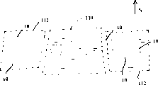
FIG. 10 is a schematic plan view of another aquaculture system constructed in accordance with the present invention;
FIG. 11 is a schematic plan view of yet another aquaculture system made in accordance with the present invention;
FIG. 12 is a partial cross-sectional view, similar to the drawings, of a strip of another artificial grass grid made in accordance with the present invention;
FIG. 13 is a partial cross-sectional view, similar to FIG. 3, of a strip of yet another artificial waterweed grid made in accordance with the present invention;
referring now to the drawings, in which like elements are represented by like reference numerals. Fig. 1 shows a plurality of artificial waterweed grids 10 made in accordance with the present invention. The float grass grid 10 can be used in seawater, freshwater, and other aquatic systems and environments. Each aquatic fence 10 has a plurality of ribbons 12 and a flexible anchor structure 14 to secure the ribbons 12 to the water bed 16 (fig. 2). The upper end of the ribbon 12 is suspended in the lighted area 18 by buoyancy.
In the illustrated embodiment, each aquatic weed grid 10 is constructed from a single sheet of multi-layer material that is folded and sewn (stitches 20) to form a hollow tube 22. The hollow tube 22 is located at the bottom of the folded sheet structure. The length of the sheet structure may be 10 meters, thereby forming a waterweed grid 10 measuring 10 meters long along the anchor structure. The sheet structure was cut longitudinally at 2.5 cm intervals in a direction perpendicular to its length to form individual ribbons 12.
The anchor structure 14 is formed by filling the hollow tube 22 with ballast 24. Ballast 24 may be sand, gravel, or other available material. Ballast 24 provides sufficient settling force to allow the float grass grid 10 to settle. The integral anchor structure 14 has the advantage that it does not need to be deep into the water bottom 16. Another advantage is that the flexible structure 14 allows the waterweed grid 10 to be easily moved to the desired separation distance in a pond, tank or riverbed to maximize shelter or to be removed for cleaning.
The length of the belt 12 may be determined according to the depth of the illuminated area 18 at the location where it is installed. While the illumination zone 18 may be 30 meters deep, a typical ribbon length may be 1 to 4 meters. In the illustrated embodiment, the ribbons 12 are each about 1.3 meters in length. Some belts may be longer than others to control shadowing and predation. As discussed in more detail below, the waterweed grids 10 may be arranged in rows at about 5 to 15 cm intervals.
The width and stiffness of the ribbons 12 can affect the mass transfer of nutrients between adjacent ribbons 12. The width and stiffness of the ribbon 12 can also affect the ability of the float grass grid 10 to provide shelter to aquatic life. The preferred height to width ratio of each ribbon 12 is in the range of 20: 1 to 60: 1. The width of the ribbon 12 may be from 1 cm to 5 cm, preferably 2.5 cm. The stiffness of each ribbon is 0.5 to 3.0 grams/cm as measured by ASTM D5342. Providing a buoyant material along the entire length of the ribbon 12 increases the stiffness of the ribbon 12.
In practice, the ribbons 12 move in the water in an undulating manner independently of each other. This wave motion helps the nutrient material to move toward or away from the surface of the belt 12. Although only two belts 12 are shown in fig. 2 for clarity, other belts 12 behind the belts shown are in fact visible.
Referring now to fig. 3, in the embodiment shown,each ribbon 12 has a first layer 30 and a second layer 32. The layers 30 and 32 are integrally bonded together by a suitable extrusion adhesive 34. The first layer 30 provides buoyancy. The second layer 32 provides a high surface area structure for increased aquatic growth. Layers 30 and 32 are generally coextensive with ribbon 12. In other words, each layer 30 and 32 extends substantially along the entire length and width of the ribbon 12.
In the embodiment shown, the first layer 30 is comprised of closed cell polyethylene foam about 2.2 millimeters thick. The first layer 30 may be transparent in order to allow light to be transmitted to the second layer 32.
In another embodiment, the closed cell foam material of the first layer 30 may be made of polyurethane, polypropylene, or other suitable material. The foam may have a specific weight of 0.05 to 0.6 g/cc, preferably 0.15 to 0.2 g/cc, and more preferably about 0.19 g/cc. Preferably, the specific gravity of the entire composite tape structure 30, 32, 34 is 0.15-0.25 g/cc.
The second layer 32 is comprised of an open cell polyethylene foam material. The open-cell foam material has a reticulated open-cell surface structure to support and thereby promote biological growth. The open-cell material provides a locus for aquatic periphyton attachment. To enhance algae growth, the cell size of the open cell structure should preferably be greater than about 20 microns and less than about 2000 microns. In the embodiment shown, the average pore size of the second layer 32 is about 200 microns.
The surface area of the open cell material used in the second layer 32 may be at least about 1.9 square meters per gram, and preferably greater than 20.0 square meters per gram.
Preferably, the second layer 32 is thin enough to allow mass transfer of nutrients through the surface structure. In the illustrated embodiment, the thickness of the second layer 32 is about 1.0+/-0.2 millimeters.
Preferably, the man-made structures 30, 32 and 34 are made of a material that can be sterilized by steam or chlorine without damage.
Figure 4 shows another artificial waterweed grid strip 40. The ribbon 40 has two second layers 32 sandwiching a buoyant layer 30. The ribbon 40 provides a greater surface area for increased biological growth. The ribbon 40 may be used in a waterweed grid as shown in figures 1 and 2.
Typically, it is advantageous to provide only one second layer 32 per ribbon (as is the case in fig. 3) to prevent the second layer from obscuring the other layers. However, in another embodiment of the invention, each ribbon may have 3 or more layers, with all layers being coextensive with each other.
Figure 5 shows another artificial waterweed grid strip 50. The ribbon 50 has a second layer 52 of spun polyester batt. The flocculent material provides a robust surface for increased biological growth. The belt 50 shown in fig. 5 is substantially identical to the belt 12 shown in fig. 1-3, except for the second layer 52. The belts 50 may be used in place of or in conjunction with the apertured belts 12 in a waterweed grid as shown in figures 1 and 2. In addition, the polyester batting material 52 may also be sandwiched over the buoyant layer 30 in the manner shown in FIG. 4.
In the embodiment shown in fig. 5, the polyester batting preferably has a weight in the range of 15 to 100 grams per square meter and provides a surface area of 1 to 100 square meters per gram, preferably less than 50 square meters per gram. Continuous filaments for making a composite three-dimensional batt structure have a diameter of 0.05 to 0.50 mm. In the illustrated embodiment, the batting material is SYNTECH 250 brand spun (spun) polyester batting manufactured by Synthetic Industries, inc, which is a 70 gram per square meter batt of spun polyester fibers and has a surface area of 24 square meters per gram.
In another embodiment of the present invention, the second layer 52 may be made of a dense felt. In another embodiment of the present invention, second layer 52 may be made of a highly lofted spunbond material. The present invention is not limited to the specific aquatic structures shown and described herein.
Fig. 6 shows a strip 60 of yet another artificial water grass structure. The ribbon 60 has a second layer 62, and the second layer 62 has a microporous surface structure. The ribbon 60 shown in fig. 6 is substantially the same as the ribbon 12 shown in fig. 1-3, except for the second layer 62. The belts 60 may be used in place of or in conjunction with the apertured belts 12 in a waterweed grid as shown in figures 1 and 2. In addition, the microporous layer 62 may also be used in a sandwich configuration on both sides of the buoyant material 30 in the manner shown in FIG. 4.
In the embodiment shown in FIG. 6, the second layer 62 preferably includes apertures 64 (FIG. 7) that are too small to allow the growth of typical periphyton algae. Thus, the predominant growth in the pores of microporous layer 62 will be limited to micro-plankton (picoplankkton), which is primarily bacterial in nature.
For bacteria that are desirable for a particular use (e.g., a clean environment), the growth of micro-plankton can be selectively enhanced by placing appropriate nutrients in apertures 64. Thus, the artificial grass grid can be tailored to one or more specific uses by pre-selecting the desired high surface area structure and/or providing selected nutrients in the pores 64 of the high surface area structure. In another embodiment of the invention, selected bacteria are injected into the pores 64 of the high surface area structure with or without nutrients infused into the porous structure.
In a preferred embodiment of the invention, an array of belts 60 can be used, wherein each belt has a different selected nutrient, thereby forming an artificial wetland (wetland) to remove and complex away excess nitrate and phosphorous-containing compounds from the water supply.
Very small holes 64 may be formed: multiple layers of particulate high surface area particles 66 (fig. 6) are bonded to the closed cell foam 30. The surface area of the particulate particles 66 may be in the range of 50 to 600 square meters per gram. The size of the particles 66 may be from 20 to 200 microns. The particles 66 may be made of carbon, silica, polyurethane, styrene-divinylbenzene copolymer, or other materials. The surface area and pore size of the particles 66 may be controlled during the process of manufacturing the particles 66 using known techniques. The present invention provides 100 or more times greater surface area available than natural plants while performing many other desirable functions of plants in aquatic environments, such as providing protection from predation.
Fig. 12 shows a ribbon 120 in yet another aquatic weed structure. The belt 120 has a second layer 122 made of a coarse open cell foam or high loft spunbond material. The belt 120 also has a third layer 124 made of open cell foam or dense felt. A buoyant layer 30, made of closed cell foam material, is sandwiched between the second layer 122 and the third layer 124. The three layers 30, 122 and 124 are bonded to each other and laminated together. Preferably, the third layer 124 is thicker than the second layer 122.
Preferably, the density of the third layer 124 is at least about 1.5 ounces per square yard. A felt material lighter than 1.5 ounces per square yard may allow for proper infusion so that oxygen enters all the channels, passes through the third layer124, and reaches the surface of the buoyant layer 30. In this way, even after the biofilm is established, the possibility of growth of facultative anaerobic microorganisms near the surface of the buoyant layer 30 can be eliminated.
Fig. 13 shows a further aquatic weed structured belt 130. Ribbon 130 has a second layer 132 and a third layer 134. The buoyant, closed cell foam layer 30 is located between the second layer 132 and the third layer 134. Second layer 132 and third layer 134 are formed by needle punched threads 136 that are used to pass back through buoyant layer 30. Preferably, the thickness of the third layer 134 is greater than the thickness of the second layer 132. The third layer 134 may be, for example, about 0.040 inches thick. The thickness of the second layer 132 can be less than about 0.016 inches. In addition, the permeability and diffusivity of the second layer 132 is preferably greater than the permeability and diffusivity of the third layer 134.
In the embodiment shown, the buoyant layer 30 has a thickness of about 0.095 inches. The second layer 132 and the third layer 134 are provided with a thread 136 of about 5 denier and an overall density of about 4 ounces per square yard. The distribution of lines 136 on the second layer 132 and the third layer 134 is about 30% and 70%, respectively.
The third layer 134 may have a thickness of about 0.042 inches and a load of 10 grams per square centimeter. The thickness of the second layer 132 is preferably about 0.016 inches. The permeability of third layer 134 at the surface of foam layer 30 is about 0.23 darcy. The permeability of the second layer 132 at the surface of the foam layer 30 is about 31 darcy. Without limiting the scope of the invention, the total surface area of the aquatic weed structure 130 may be about 564 square meters per square meter of surface, with a lower limit of 40 angstroms for all holes being considered.
While the particular embodiment shown in FIG. 13 provides good results, the present invention is not limited to the particular structures described and illustrated in detail herein.
The aquatic structures shown in figures 12 and 13 can promote both aerobic and facultative anaerobic reactions in close proximity to each other. Specifically, the aerobic reduction of ammonia may occur very rapidly within second layers 122 and 132, near the surface of buoyant layer 30, as long as structures 120 and 130 are located in water having a dissolved oxygen content of 2 to 12 milligrams per liter. The chemical formula of the ammonia reduction reaction is as follows:
meanwhile, anaerobic reduction reactions of nitrates may occur in the third layers 124 and 134, near the surface of the buoyant layer 30. Peroxidase surface analysis shows that nitrate reduction reactions can be limited to regions deeper within the thicker third layers 124 and 134.
Thus, for example, a third layer 134 of needle felt having a density of at least about 1.5 ounces per square yard and having established a biofilm and debris (detritus) layer may be used to prevent dissolved oxygen from reaching the surface of the buoyant layer 30, thereby creating a sufficiently anaerobic environment to support the growth of the genus Nitrobacter (Nitrobacter), the main genus involved in the nitrite/nitrate reduction reaction.
In addition, density profiling of the third layers 124 and 134 using porosimetry (posimetric) has shown that the permeability or diffusivity of the third layers 124 and 134 is another way to describe their effect on oxygen transport limitation. The size of the pores in the third layers 124 and 134 and the relative thickness of the third layers 124 and 134 both affect permeability.
At the surface of the buoyant layer 30, the third layers 124 and 134 have a water diffusivity less than DAB=1×10⁻⁶The square centimeter per second generally results in an oxygen mass transfer rate through the third layers 124 and 134 that is sufficiently low to allow an anaerobic environment to be established. The addition of a layer of bacterial debris in the pore structure of the third layers 124 and 134 may further reduce permeability and thus diffusivity.
The more open structure of the second layers 122, 132 allows mass transfer of oxygen to be limited only by this gas concentration gradient in the water. Oxygen utilization is limited to aerobic decomposition of solutes transported by diffusion in water by bacteria. The diffusion rate of gases in fluids is typically an order of magnitude higher than the diffusion rate of inorganic solutes (nitrates and nitrites).
Furthermore, the closely associated periphyton layer on the outermost surface of second layers 122, 132 generates oxygen in the sun, thereby increasing the local gradient of oxygen saturation near second layers 122, 132.
The two aforementioned diffusion phenomena, controlled by the permeability of the aquatic weed structures 120, 130, allow aerobic and anaerobic processes to be performed simultaneously, separated by only a few microns. Thus, the aquatic weed structures 120, 130 have greatly improved biofilter performance. With the present invention, water contaminated with high concentrations of nitrate, nitrite and ammonia can be treated with a single filter type at very high mass transfer rates. Thus, for example, the invention is particularly useful for treating farm run-off in constructed wetlands.
The combination of the very short mass transfer distance with the use of a thin membrane and the availability of high concentrations of dissolved oxygen produced by aquatic epiphytic algae colonies in photosynthesis can very quickly convert the dissolved inorganic nutrients (nitrate, nitrite and ammonia) into biological tissue. These biological tissues can be used as food sources for aquatic organisms such as Finnish aquaria (Finnish), crustaceans, mollusks, and the like. While producing aquatic periphyton, the toxicity caused by dissolved inorganic compounds, particularly ammonia, can be reduced, thereby increasing the stocking density of many species that cannot survive even at ordinary concentrations of ammonia. Examples of species that benefit greatly from ammonia removal are shrimp, bass, trout and salmon.
The material used for the ribbons 12, 40, 50, 60, 120, 130 is preferably composed of a polymer that does not release harmful chemicals into the environment. The material of the ribbons 12, 40, 50, 60, 120, 130 should not degrade in water (including seawater) and sunlight. Therefore, the waterweed fence 10 can be used for a long period of time and can be cleaned and reused elsewhere. If desired, the ribbons 12, 40, 50, 60, 120, 130 may contain one or more additional layers (not shown) or substances to reinforce, preserve, or protect the ribbons 12, 40, 50, 60, 120, 130.
Referring now to fig. 8, an artificial waterweed grid 70 has a ribbon 72 with a buoyant structure 74 secured at the upper end. Ribbon 72 may be the same as ribbons 12, 40, 50, 60, 120, 130 described above, in which case ribbon 72 is buoyant and buoyancy structure 74 provides additional buoyancy. Alternatively, the ribbons 72 may be constructed primarily or entirely of one or more of the above-described high surface area structural materials 32, 52, 62, 122, 124, 132, 134, with the buoyancy structure 74 providing all or most of the buoyancy required to support the ribbons 72.
The buoyant structure 74 may be made of open cell polyethylene foam or other suitable buoyant material. The buoyant structure 74 may be adhered, sewn or otherwise suitably attached to the upper end of the ribbon 72. As with the other embodiments described above, the aquatic weed grid 70 may be used to enhance the growth of living organisms and provide a shelter in the water.
Referring now to fig. 9, the artificial waterweed grid 10 shown in fig. 1 and 2 is arranged in a spiral or other substantially closed manner to serve as a shelter or boom 100 for a scallop, clam shell, oyster or other mollusk. The boom 100 is particularly suitable for collecting and feeding young oysters. The same length of the waterweed grid can be used to form the boom 100 of different inside diameters 104, 106 by making the spiral slightly tighter or looser as desired.
In operation, a scallop (not shown) may be placed in the center 102 of the boom 100. When young oysters (larvae) begin to shell, they migrate radially outward from the center 102. The young oysters in growth are attached to the strips 12 of the waterweed grid 10. During the growth cycle, the waterweed grid 10 will attract and promote the production of food in the vicinity of fast growing young scallops.
After the young oysters are secured, the aquatic fencing 10 can be isolated and distributed to the location of the maturation process where the perimeter fencing of the aquatic fencing 10 prevents scallops from escaping. In one embodiment of the invention, ballast 24 may be poured from the flexible anchor structure 14, causing the anchor structure 14 to expand and float the waterweed grid to the surface.
Thus, in the present invention, a mobile structure is used to provide a food source, a shelter against predation, and a holder for harvesting of the growing organisms, and to facilitate the enhanced recovery and growth of young oysters.
As shown in FIG. 10, the artificial waterweed grids made accordingto the present invention can be arranged parallel to each other or in a staggered manner to accommodate the growth of a finned aquarium over a wide range. In the area 110, all the waterweed grids 10 are close to each other, providing shade and maximum protection against predation for the young fish. In the offset or spaced areas 112, more open area (less coverage) is provided for larger fish. In addition, the spacer region 112 provides more opportunity for exposure to photosynthesis, thereby improving food production. The waterweed fence 10 may be arranged in an east-west direction (perpendicular to the north direction) to maximize exposure to sunlight during the middle of the day. The underwater topography is a consideration in determining the required separation distance of the float grass grid 10.
Fig. 11 shows a plan layout of another flexible waterweed grid 10. As shown, the ends 118 of the artificial waterweed fence 10 may overlap to form an anti-predation area 128. In areas where there is no overlap, more sunlight can be utilized, thereby enhancing the growth of aquatic periphytons. The amount of linear overlap of the waterweed grid ends 118 can be determined as a function of the amount of shading, the degree of predation control required, the type of aquatic organisms to be farmed, and other parameters.
In fig. 9-11, the float grass grid 10 is shown schematically by line segments for clarity only. In practice, the undulations of the aquatic ribbons 12 cause the aquatic grill 10 to have a non-uniform, constantly changing profile in plan view. Depending on the degree of movement in the water, the belts 12 will undulate past each other and slide past each other, which will promote mass transfer between the aquatic grass grid 10 and the water, and the belts 12 and the water.
Example I
120 artificial grass grids 10 are arranged in a series of fresh water ponds of average depth 130 cm, the grass grids 10 being spaced 5 cm apart and each row having 60 strips. There are 30 pasture and water grids per hectare. Zooplankton production in these ponds was 7-20 times greater than in control ponds without artificial pasture grids. After 52 days of initial growth, the large eyes were raised in the pool of Seriola quinqueradiata (Walleye) 18% greater than in the control pool. The survival rate was not statistically different between the control ponds and the ponds with 30 waterweed grids/hectare in the first 52 days, but during the 0-92 days the fish not only gained 31.8% weight, but also the survival rate in the ponds with waterweed grids was 80% compared to 64% for the control ponds. Combining these two factors (weight and survival rate) means that the total biomass production is 84% higher in 30 waterweed grids/hectare ponds than in the control pond. The yield is increased, and meanwhile, the utilization rate of the fertilizer is reduced by 78%, so that the production cost is reduced by 12%.
Example II
An artificial water grass bed having the composite strip structure shown in fig. 5 was placed in a fresh water pool. Each bed had 400 strips/wire grid (or rows of strips). The spacing between the waterweed grids is about 7.5 centimeters. The ribbon is about 2.5 cm wide and 100 cm long. The survival rate of micropterus salmoides grown in the artificial structure was 2.3 times that of the fish in the control pond without the structure, and the fish was 43.5% larger in the pond with the artificial turf. Zooplankton production in the pool with the artificial structure was 12 times higher than in the control pool. The effective fish population that can be supported in a pool with artificial structures can be increased by 250%.
Example III
The artificial water grass bed having the composite strip structure shown in fig. 6 was arranged in rows in which the strips were about 2.5 cm wide and 45 cm long. Each row has 24 strips. There are 20 rows per bed. The spacing between rows is about 5.0 cm. The second layer of each ribbon was composed of a coating of porous silica particles having an average particle size of 40 microns, a surface area of 360 square meters per gram and an average pore diameter of 80 angstroms. The bed was submerged in 45 cm of water.
The simulated wastewater effluent was pumped through the submerged bed at an average linear velocity of 30 mm/min. The water was spiked with nitrate (100 mg nitrate/l) and phosphate (5 mg/l). After establishing the bacterial population at 12 days of estimated digestion, it was found that 92% nitrate and 76% phosphate were removed from the solution in consecutive cases. Compared to the typical water retention time (HRT) of a conventional sponge biofilter, the artificial turf bed arranged and used in an artificial wetland manner was 90 Times faster than the conventional filter technology with the same HRT.
Example IV-Bioaccumulation
The artificial water grass bed with the composite ribbon structure shown in fig. 6 was arranged in rows with the ribbons about 2.5 cm wide and 25 cm long. There are 24 strips per row and 48 rows per bed. The spacing between rows is about 5 cm. The first layer of each ribbon is composed of a buoyant polyethylene foam having a specific gravity of about 0.12. The second layer of each ribbon was composed of a coating of porous silica particles having an average particle size of 60 microns, a surface area of 280 square meters per gram and an average pore diameter of 120 angstroms.
The bed was submerged in 25 cm of water. The simulated electroplating bath solution was pumped through the submerged bed at an average linear speed of 50 mm/min. The bed was placed in a solution containing conventional nutrient broth (Difco B3+ iron), 100 grams of soil fromthe acidic mineral effluent field, and injected diffusion air at a flow rate sufficient to maintain a dissolved oxygen concentration above 10 mg/l. After 10 days, the bath was drained and a simulated electroplating bath wastewater solution (pH 3.0) containing 100ppm6+ chromium and 100ppm2+ zinc was pumped through the bed at an average linear speed of 25 mm/min. After passing 185 liters (1 bed volume) through the bed, the effluent was measured and the residual concentrations of chromium and zinc were found to be 1.1ppm and 2.3ppm, respectively.
To determine the load capacity of the system, the simulated plating bath solution was pumped through the system in 50 liters batches until the heavy metal concentration in the effluent was 5% of the input solution. The chromium and zinc loadings were 17,850 and 13,670 litres respectively. Based on the dry weight recovery recovered, it was found that the biological growth on the surface of the strip may contain 7.5-11% by weight of heavy metals, which are complexed and thus prevented from being bioavailable in the future. This indicates an enrichment capacity of 1100 times.
Immobilized metals associated with the bioaccumulation process can be removed from the flexible ribbons by acid exchange. Alternatively, fibrous waterweed grids can be incinerated to recover toxic species of metals. Compared with ion exchange technology, the present invention has load capacity of at least 12 times and treating speed of 10 times, and can change the valence state of metal to reduce its biological toxicity.
After acid extraction with phosphoric acid at pH1.8, the artificial aquatic weed material was resuspended in the starting broth for 12 days and then subjected to the test. After an equilibration period and a flow rate of 10 mm/min through the first bed volume of the resultant electroplating bath mixture, the concentrations of 0.08ppm of 6+ valent chromium and 0.13ppm of zinc in the effluent were found.
Thus, continuous reuse and greater conditioning of the bio-accumulation system is observed, which can increase its relative efficiency and capacity. It was determined that at a linear velocity of 15 mm/min, optimal mass transfer occurred with bio-accumulation. The maximum load is related to the quality of biological growth in the microporous structure of the ribbon. In these tests, the maximum concentration ratio achieved for chromium was 1,870 to 1. The maximum load achieved can be extracted from the 6+ valence state by 2.15 grams of chromium on a single artificial waterweed grid. During 5 runs, the biomass grown on the total surface area of the waterweed grids was 21.47 grams (dry weight) and the chromium loading was 2.278 grams, i.e., 10.61%.
Example V
The aquatic weed structure as shown in fig. 13 was placed in a fish raceway (street) and aged for 2 months to establish a suitable biofilm on various surfaces. The structure was then placed in a 3 cubic meter container at a ratio of 10 square meters per cubic meter of water. Ammonia and sodium nitrate were added to the container so that their concentrations were 5 mg/l and 200 mg/l, respectively. In about 6 hours, the structure removed 90% of the ammonia and in about 10.5 hours, the structure removed about 90% of the nitrate.
The above description and drawings are only illustrative of the preferred embodiments which achieve and provide the objects, features and advantages of the present invention. The present invention is not limited to the embodiments described and shown in detail herein. Modifications that fall within the scope and spirit of the claims are to be considered part of the invention.
Claims (29)
1. An artificial aquatic plant structure forsimultaneously providing food, predation shelter and breeding environment for biological species, comprising:
a plurality of ribbons; and
an anchor structure for anchoring the strip to the water bottom; and
wherein each ribbon comprises: (A) a buoyant layer for extending the ribbon upwardly in the lighted area; and (B) a second biological growth enhancing layer configured, the second layer comprising high surface area structures that promote biological growth on the ribbon, and the high surface area structures of the second layer having a surface area greater than or equal to 1 square meter per gram.
2. The artificial waterweed structure of claim 1 wherein the ribbons are arranged in rows.
3. The artificial waterweed structure of claim 2 wherein the strips are spaced apart to enhance photosynthesis.
4. The artificial waterweed structure of claim 2, wherein the rows are spaced at intervals of about 5-15 centimeters.
5. The artificial waterweed structure of claim 1, wherein the buoyant layer comprises a closed cell foam of polymer plastic.
6. The artificial waterweed structure of claim 5, wherein the closed cell foam comprises polyethylene.
7. The artificial waterweed structure of claim 5, wherein the closed cell foam comprises polyurethane.
8. The artificial waterweed structure of claim 5 wherein the closed cell foam comprises polypropylene.
9. The artificial aquatic grass structure of claim 5 wherein said second layer comprises an open cell foam material, wherein the cell size is from about 20 microns to about 200 microns.
10. The artificial aquatic weed structure of claim 5, wherein the second layer comprises a porous particulate material adhered to the buoyant layer.
11. The artificial waterweed structure of claim 10, further comprising nutrients for enhancing algae growth, at least some of which are located in the porous particulate material.
12. The artificial waterweed structure of claim 10, further comprising nutrients for enhancing bacterial growth, at least some of which are located in the porous particulate material.
13. The artificial waterweed structure of claim 10, further comprising nutrients for enhancing microbial growth for a clean environment, and at least some of said nutrients are located in said porous particulate material.
14. The artificial waterweed structure of claim 10, further comprising microbes embedded in the high surface area structure.
15. The artificial waterweed structure of claim 14, wherein the microorganisms comprise bacteria.
16. An artificial aquatic plant structure for simultaneously providing food, predation shelter and breeding environment for biological species, comprising:
a plurality of ribbons; and
an anchor structure for anchoring the strip to the water bottom; and
wherein each ribbon comprises: (A) a buoyant layer for extending the ribbon upwardly in the lighted area; and (B) a second biological growth enhancing layer configured, the second layer comprising a high surface area structure that promotes biological growth on the ribbon, and the ribbon having a stiffness of 0.5 to 3.0 grams per centimeter.
17. The artificial waterweed structure of claim 16 wherein the ribbons are 1-5 cm wide and 1-4 meters long.
18. The artificial waterweed structure of claim 17, wherein the second layer comprises elongated filaments that form a composite three-dimensional batt structure having a surface area of 1-100 m/g.
19. The artificial waterweed structure of claim 17 wherein the anchor structure comprises a hollow tube of multiple layers of material, wherein the tube is filled with ballast.
20. The artificial waterweed structure of claim 19 wherein the tube and the ribbon are formed from a single piece of material and the ballast comprises a granular material.
21. An artificial aquatic plant structure for simultaneously providing food, predation shelter and breeding environment for biological species, comprising:
a plurality of ribbons; and
an anchor structure for anchoring the strip to the water bottom; and
wherein each ribbon comprises: (A) a buoyant layer for extending the ribbon upwardly in the lighted area; and (B) a second layer of construction to enhance biological growth, the second layer comprising a high surface area structure to promote biological growth on the ribbon, and the buoyant layer and the second layer forming a multilayer structure having a specific gravity of less than or equal to 0.25 grams per cubic centimeter.
22. The artificial waterweed structure of claim 21, wherein the buoyant layer has a specific gravity of less than or equal to 0.6 grams per cubic centimeter.
23. The artificial waterweed structure of claim 21 wherein the buoyant layer has a specific gravity of about 0.05-0.6 g/cc.
24. An artificial structure, characterized in that it comprises:
a buoyant material; and
first and second high surface area structures that simultaneously promote aerobic and anaerobic reactions in the water, the buoyant material being positioned between the first and second high surface area structures, and the first and second high surface structures being formed of a different material, the second high surface structure being formed of a different material than the buoyant material, and the first and second high surface structures having a surface area greater than or equal to 1 square meter per gram.
25. The artificial structure of claim 24 wherein the first high surface area structure comprises a coarse open cell foam.
26. The artificial structure of claim 24 wherein the first high surface area structure comprises a highly extensible spunbond material.
27. The man-made structure of claim 24,wherein the second high surface area structure comprises open cell foam.
28. The artificial structure of claim 24 wherein the second high surface area structure comprises a dense felt.
29. The artificial structure of claim 24 wherein the first and second high surface area structures are formed by needling lines through the buoyant material and the second high surface area structure has a thickness greater than the thickness of the first high surface area structure.
Applications Claiming Priority (4)
| Application Number | Priority Date | Filing Date | Title |
|---|---|---|---|
| US08/943,335 US6060153A (en) | 1997-10-03 | 1997-10-03 | Synthetic aquatic structure |
| US08/943,335 | 1997-10-03 | ||
| US09/041,671 | 1998-03-13 | ||
| US09/041,671 US6171686B1 (en) | 1997-10-03 | 1998-03-13 | Synthetic aquatic structure |
Publications (2)
| Publication Number | Publication Date |
|---|---|
| CN1213725A CN1213725A (en) | 1999-04-14 |
| CN1105809C true CN1105809C (en) | 2003-04-16 |
Family
ID=26718394
Family Applications (1)
| Application Number | Title | Priority Date | Filing Date |
|---|---|---|---|
| CN98106999A Expired - Fee Related CN1105809C (en) | 1997-10-03 | 1998-04-16 | Synthetic aouatic structure |
Country Status (4)
| Country | Link |
|---|---|
| US (1) | US6230654B1 (en) |
| KR (1) | KR19990036465A (en) |
| CN (1) | CN1105809C (en) |
| AU (1) | AU758271B2 (en) |
Families Citing this family (27)
| Publication number | Priority date | Publication date | Assignee | Title |
|---|---|---|---|---|
| US6060153A (en) * | 1997-10-03 | 2000-05-09 | Marine Environmental Solutions, L.L.C. | Synthetic aquatic structure |
| US20020022426A1 (en) * | 1999-12-21 | 2002-02-21 | The Procter & Gamble Company | Applications for elastic laminate web |
| US6834617B1 (en) * | 2003-09-08 | 2004-12-28 | Suzhou Good View Aquaria Technology Co., Ltd. | Aquarium background setting |
| US7512326B1 (en) | 2005-04-06 | 2009-03-31 | Eldredge John T | Artificial foliage for underwater camouflage and decoy purposes |
| US7392765B2 (en) * | 2006-01-18 | 2008-07-01 | Terry R. Lingmann | Biodegradable pet mat |
| US7544286B2 (en) * | 2006-05-16 | 2009-06-09 | Environmental Dynamics, Inc. | Method and apparatus for enhancing aquatic environments |
| US8042491B2 (en) * | 2006-10-13 | 2011-10-25 | David Joseph Fulbrook | Weedless fish structure |
| CN100528772C (en) * | 2007-10-25 | 2009-08-19 | 中国科学院南京地理与湖泊研究所 | Method for removing settled organism on surface of submerged plant by using grazer |
| US7836853B2 (en) * | 2007-11-06 | 2010-11-23 | Mary Elizabeth Locklear | Aquarium bottom surface substrate |
| US8092606B2 (en) * | 2007-12-18 | 2012-01-10 | Asm Genitech Korea Ltd. | Deposition apparatus |
| CN101254975B (en) * | 2008-04-02 | 2010-06-02 | 国家环境保护总局华南环境科学研究所 | Method for manufacturing artificial float grass and uses thereof |
| US20120279109A1 (en) * | 2011-05-05 | 2012-11-08 | Nichol David J | Artificial Weed System for Ice Fishing |
| US20110219663A1 (en) * | 2011-05-05 | 2011-09-15 | Nichol David J | Artificial Weed System for Fishing |
| CN102440208A (en) * | 2011-10-10 | 2012-05-09 | 中国水产科学研究院淡水渔业研究中心 | A kind of artificial shrimp nest of freshwater shrimp |
| CN103290806B (en) * | 2012-10-29 | 2015-08-26 | 中国长江三峡集团公司 | Environmentally friendly ecological bank protection system |
| US20160031723A1 (en) * | 2014-07-30 | 2016-02-04 | Sei Manufacturing, Inc. | Water filtration devices and methods |
| US20160242396A1 (en) * | 2015-02-20 | 2016-08-25 | Current-Usa, Inc. | Aquascaping system |
| CN104695381B (en) * | 2015-03-05 | 2016-03-02 | 黄河勘测规划设计有限公司 | Rivers bank slope imitates pasture and water energy dissipating safeguard structure |
| CN105113458A (en) * | 2015-09-14 | 2015-12-02 | 李万青 | Method for reducing scouring erosion of turbulent flow in water flow to bottom or side walls of river ditch in water conservancy project |
| CN105155466A (en) * | 2015-09-14 | 2015-12-16 | 李万青 | Method for reducing washout erosion to bottom or side wall of barrage ditch caused by turbulence in water flow in hydraulic engineering |
| AU2016100350B4 (en) * | 2016-04-01 | 2016-07-28 | Stuart John Thomson | Method and device for reducing sand erosion |
| US11751544B2 (en) * | 2018-11-01 | 2023-09-12 | Edem Tsikata | Cavitation barrier for aquatic species |
| CN110589981B (en) * | 2019-10-15 | 2024-06-07 | 上源环工生态环境科技(苏州)有限公司 | Combined three-dimensional ecological floating bed for riverway restoration and purification |
| CN111109177B (en) * | 2019-12-29 | 2022-04-01 | 南京瀚邦生态农业科技有限公司 | Aquatic microorganism water purification and shelling culture system and process |
| CN111955392B (en) * | 2020-07-28 | 2022-03-22 | 河海大学 | Breeding method for improving specifications of hairy crabs by adopting soil improvement |
| US20220087232A1 (en) * | 2020-09-21 | 2022-03-24 | Th Products, Llc | Fish attracting systems and methods |
| USD1081905S1 (en) * | 2021-11-05 | 2025-07-01 | Th Products, Llc | Fish habitat brace |
Family Cites Families (42)
| Publication number | Priority date | Publication date | Assignee | Title |
|---|---|---|---|---|
| DK104835C (en) | 1963-01-14 | 1966-07-04 | Roblon As | Means for regulating or influencing material migration under water. |
| GB1162419A (en) | 1967-12-01 | 1969-08-27 | Shell Int Research | Artificial Seaweed |
| GB1176772A (en) | 1968-04-24 | 1970-01-07 | Shell Int Research | A Seaweed Substitute. |
| US3590585A (en) | 1968-04-24 | 1971-07-06 | Shell Oil Co | Composite structure |
| US3562952A (en) * | 1968-07-22 | 1971-02-16 | Pietro O Bramante | Plant anchor |
| US3559407A (en) | 1968-11-25 | 1971-02-02 | Shell Oil Co | Artificial seaweed |
| US3540415A (en) | 1969-04-18 | 1970-11-17 | James E Bromley | Synthetic reef ecological system for large bodies of water |
| US3744454A (en) * | 1971-06-04 | 1973-07-10 | Metaframe Corp | Rock and gravel bed simulation for aquariums |
| JPS4946760B2 (en) | 1972-03-06 | 1974-12-11 | ||
| GB1385974A (en) | 1972-04-18 | 1975-03-05 | Shell Int Research | Method of and apparatus for producing artificial seaweed |
| US3820339A (en) | 1973-04-09 | 1974-06-28 | Shell Oil Co | Artificial seaweed cut from continuous band |
| JPS5470989A (en) | 1977-11-11 | 1979-06-07 | Nippon Synthetic Chem Ind | Artificial algae |
| US4221078A (en) * | 1978-09-27 | 1980-09-09 | Latham John F | Sealed globular display device |
| US4374629A (en) * | 1979-01-26 | 1983-02-22 | Garrett William L | Synthetic seaweed |
| US4221500A (en) | 1979-01-26 | 1980-09-09 | Garrett William L | Synthetic seaweed |
| US4478533A (en) | 1979-01-26 | 1984-10-23 | Garrett William L | Synthetic seaweed |
| EP0018082B1 (en) * | 1979-04-24 | 1982-10-27 | Imperial Chemical Industries Plc | Underwater erosion control structure |
| US4312152A (en) * | 1980-06-09 | 1982-01-26 | Agrownautics, Inc. | Buoyant support structure and system and method using structure for water culture of plants |
| US4441453A (en) | 1982-02-10 | 1984-04-10 | Berkley And Company, Inc. | Artificial fish habitat |
| US4437786A (en) | 1982-07-06 | 1984-03-20 | Morrisroe John P | Artificial seaweed |
| US4641997A (en) | 1982-12-27 | 1987-02-10 | Lauer John F | Synthetic seaweed kit and synthetic seaweed matrix formed thereby |
| US4490071A (en) | 1983-01-21 | 1984-12-25 | Morrisroe John P | Artificial seaweed and method of accreting waterfronts |
| US4534675A (en) | 1983-09-26 | 1985-08-13 | Morrisroe John P | Artificial seaweed |
| GB8402361D0 (en) | 1984-01-30 | 1984-02-29 | Alsop Peter | Controlling erosion of sea/river beds |
| DE3403165A1 (en) | 1984-01-31 | 1985-08-01 | Fa. Joh. Moritz Rump, 5990 Altena | DEVICE FOR GROUND STABILIZATION IN WATER CONSTRUCTION |
| WO1987005642A1 (en) | 1986-03-18 | 1987-09-24 | Earthnics Corporation | Sheet for forming twisted surface and production thereof |
| US4699829A (en) | 1986-04-24 | 1987-10-13 | Willinger, Bros. Inc. | Biological filtration plants |
| US4950104A (en) | 1987-04-07 | 1990-08-21 | Rodolphe Streichenberger | Artificial substrates for marine biomass enhancement and wave energy absorption |
| GB8904170D0 (en) | 1989-02-23 | 1989-04-05 | Alsop Peter | Underwater soil retention structures |
| US5365884A (en) * | 1989-03-17 | 1994-11-22 | Jones Richard L | Ornamental assembly for use in non-aquatic viewing cages or the like |
| US5257596A (en) * | 1989-03-17 | 1993-11-02 | Jones Richard L | Ornamental assembly for use in aquariums or the like |
| US5113792A (en) | 1991-05-22 | 1992-05-19 | Jones Barton G | Artificial reef module |
| US5309672A (en) | 1992-10-05 | 1994-05-10 | Electric Power Research Institute, Inc. | Submerged platform structure for open ocean macroalgal farm systems |
| US5639657A (en) | 1993-03-30 | 1997-06-17 | Nippon Tetrapod Co., Ltd. | Process for formation of artificial seaweed bed |
| CA2121227C (en) * | 1993-04-14 | 2003-07-08 | Lawrence I. Wechsler | Article anchoring accessory for use with aquariums |
| JPH07307326A (en) | 1994-05-11 | 1995-11-21 | Sony Corp | Plasma etching apparatus and plasma etching method |
| US5575584A (en) | 1994-08-01 | 1996-11-19 | Marine Environmental Solutions, L.L.C. | Underwater soil erosion prevention system |
| US5669330A (en) | 1995-06-07 | 1997-09-23 | O'hare; Christopher F. | Aquatic organism habitat device |
| US5876151A (en) * | 1996-06-17 | 1999-03-02 | Marine Environmental Solutions, L.L.C. | Frame and method for installing viscous drag and non-laminar flow components of an underwater erosion control system |
| US5871303A (en) | 1996-06-17 | 1999-02-16 | Marine Environmental Solutions L.L.C. | Viscous drag and non-laminar flow component of underwater erosion control system |
| US6060153A (en) | 1997-10-03 | 2000-05-09 | Marine Environmental Solutions, L.L.C. | Synthetic aquatic structure |
| US6004635A (en) * | 1998-04-20 | 1999-12-21 | Li; Wing Hon | Artificial plant assembly |
-
1998
- 1998-03-30 AU AU59687/98A patent/AU758271B2/en not_active Ceased
- 1998-04-13 KR KR1019980013028A patent/KR19990036465A/en not_active Withdrawn
- 1998-04-16 CN CN98106999A patent/CN1105809C/en not_active Expired - Fee Related
- 1998-08-14 US US09/134,735 patent/US6230654B1/en not_active Expired - Fee Related
Also Published As
| Publication number | Publication date |
|---|---|
| AU5968798A (en) | 1999-04-22 |
| KR19990036465A (en) | 1999-05-25 |
| US6230654B1 (en) | 2001-05-15 |
| AU758271B2 (en) | 2003-03-20 |
| CN1213725A (en) | 1999-04-14 |
Similar Documents
| Publication | Publication Date | Title |
|---|---|---|
| CN1105809C (en) | Synthetic aouatic structure | |
| CN103391712B (en) | Multi-layer cultivation device for bivalve molluscs and cultivation method using the same | |
| CN102060383A (en) | Floating treatment streambed | |
| CN103332790A (en) | Light enhancing oxygen-enriched organism structural system for synchronously repairing eutrophicated water bodies in rivers and lakes and sediments in situ | |
| CN104129856A (en) | Combined ecological floating bed and culture method thereof | |
| US6060153A (en) | Synthetic aquatic structure | |
| MXPA00012318A (en) | Resin cultivating base, water purifying device and method using resin cultivating base. | |
| JPH11137117A (en) | Concrete block and seaweed reef for seaweed community development | |
| US6171686B1 (en) | Synthetic aquatic structure | |
| US6343567B1 (en) | Synthetic aquatic structure and method | |
| CN101274811B (en) | Decomposition and removal method of sediment in environmental water | |
| CN208038255U (en) | A kind of ecological canal of coastal tidal aquaculture source water treatment | |
| JP6480071B1 (en) | Aquaculture equipment | |
| JP3902476B2 (en) | Firefly successive breeding system and method | |
| CA2274054C (en) | Synthetic aquatic structure, method of controlling an aquatic environment, and aquarium | |
| JPH07274767A (en) | Fish preserve for culture | |
| CN2773062Y (en) | Biological float island frame | |
| CN209685413U (en) | A kind of ecological floating island purifier | |
| JPH07284355A (en) | Sea water-filtering device for fish culture preserve | |
| HK1019465A (en) | Synthetic aquatic structure | |
| KR200447660Y1 (en) | Non-return aquarium | |
| JP2006217895A (en) | Culturing method and culturing system for prawn | |
| JP2000246273A (en) | Zooplankton holding structure and water purification method using the same | |
| MXPA98002755A (en) | Sintet water structure | |
| CN111087079A (en) | Attached algae dominantly growing water body biological purification treatment device |
Legal Events
| Date | Code | Title | Description |
|---|---|---|---|
| C06 | Publication | ||
| PB01 | Publication | ||
| C10 | Entry into substantive examination | ||
| SE01 | Entry into force of request for substantive examination | ||
| C14 | Grant of patent or utility model | ||
| GR01 | Patent grant | ||
| REG | Reference to a national code |
Ref country code: HK Ref legal event code: WD Ref document number: 1019465 Country of ref document: HK |
|
| C17 | Cessation of patent right | ||
| CF01 | Termination of patent right due to non-payment of annual fee |
Granted publication date: 20030416 Termination date: 20120416 |