CN110683082A - Apple equipment for packing - Google Patents
Apple equipment for packing Download PDFInfo
- Publication number
- CN110683082A CN110683082A CN201911044193.XA CN201911044193A CN110683082A CN 110683082 A CN110683082 A CN 110683082A CN 201911044193 A CN201911044193 A CN 201911044193A CN 110683082 A CN110683082 A CN 110683082A
- Authority
- CN
- China
- Prior art keywords
- end wall
- face
- block
- rear end
- groove
- Prior art date
- Legal status (The legal status is an assumption and is not a legal conclusion. Google has not performed a legal analysis and makes no representation as to the accuracy of the status listed.)
- Withdrawn
Links
- 238000012856 packing Methods 0.000 title claims description 3
- 241000220225 Malus Species 0.000 claims abstract description 40
- 238000004806 packaging method and process Methods 0.000 claims abstract description 16
- 235000021016 apples Nutrition 0.000 claims abstract description 13
- 230000005540 biological transmission Effects 0.000 claims description 36
- 230000002146 bilateral effect Effects 0.000 claims description 4
- 230000006835 compression Effects 0.000 claims 1
- 238000007906 compression Methods 0.000 claims 1
- 235000005224 Eucalyptus bridgesiana Nutrition 0.000 abstract description 11
- 244000239638 Eucalyptus bridgesiana Species 0.000 abstract description 11
- 235000013399 edible fruits Nutrition 0.000 description 6
- 238000004519 manufacturing process Methods 0.000 description 2
- 230000009286 beneficial effect Effects 0.000 description 1
- 230000005484 gravity Effects 0.000 description 1
- 229910052500 inorganic mineral Inorganic materials 0.000 description 1
- 239000011707 mineral Substances 0.000 description 1
- 238000012986 modification Methods 0.000 description 1
- 230000004048 modification Effects 0.000 description 1
- 238000012858 packaging process Methods 0.000 description 1
- 230000000149 penetrating effect Effects 0.000 description 1
- 239000007858 starting material Substances 0.000 description 1
- 229940088594 vitamin Drugs 0.000 description 1
- 229930003231 vitamin Natural products 0.000 description 1
- 235000013343 vitamin Nutrition 0.000 description 1
- 239000011782 vitamin Substances 0.000 description 1
Images


Classifications
-
- B—PERFORMING OPERATIONS; TRANSPORTING
- B65—CONVEYING; PACKING; STORING; HANDLING THIN OR FILAMENTARY MATERIAL
- B65B—MACHINES, APPARATUS OR DEVICES FOR, OR METHODS OF, PACKAGING ARTICLES OR MATERIALS; UNPACKING
- B65B1/00—Packaging fluent solid material, e.g. powders, granular or loose fibrous material, loose masses of small articles, in individual containers or receptacles, e.g. bags, sacks, boxes, cartons, cans, or jars
- B65B1/04—Methods of, or means for, filling the material into the containers or receptacles
- B65B1/10—Methods of, or means for, filling the material into the containers or receptacles by rotary feeders
-
- B—PERFORMING OPERATIONS; TRANSPORTING
- B65—CONVEYING; PACKING; STORING; HANDLING THIN OR FILAMENTARY MATERIAL
- B65B—MACHINES, APPARATUS OR DEVICES FOR, OR METHODS OF, PACKAGING ARTICLES OR MATERIALS; UNPACKING
- B65B1/00—Packaging fluent solid material, e.g. powders, granular or loose fibrous material, loose masses of small articles, in individual containers or receptacles, e.g. bags, sacks, boxes, cartons, cans, or jars
- B65B1/30—Devices or methods for controlling or determining the quantity or quality or the material fed or filled
- B65B1/32—Devices or methods for controlling or determining the quantity or quality or the material fed or filled by weighing
-
- B—PERFORMING OPERATIONS; TRANSPORTING
- B65—CONVEYING; PACKING; STORING; HANDLING THIN OR FILAMENTARY MATERIAL
- B65B—MACHINES, APPARATUS OR DEVICES FOR, OR METHODS OF, PACKAGING ARTICLES OR MATERIALS; UNPACKING
- B65B25/00—Packaging other articles presenting special problems
- B65B25/02—Packaging agricultural or horticultural products
- B65B25/04—Packaging fruit or vegetables
- B65B25/046—Packaging fruit or vegetables in crates or boxes
-
- B—PERFORMING OPERATIONS; TRANSPORTING
- B65—CONVEYING; PACKING; STORING; HANDLING THIN OR FILAMENTARY MATERIAL
- B65B—MACHINES, APPARATUS OR DEVICES FOR, OR METHODS OF, PACKAGING ARTICLES OR MATERIALS; UNPACKING
- B65B43/00—Forming, feeding, opening or setting-up containers or receptacles in association with packaging
- B65B43/42—Feeding or positioning bags, boxes, or cartons in the distended, opened, or set-up state; Feeding preformed rigid containers, e.g. tins, capsules, glass tubes, glasses, to the packaging position; Locating containers or receptacles at the filling position; Supporting containers or receptacles during the filling operation
- B65B43/54—Means for supporting containers or receptacles during the filling operation
-
- B—PERFORMING OPERATIONS; TRANSPORTING
- B65—CONVEYING; PACKING; STORING; HANDLING THIN OR FILAMENTARY MATERIAL
- B65B—MACHINES, APPARATUS OR DEVICES FOR, OR METHODS OF, PACKAGING ARTICLES OR MATERIALS; UNPACKING
- B65B61/00—Auxiliary devices, not otherwise provided for, for operating on sheets, blanks, webs, binding material, containers or packages
- B65B61/28—Auxiliary devices, not otherwise provided for, for operating on sheets, blanks, webs, binding material, containers or packages for discharging completed packages from machines
Landscapes
- Engineering & Computer Science (AREA)
- Mechanical Engineering (AREA)
- Quality & Reliability (AREA)
- Life Sciences & Earth Sciences (AREA)
- Agronomy & Crop Science (AREA)
Abstract
The invention discloses an apple packaging device, which comprises a split charging block, wherein a working cavity with a leftward opening is arranged in the split charging block, a boxing mechanism is arranged in the working cavity and comprises a connecting block fixed on the rear end wall of the working cavity, a moving mechanism is arranged on the right side of the boxing mechanism and comprises a pushing rod, a pushing-off groove is formed in the rear end wall of the working cavity, the pushing rod is arranged in the pushing-off groove and can move left and right, the pushing-off block is fixedly arranged on the right end surface of the pushing rod, a mountain bike of the moving mechanism is provided with a rotating mechanism, the rotating mechanism comprises a carrying block, a sliding groove is formed in the rear end wall of the working cavity, the apple packaging device is simple in operation, apples to-be-boxed are placed in the apple packaging device, the apple boxes are fixed on corresponding positions, a motor is started, the apple boxes can be automatically placed into the apple boxes, and when the, the device stops adding apples into the apple box and pushes the apple box out of the device.
Description
Technical Field
The invention relates to the field of fruit packaging, in particular to an apple packaging device.
Background
The apple fruits are generally red, the fruits are rich in minerals and vitamins, and are one of the most frequently eaten fruits, China is a large fruit production country, the apples are the highest in sales volume, the apples are mainly distributed in Shanxi, Hebei, Gansu, Qinghai, Shandong and the like, so that large-area production makes a huge contribution to the fruit tree industry of China, the yield of the apples is improved, the traditional apple packaging process is finished manually, the labor cost is high, the efficiency is low, and errors are inevitable in manual control of the apple weight.
Disclosure of Invention
The invention aims to solve the technical problem of providing the apple packaging equipment, and solves the problems of low manual boxing speed, uneven boxing quality and the like.
The invention is realized by the following technical scheme.
The invention relates to an apple packaging device which comprises a split charging block, wherein a working cavity with a leftward opening is formed in the split charging block, a boxing mechanism is arranged in the working cavity and comprises a connecting block fixed on the rear end wall of the working cavity, a through hole which is communicated up and down is formed in the connecting block, a storage frame is fixedly arranged on the rear end wall of the through hole, a storage cavity is formed in the storage frame, a rotating cavity is formed in the left end wall and the right end wall of the storage cavity in a left-right communicated mode, a transmission shaft is rotatably arranged on the rear end wall of the rotating cavity, four rotating plates are fixedly arranged on the transmission shaft, a first belt wheel is fixedly arranged on the transmission shaft and arranged on the rear side of the transmission shaft, a belt is wound on the first belt wheel, and the rotating plates rotate to enable apples;
the right side of the boxing mechanism is provided with a moving mechanism, the moving mechanism comprises a push rod, the rear end wall of the working cavity is provided with a push-off groove, the push rod is arranged in the push-off groove in a left-right moving mode, a push-off block is fixedly arranged on the right end face of the push rod, a stress rod is fixedly arranged on the upper end face of the push rod, the rear end wall of the working cavity is rotatably provided with a cross shaft, a contact gear and a disc are fixedly arranged on the cross shaft from back to front in sequence, a driving rod is fixedly arranged on the contact gear, and the driving rod can drive the push-off block to move leftwards through rotation;
the mountain bike with the moving mechanism is provided with a rotating mechanism, the rotating mechanism comprises a carrying block, a sliding groove is formed in the rear end wall of the working cavity, the carrying block can move left and right in the sliding groove, a fixing spring is connected between the left end face of the carrying block and the left end wall of the sliding groove, a fine wire is fixedly arranged on the left end face of the carrying block, a motor is fixedly arranged on the front end face of the carrying block, a motor shaft is arranged on the front end face of the motor in a rotating mode, and a motor gear is fixedly arranged on the motor shaft.
Preferably, the vanning mechanism still includes the slider, terminal surface bilateral symmetry is equipped with two gliding chambeies that open side down under the connecting block, uses the left side the gliding chamber as an example, the endwall of gliding chamber rear end is equipped with presss from both sides tight groove, it is equipped with to control in the tight inslot of clamp the slider, the slider right-hand member face with it is equipped with clamping spring to press from both sides between tight groove right-hand member wall, the fixed clamp plate that is equipped with of terminal surface before the slider, terminal surface bilateral symmetry is fixed to be equipped with two fixed plates under the connecting block, the right side the fixed horizontal pole that is equipped with.
Preferably, the moving mechanism is further including fixing two transmission blocks on the cross axle, be equipped with two transmission grooves in the contact gear, use the left side the transmission groove as an example, the transmission inslot can be controlled and is equipped with the contact block, contact block left end face with be connected with contact spring between the transmission groove left end wall, the working chamber rear end wall is equipped with the shifting chute, can control and move in the shifting chute and be equipped with the horizontal rack, horizontal rack right-hand member face with be connected with expanding spring between the shifting chute right-hand member wall, horizontal rack right-hand member face is connected with the string, the horizontal rack with the contact gear meshing, the horizontal rack can only drive contact gear clockwise turning.
Preferably, slewing mechanism still includes the driven shaft, be equipped with the transmission chamber in the working chamber rear end wall, transmission chamber rear end wall rotates and is equipped with the driven shaft, from fixed second band pulley and the driven gear of being equipped with in proper order forward backward on the driven shaft, it has to wind on the second band pulley the belt, the fixed pin that is equipped with of partial shipment piece rear end wall, it is equipped with the montant to rotate on the pin, the montant with be equipped with the torsional spring between the pin, the montant right-hand member face is connected with the fine rule, the montant right-hand member face is connected with the string.
Preferably, the clamping spring is in a compressed state, the extension spring, the return spring, the torsion spring and the contact spring are in a normal state, and the elasticity of the clamping spring is greater than that of the torsion spring.
The invention has the beneficial effects that: this device easy operation puts into this device with the apple that needs the vanning, fixes the apple case on corresponding position, and the starter motor, this device just can be automatically put into the apple case with the apple, and after the apple in the apple case reachd certain weight, this device will stop to continue to add the apple in toward the apple case, and can release this device with the apple case, and the manpower has been saved in convenient operation.
Drawings
In order to more clearly illustrate the embodiments of the invention or the technical solutions in the prior art, the drawings used in the description of the embodiments or the prior art will be briefly described below, and it is obvious that the drawings in the following description are only some embodiments of the invention, and it is obvious for those skilled in the art that other drawings can be obtained based on these drawings without creative efforts.
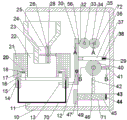
FIG. 1 is a schematic view of the whole apple packaging device of the present invention;
FIG. 2 is a front view of the rear side of the overall full section of FIG. 1;
FIG. 3 is a schematic view taken along the line A-A in FIG. 1;
fig. 4 is a schematic view of the direction B-B in fig. 1.
Detailed Description
The invention will now be described in detail with reference to fig. 1-4, wherein for ease of description the orientations described hereinafter are now defined as follows: the up, down, left, right, and front-back directions described below correspond to the up, down, left, right, and front-back directions in the projection relationship of fig. 1 itself.
The mechanical mechanism of the apple packaging device described with reference to fig. 1-4 comprises a sub-packaging block 10, a working cavity 11 with a leftward opening is arranged in the subpackaging block 10, a boxing mechanism 70 is arranged in the working cavity 11, the boxing mechanism 70 comprises a connecting block 21 fixed on the rear end wall of the working chamber 11, a through hole 22 which is communicated up and down is arranged in the connecting block 21, a storage frame 24 is fixedly arranged on the rear end wall of the through opening 22, a storage cavity 23 is arranged in the storage frame 24, a rotating cavity 25 is arranged on the left end wall and the right end wall of the storage cavity 23 in a penetrating way, a transmission shaft 28 is arranged on the rear end wall of the rotating cavity 25 in a rotating way, four rotating plates 26 are fixedly arranged on the transmission shaft 28, a first belt pulley 52 is fixedly arranged on the transmission shaft 28, the first belt wheel 52 is arranged at the rear side of the transmission shaft 28, the belt 48 is wound on the first belt wheel 52, and the rotation plate 26 rotates to enable the apples in the storage cavity 23 to move downwards;
the right side of the boxing mechanism 70 is provided with a moving mechanism 71, the moving mechanism 71 comprises a push rod 45, the rear end wall of the working chamber 11 is provided with a push-off groove 43, the push rod 45 is arranged in the push-off groove 43 and can move left and right, a push-off block 47 is fixedly arranged on the right end face of the push rod 45, a stressed rod 42 is fixedly arranged on the upper end face of the push rod 45, the rear end wall of the working chamber 11 is rotatably provided with a transverse shaft 46, a contact gear 64 and a disc 40 are fixedly arranged on the transverse shaft 46 from back to front in sequence, a driving rod 41 is fixedly arranged on the contact gear 64, and the driving rod 41 can drive the push-off block 47 to move left by rotating;
the mountain bike moving mechanism 71 is provided with a rotating mechanism 72, the rotating mechanism 72 comprises a carrying block 58, a sliding groove 55 is formed in the rear end wall of the working cavity 11, the carrying block 58 is arranged in the sliding groove 55 in a left-right moving mode, a fixing spring 57 is connected between the left end face of the carrying block 58 and the left end wall of the sliding groove 55, a thin wire 56 is fixedly arranged on the left end face of the carrying block 58, a motor 60 is fixedly arranged on the front end face of the carrying block 58, a motor shaft 33 is arranged on the front end face of the motor 60 in a circumferential rotating mode, and a motor gear 32 is fixedly arranged on the motor shaft 33.
Advantageously, the boxing mechanism 70 is described in detail, the boxing mechanism 70 further includes a sliding block 17, two sliding cavities 16 with downward openings are symmetrically arranged on the lower end surface of the connecting block 21 in a left-right manner, taking the sliding cavity 16 on the left side as an example, a clamping groove 18 is arranged on the rear end wall of the sliding cavity 16, the sliding block 17 is arranged in the clamping groove 18 in a left-right movable manner, a clamping spring 20 is arranged between the right end surface of the sliding block 17 and the right end wall of the clamping groove 18, a clamping plate 15 is fixedly arranged on the front end surface of the sliding block 17, two fixing plates 14 are fixedly arranged on the lower end surface of the connecting block 21 in a left-right symmetrical manner, and a cross bar 13 is fixedly.
Advantageously, the moving mechanism 71 is described in detail, the moving mechanism 71 further includes two transmission blocks 61 fixed on the transverse shaft 46, two transmission grooves 62 are provided in the contact gear 64, for example, the transmission groove 62 on the left side is taken as an example, a contact block 63 is provided in the transmission groove 62 to be movable left and right, a contact spring 65 is connected between the left end surface of the contact block 63 and the left end wall of the transmission groove 62, a moving groove 37 is provided on the rear end wall of the working chamber 11, a transverse rack 36 is provided in the moving groove 37 to be movable left and right, an extension spring 38 is connected between the right end surface of the transverse rack 36 and the right end wall of the moving groove 37, a string 29 is connected to the right end surface of the transverse rack 36, the transverse rack 36 is engaged with the contact gear 64, and the transverse rack 36 can only drive the contact gear 64 to rotate clockwise.
Beneficially, the rotating mechanism 72 is described in detail, the rotating mechanism 72 further includes a driven shaft 35, a transmission cavity 50 is arranged in the rear end wall of the working cavity 11, the driven shaft 35 is arranged in the rotation of the rear end wall of the transmission cavity 50, a second belt pulley 54 and a driven gear 34 are sequentially and fixedly arranged on the driven shaft 35 from back to front, the belt 48 is wound on the second belt pulley 54, a pin 12 is fixedly arranged on the rear end wall of the sub-packaging block 10, a vertical rod 30 is arranged on the pin 12 in a rotating manner, a torsion spring 49 is arranged between the vertical rod 30 and the pin 12, the thin wire 56 is connected to the right end face of the vertical rod 30, and the thin rope 29 is connected to the right end face of the vertical rod.
Advantageously, the clamping spring 20 is in a compressed state, the extension spring 38, the return spring 44, the torsion spring 49, the contact spring 65 are in a normal state, and the clamping spring 20 is more elastic than the torsion spring 49.
Sequence of mechanical actions of the whole device:
(1) the apples to be packaged are placed in the storage cavity 23, a box for packaging the apples is clamped by the fixing plate 14 and the clamping plate 15, the motor 60 is started, the motor shaft 33 rotates along with the motor 60, and the motor shaft 33 drives the motor gear 32 to rotate. The motor gear 32 is meshed with the driven gear 34 to drive the driven gear 34 to rotate, the driven gear 34 drives the second belt wheel 54 to rotate through the driven shaft 35, the second belt wheel 54 drives the first belt wheel 52 to rotate through the belt 48 in a friction mode, the first belt wheel 52 drives the rotating plate 26 to rotate through the transmission shaft 28, and the rotating plate 26 rotates to enable apples in the storage cavity 23 to fall downwards into the apple box.
(2) When the apple in the apple box reaches a certain weight, the friction force provided by the fixing plate 14 and the clamping plate 15 is not enough to support the gravity of the apple box, the apple box falls downwards, the clamping spring 20 on the right side pushes the sliding block 17 to move rightwards, the clamping spring 20 drives the clamping plate 15 to move rightwards, and the cross rod 13 moves rightwards along with the clamping plate 15.
(3) The cross rod 13 pushes the vertical rod 30 to rotate, the vertical rod 30 rotates anticlockwise around the pin 12, the vertical rod 30 pulls the thin wire 56 to move leftwards, the thin wire 56 pulls the object carrying block 58 to move leftwards, the object carrying block 58 drives the motor 60 to move leftwards, the motor 60 drives the motor gear 32 to move leftwards through the motor shaft 33, the motor gear 32 moves leftwards and is disengaged from the driven gear 34, the driven gear 34 does not rotate any more, the transmission shaft 28 also can not rotate any more, and the apples in the storage cavity 23 can not drop downwards any more.
(4) The vertical rod 30 rotates, the transverse rack 36 is pulled by the string 29 to move rightwards, the transverse rack 36 moves rightwards to drive the contact gear 64 to rotate clockwise, the transverse rack 36 can drive the contact gear 64 to rotate just one circle, the contact gear 64 drives the transverse shaft 46 to rotate through the contact block 63 and the transmission block 61, the transverse shaft 46 drives the disc 40 to rotate clockwise, the disc 40 drives the driving rod 41 to rotate, the driving rod 41 pushes the stress rod 42 to move leftwards, the stress rod 42 drives the pushing rod 45 to move leftwards, the pushing block 47 moves leftwards along with the pushing block 47, and the pushing block 47 pushes the apple box filled with apples out of the working cavity 11.
(5) When the apple box is reloaded, the rack 36 moves to the right but does not rotate the contact gear 64, and the carrier block 58 moves to the right, so that the motor gear 32 is meshed with the driven gear 34.
The above embodiments are merely illustrative of the technical ideas and features of the present invention, and the purpose thereof is to enable those skilled in the art to understand the contents of the present invention and implement the present invention, and not to limit the protection scope of the present invention. All equivalent changes and modifications made according to the spirit of the present invention should be covered within the protection scope of the present invention.
Claims (5)
1. The utility model provides an apple equipment for packing, includes partial shipment piece, its characterized in that:
a working cavity with a leftward opening is formed in the subpackaging block, a boxing mechanism is arranged in the working cavity and comprises a connecting block fixed on the rear end wall of the working cavity, a through hole which is communicated up and down is formed in the connecting block, a storage frame is fixedly arranged on the rear end wall of the through hole, a storage cavity is formed in the storage frame, a rotating cavity is formed in the left end wall and right end wall of the storage cavity in a communicating mode, a transmission shaft is rotatably arranged on the rear end wall of the rotating cavity, four rotating plates are fixedly arranged on the transmission shaft, a first belt wheel is fixedly arranged on the transmission shaft and arranged on the rear side of the transmission shaft, a belt is wound on the first belt wheel, and the rotating plates rotate to enable apples in the storage cavity to move downwards;
the right side of the boxing mechanism is provided with a moving mechanism, the moving mechanism comprises a push rod, the rear end wall of the working cavity is provided with a push-off groove, the push rod is arranged in the push-off groove in a left-right moving mode, a push-off block is fixedly arranged on the right end face of the push rod, a stress rod is fixedly arranged on the upper end face of the push rod, the rear end wall of the working cavity is rotatably provided with a cross shaft, a contact gear and a disc are fixedly arranged on the cross shaft from back to front in sequence, a driving rod is fixedly arranged on the contact gear, and the driving rod can drive the push-off block to move leftwards through rotation;
the mountain bike with the moving mechanism is provided with a rotating mechanism, the rotating mechanism comprises a carrying block, a sliding groove is formed in the rear end wall of the working cavity, the carrying block can move left and right in the sliding groove, a fixing spring is connected between the left end face of the carrying block and the left end wall of the sliding groove, a fine wire is fixedly arranged on the left end face of the carrying block, a motor is fixedly arranged on the front end face of the carrying block, a motor shaft is arranged on the front end face of the motor in a rotating mode, and a motor gear is fixedly arranged on the motor shaft.
2. The apple packaging apparatus of claim 1, wherein: the boxing mechanism further comprises a sliding block, the end face bilateral symmetry is provided with two sliding cavities with downward openings under the connecting block, the left side is taken as an example of the sliding cavities, the rear end wall of each sliding cavity is provided with a clamping groove, the sliding block can move left and right in the clamping groove, the right end face of the sliding block is provided with a clamping spring between the right end walls of the clamping grooves, the front end face of the sliding block is fixedly provided with a clamping plate, the end face bilateral symmetry is fixedly provided with two fixing plates and the right side under the connecting block, and the rear end face of the clamping plate is fixedly provided with a transverse rod.
3. The apple packaging apparatus of claim 1, wherein: the moving mechanism is characterized by further comprising two transmission blocks fixed on the cross shaft, two transmission grooves are formed in the contact gear, the left side is used as an example of the transmission grooves, contact blocks are arranged in the transmission grooves in a left-and-right moving mode, contact springs are connected between the left end face of each contact block and the left end wall of each transmission groove, a moving groove is formed in the rear end wall of the working cavity, a cross rack is arranged in the moving groove in a left-and-right moving mode, a telescopic spring is connected between the right end face of the cross rack and the right end wall of each moving groove, a string is connected to the right end face of the cross rack, the cross rack is meshed with the contact gear, and the cross rack can only drive.
4. The apple packaging apparatus of claim 3, wherein: slewing mechanism still includes the driven shaft, be equipped with the transmission chamber in the working chamber rear end wall, transmission chamber rear end wall rotates and is equipped with the driven shaft, from fixed second band pulley and the driven gear of being equipped with forward in proper order backward on the driven shaft, around having on the second band pulley the belt, the fixed pin that is equipped with of partial shipment piece rear end wall, it is equipped with the montant to rotate on the pin, the montant with be equipped with the torsional spring between the pin, the montant right-hand member face is connected with the fine rule, the montant right-hand member face is connected with the string.
5. The apple packaging apparatus of claim 4, wherein: the clamping spring is in a compression state, the extension spring, the reset spring, the torsion spring and the contact spring are in a normal state, and the elasticity of the clamping spring is larger than that of the torsion spring.
Priority Applications (1)
| Application Number | Priority Date | Filing Date | Title |
|---|---|---|---|
| CN201911044193.XA CN110683082A (en) | 2019-10-30 | 2019-10-30 | Apple equipment for packing |
Applications Claiming Priority (1)
| Application Number | Priority Date | Filing Date | Title |
|---|---|---|---|
| CN201911044193.XA CN110683082A (en) | 2019-10-30 | 2019-10-30 | Apple equipment for packing |
Publications (1)
| Publication Number | Publication Date |
|---|---|
| CN110683082A true CN110683082A (en) | 2020-01-14 |
Family
ID=69114803
Family Applications (1)
| Application Number | Title | Priority Date | Filing Date |
|---|---|---|---|
| CN201911044193.XA Withdrawn CN110683082A (en) | 2019-10-30 | 2019-10-30 | Apple equipment for packing |
Country Status (1)
| Country | Link |
|---|---|
| CN (1) | CN110683082A (en) |
Cited By (2)
| Publication number | Priority date | Publication date | Assignee | Title |
|---|---|---|---|---|
| CN112758366A (en) * | 2020-12-15 | 2021-05-07 | 清远市大园围农业有限公司 | Continuous bean sprout production system |
| CN118928900A (en) * | 2024-09-29 | 2024-11-12 | 佛山市盛世达塑料有限公司 | A material receiving mechanism for PVC sheet calendering equipment |
Citations (8)
| Publication number | Priority date | Publication date | Assignee | Title |
|---|---|---|---|---|
| JP2000255502A (en) * | 1999-03-08 | 2000-09-19 | Nippon Steel Corp | Automatic sphere filling device |
| CN2701754Y (en) * | 2004-04-16 | 2005-05-25 | 武汉人天包装技术有限公司 | Automatic container loader |
| CN204802127U (en) * | 2015-06-04 | 2015-11-25 | 西安理工大学 | Automatic fruit packagine machine |
| CN105599931A (en) * | 2016-03-04 | 2016-05-25 | 无锡中阳包装技术有限公司 | Dye packing machine |
| CN107458641A (en) * | 2017-09-27 | 2017-12-12 | 佛山市深研信息技术有限公司 | A kind of environment-friendly type building stones automated packaging equipment |
| CN207072446U (en) * | 2017-07-10 | 2018-03-06 | 河南水利与环境职业学院 | A kind of particle boxing apparatus |
| CN208036770U (en) * | 2018-03-19 | 2018-11-02 | 柏乡县华兴纸业包装有限公司 | A kind of fixing device of Packaging Box |
| CN208278462U (en) * | 2018-06-07 | 2018-12-25 | 奉节县茗啟生态农业有限公司 | Quantitative racking machine is used in a kind of plantation of navel orange |
-
2019
- 2019-10-30 CN CN201911044193.XA patent/CN110683082A/en not_active Withdrawn
Patent Citations (8)
| Publication number | Priority date | Publication date | Assignee | Title |
|---|---|---|---|---|
| JP2000255502A (en) * | 1999-03-08 | 2000-09-19 | Nippon Steel Corp | Automatic sphere filling device |
| CN2701754Y (en) * | 2004-04-16 | 2005-05-25 | 武汉人天包装技术有限公司 | Automatic container loader |
| CN204802127U (en) * | 2015-06-04 | 2015-11-25 | 西安理工大学 | Automatic fruit packagine machine |
| CN105599931A (en) * | 2016-03-04 | 2016-05-25 | 无锡中阳包装技术有限公司 | Dye packing machine |
| CN207072446U (en) * | 2017-07-10 | 2018-03-06 | 河南水利与环境职业学院 | A kind of particle boxing apparatus |
| CN107458641A (en) * | 2017-09-27 | 2017-12-12 | 佛山市深研信息技术有限公司 | A kind of environment-friendly type building stones automated packaging equipment |
| CN208036770U (en) * | 2018-03-19 | 2018-11-02 | 柏乡县华兴纸业包装有限公司 | A kind of fixing device of Packaging Box |
| CN208278462U (en) * | 2018-06-07 | 2018-12-25 | 奉节县茗啟生态农业有限公司 | Quantitative racking machine is used in a kind of plantation of navel orange |
Cited By (3)
| Publication number | Priority date | Publication date | Assignee | Title |
|---|---|---|---|---|
| CN112758366A (en) * | 2020-12-15 | 2021-05-07 | 清远市大园围农业有限公司 | Continuous bean sprout production system |
| CN112758366B (en) * | 2020-12-15 | 2022-04-12 | 清远市大园围农业有限公司 | Continuous bean sprout production system |
| CN118928900A (en) * | 2024-09-29 | 2024-11-12 | 佛山市盛世达塑料有限公司 | A material receiving mechanism for PVC sheet calendering equipment |
Similar Documents
| Publication | Publication Date | Title |
|---|---|---|
| CN203937868U (en) | A kind of black tea wrapping machine | |
| CN110683082A (en) | Apple equipment for packing | |
| CN110979845B (en) | A sticky tape coiler for packing express delivery case | |
| CN104477433B (en) | A kind of double knotted candy package machine | |
| CN109807069B (en) | Intelligent visual identification logistics package screening equipment | |
| CN110116838A (en) | A kind of rich potassium type organic fertilizer packaging equipment of half wet condition | |
| CN111453086B (en) | Automatic feeding and cap screwing packaging machine | |
| CN205396679U (en) | Zongzi material cup clamp holds positioning mechanism | |
| CN112498762A (en) | Fruit selling equipment with automatic weighing and packing functions | |
| CN112407403A (en) | Quick wrapping device and wrapping method for packaging rice dumplings | |
| CN111572864A (en) | E-sheet automatic grabbing and boxing device | |
| CN209643386U (en) | A kind of bale packing transfer device of baling press | |
| CN113443221B (en) | Packaging box packaging equipment | |
| CN112623355B (en) | Be used for small-size fruit automatic counting baling press in supermarket | |
| CN216140465U (en) | Automatic change general material frame | |
| CN206068247U (en) | A kind of vacuum packing machine | |
| CN214524858U (en) | Positioning mechanism for packaging equipment | |
| CN112193454A (en) | Automatic weighing and packing device after tea leaves are picked | |
| CN214824469U (en) | A packaging machine for finished products | |
| CN111999242A (en) | Conveyer belt surface friction check out test set | |
| CN221395223U (en) | Large-sized product axial locking mechanism for packaging box | |
| CN207123546U (en) | A kind of semiconductor power test fixture | |
| CN218288260U (en) | High-precision anti-channeling device for roller frame | |
| CN109699311A (en) | A kind of bale packing transfer device of baling press | |
| CN222247938U (en) | Packaging equipment for quick-frozen food production |
Legal Events
| Date | Code | Title | Description |
|---|---|---|---|
| PB01 | Publication | ||
| PB01 | Publication | ||
| SE01 | Entry into force of request for substantive examination | ||
| SE01 | Entry into force of request for substantive examination | ||
| WW01 | Invention patent application withdrawn after publication | ||
| WW01 | Invention patent application withdrawn after publication |
Application publication date: 20200114 |