CN110732425A - kinds of foaming gun - Google Patents
kinds of foaming gun Download PDFInfo
- Publication number
- CN110732425A CN110732425A CN201911247331.4A CN201911247331A CN110732425A CN 110732425 A CN110732425 A CN 110732425A CN 201911247331 A CN201911247331 A CN 201911247331A CN 110732425 A CN110732425 A CN 110732425A
- Authority
- CN
- China
- Prior art keywords
- gun
- foaming
- joint
- claw
- barrel
- Prior art date
- Legal status (The legal status is an assumption and is not a legal conclusion. Google has not performed a legal analysis and makes no representation as to the accuracy of the status listed.)
- Pending
Links
Images



Classifications
-
- B—PERFORMING OPERATIONS; TRANSPORTING
- B65—CONVEYING; PACKING; STORING; HANDLING THIN OR FILAMENTARY MATERIAL
- B65D—CONTAINERS FOR STORAGE OR TRANSPORT OF ARTICLES OR MATERIALS, e.g. BAGS, BARRELS, BOTTLES, BOXES, CANS, CARTONS, CRATES, DRUMS, JARS, TANKS, HOPPERS, FORWARDING CONTAINERS; ACCESSORIES, CLOSURES, OR FITTINGS THEREFOR; PACKAGING ELEMENTS; PACKAGES
- B65D83/00—Containers or packages with special means for dispensing contents
- B65D83/14—Containers for dispensing liquid or semi-liquid contents by internal gaseous pressure, i.e. aerosol containers comprising propellant
- B65D83/16—Actuating means
- B65D83/164—Actuators comprising a manually operated valve and being attachable to the aerosol container, e.g. downstream a valve fitted to the container; Actuators associated to container valves with valve seats located outside the aerosol container
-
- B—PERFORMING OPERATIONS; TRANSPORTING
- B05—SPRAYING OR ATOMISING IN GENERAL; APPLYING FLUENT MATERIALS TO SURFACES, IN GENERAL
- B05B—SPRAYING APPARATUS; ATOMISING APPARATUS; NOZZLES
- B05B11/00—Single-unit hand-held apparatus in which flow of contents is produced by the muscular force of the operator at the moment of use
- B05B11/0005—Components or details
- B05B11/0008—Sealing or attachment arrangements between sprayer and container
-
- B—PERFORMING OPERATIONS; TRANSPORTING
- B05—SPRAYING OR ATOMISING IN GENERAL; APPLYING FLUENT MATERIALS TO SURFACES, IN GENERAL
- B05B—SPRAYING APPARATUS; ATOMISING APPARATUS; NOZZLES
- B05B1/00—Nozzles, spray heads or other outlets, with or without auxiliary devices such as valves, heating means
- B05B1/02—Nozzles, spray heads or other outlets, with or without auxiliary devices such as valves, heating means designed to produce a jet, spray, or other discharge of particular shape or nature, e.g. in single drops, or having an outlet of particular shape
- B05B1/04—Nozzles, spray heads or other outlets, with or without auxiliary devices such as valves, heating means designed to produce a jet, spray, or other discharge of particular shape or nature, e.g. in single drops, or having an outlet of particular shape in flat form, e.g. fan-like, sheet-like
- B05B1/044—Slits, e.g. narrow openings defined by two straight and parallel lips; Elongated outlets for producing very wide discharges, e.g. fluid curtains
-
- B—PERFORMING OPERATIONS; TRANSPORTING
- B05—SPRAYING OR ATOMISING IN GENERAL; APPLYING FLUENT MATERIALS TO SURFACES, IN GENERAL
- B05B—SPRAYING APPARATUS; ATOMISING APPARATUS; NOZZLES
- B05B11/00—Single-unit hand-held apparatus in which flow of contents is produced by the muscular force of the operator at the moment of use
- B05B11/0005—Components or details
-
- B—PERFORMING OPERATIONS; TRANSPORTING
- B05—SPRAYING OR ATOMISING IN GENERAL; APPLYING FLUENT MATERIALS TO SURFACES, IN GENERAL
- B05B—SPRAYING APPARATUS; ATOMISING APPARATUS; NOZZLES
- B05B11/00—Single-unit hand-held apparatus in which flow of contents is produced by the muscular force of the operator at the moment of use
- B05B11/0005—Components or details
- B05B11/0089—Dispensing tubes
-
- B—PERFORMING OPERATIONS; TRANSPORTING
- B05—SPRAYING OR ATOMISING IN GENERAL; APPLYING FLUENT MATERIALS TO SURFACES, IN GENERAL
- B05B—SPRAYING APPARATUS; ATOMISING APPARATUS; NOZZLES
- B05B13/00—Machines or plants for applying liquids or other fluent materials to surfaces of objects or other work by spraying, not covered by groups B05B1/00 - B05B11/00
- B05B13/02—Means for supporting work; Arrangement or mounting of spray heads; Adaptation or arrangement of means for feeding work
- B05B13/0278—Arrangement or mounting of spray heads
-
- B—PERFORMING OPERATIONS; TRANSPORTING
- B05—SPRAYING OR ATOMISING IN GENERAL; APPLYING FLUENT MATERIALS TO SURFACES, IN GENERAL
- B05B—SPRAYING APPARATUS; ATOMISING APPARATUS; NOZZLES
- B05B15/00—Details of spraying plant or spraying apparatus not otherwise provided for; Accessories
- B05B15/50—Arrangements for cleaning; Arrangements for preventing deposits, drying-out or blockage; Arrangements for detecting improper discharge caused by the presence of foreign matter
-
- B—PERFORMING OPERATIONS; TRANSPORTING
- B65—CONVEYING; PACKING; STORING; HANDLING THIN OR FILAMENTARY MATERIAL
- B65D—CONTAINERS FOR STORAGE OR TRANSPORT OF ARTICLES OR MATERIALS, e.g. BAGS, BARRELS, BOTTLES, BOXES, CANS, CARTONS, CRATES, DRUMS, JARS, TANKS, HOPPERS, FORWARDING CONTAINERS; ACCESSORIES, CLOSURES, OR FITTINGS THEREFOR; PACKAGING ELEMENTS; PACKAGES
- B65D83/00—Containers or packages with special means for dispensing contents
- B65D83/14—Containers for dispensing liquid or semi-liquid contents by internal gaseous pressure, i.e. aerosol containers comprising propellant
- B65D83/75—Aerosol containers not provided for in groups B65D83/16 - B65D83/74
- B65D83/756—Aerosol containers not provided for in groups B65D83/16 - B65D83/74 comprising connectors, e.g. for tyre valves, or actuators connected to the aerosol container by a flexible tube
-
- B—PERFORMING OPERATIONS; TRANSPORTING
- B65—CONVEYING; PACKING; STORING; HANDLING THIN OR FILAMENTARY MATERIAL
- B65D—CONTAINERS FOR STORAGE OR TRANSPORT OF ARTICLES OR MATERIALS, e.g. BAGS, BARRELS, BOTTLES, BOXES, CANS, CARTONS, CRATES, DRUMS, JARS, TANKS, HOPPERS, FORWARDING CONTAINERS; ACCESSORIES, CLOSURES, OR FITTINGS THEREFOR; PACKAGING ELEMENTS; PACKAGES
- B65D83/00—Containers or packages with special means for dispensing contents
- B65D83/14—Containers for dispensing liquid or semi-liquid contents by internal gaseous pressure, i.e. aerosol containers comprising propellant
- B65D83/68—Dispensing two or more contents
Landscapes
- Chemical & Material Sciences (AREA)
- Dispersion Chemistry (AREA)
- Engineering & Computer Science (AREA)
- Mechanical Engineering (AREA)
- Nozzles (AREA)
Abstract
一种发泡枪,包括枪体、设于枪体前端的枪管以及设于枪体尾端下方的枪柄,枪体上设有与枪柄相匹配的扳机,枪管前端设有枪嘴,枪管内设有与枪嘴相匹配的顶杆,枪体上方设有连接头,连接头连接有发泡罐,所述连接头连接有若干爪接头;所述爪接头下表面中心设有一与连接头相匹配的螺纹部;所述爪接头上表面中部设有一凹槽,凹槽槽底设有一与螺纹部相贯通的适配管。本发明的发泡枪能够实现自身与发泡罐连接时的快速连接,即使同时连接至少两个以上的发泡罐,同样能够保证连接效率,且无需对发泡枪进行完全拆卸,便能够对枪体残留的固化发泡料进行快速清理,并可以实现发泡枪的大范围喷涂。
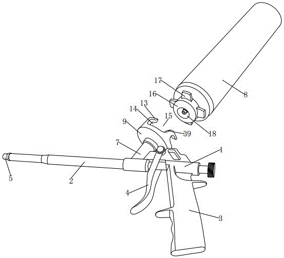
A foaming gun comprises a gun body, a gun barrel arranged at the front end of the gun body, and a gun handle arranged below the rear end of the gun body, the gun body is provided with a trigger matching the gun handle, and the front end of the gun barrel is provided with a gun nozzle , the gun barrel is provided with an ejector rod that matches the gun mouth, a connecting head is arranged above the gun body, the connecting head is connected with a foaming tank, and the connecting head is connected with a number of claw joints; the center of the lower surface of the claw joint is provided with a The threaded portion of the connecting head is matched; a groove is arranged in the middle part of the upper surface of the claw joint, and an adapter tube which is communicated with the threaded portion is arranged at the bottom of the groove. The foaming gun of the present invention can realize the quick connection when it is connected with the foaming tank, even if at least two foaming tanks are connected at the same time, the connection efficiency can also be guaranteed, and the foaming gun can be completely disassembled. The solidified foaming material remaining in the gun body can be quickly cleaned, and the large-scale spraying of the foaming gun can be realized.
Description
技术领域technical field
本发明涉及一种发泡枪。The present invention relates to a foaming gun.
背景技术Background technique
发泡枪通过喷涂发泡料以实现安装、填缝、补漏和粘接等功能,因此被广泛应用于装潢业。而发泡料都是填充在发泡料罐中,当发泡料罐安装在发泡枪身上时,发泡枪便可通过枪体上的扳机将发泡料喷涂出去。Foaming guns are widely used in the decoration industry by spraying foaming materials to achieve the functions of installation, caulking, leak repair and bonding. The foaming material is filled in the foaming material tank. When the foaming material tank is installed on the foaming gun, the foaming gun can spray the foaming material through the trigger on the gun body.
传统的发泡枪与发泡罐之间通过螺纹连接的方式实现固定,这种固定方式为了保证稳固性,则需要发泡罐在与发泡枪的连接头进行螺纹连接时旋转很多圈,显得极为麻烦,严重影响发泡罐的拆装效率,不利于发泡罐的更换,且发泡枪有时候并非单单连接一个发泡罐,当发泡枪需要连接两个或两个以上的发泡罐时,发泡枪上则会通过多头软管连接至少两个以上的发泡罐,此时若依旧采用螺纹连接的方式,多头软管进行螺接的软管头则会受到彼此的限制,出现扭曲变形的情况,易导致软管内部管道受阻,发泡罐内的发泡料无法顺利通过多头软管进入至发泡枪内,影响发泡枪的正常使用。The traditional foaming gun and the foaming tank are fixed by threaded connection. In order to ensure the stability, the foaming tank needs to be rotated many times when the connection head of the foaming gun is threadedly connected. It is extremely troublesome, seriously affects the disassembly and assembly efficiency of the foaming tank, and is not conducive to the replacement of the foaming tank. Sometimes the foaming gun is not connected to only one foaming tank. When the foaming gun needs to connect two or more foaming tanks When the tank is used, the foaming gun will connect at least two or more foaming tanks through a multi-head hose. At this time, if the threaded connection is still used, the hose heads that are screwed by the multi-head hose will be restricted by each other. In the case of twisting and deformation, it is easy to cause the internal pipeline of the hose to be blocked, and the foaming material in the foaming tank cannot smoothly enter the foaming gun through the multi-headed hose, which affects the normal use of the foaming gun.
当发泡枪进行使用时,发泡料必然会经过枪体安装有气阀的进料腔以及枪管,而发泡料每一次被喷涂出,不可避免的会有部分残留在进料腔与枪管内,长此以往,易出现残留下来的发泡料固化导致喷涂通道受阻的情况,遇到这种情况,由于枪体为封闭结构,因此只能将发泡枪完全拆除,才能对进料腔以及枪管内的发泡料进行清理,这种清理方式极为麻烦,清理效率极低。When the foaming gun is used, the foaming material will inevitably pass through the feed cavity and the barrel of the gun body with the air valve installed, and every time the foaming material is sprayed out, it is inevitable that some of the foaming material will remain in the feeding cavity and the barrel. In the gun barrel, in the long run, it is easy to cause the residual foaming material to solidify and cause the spraying channel to be blocked. In this case, because the gun body is a closed structure, the foaming gun can only be completely removed to prevent the feeding cavity and The foaming material in the barrel is cleaned, this cleaning method is extremely troublesome and the cleaning efficiency is extremely low.
传统的发泡枪的枪嘴为圆条状喷涂孔,这种枪嘴喷涂出来的发泡料的形状同样为条状,而条状发泡料能够形成的覆盖面积极为有限,若是要进行大面积的喷涂工作,采用这种枪嘴,则需要消耗大量的时间,喷涂效率极为低下。The nozzle of the traditional foaming gun is a round strip-shaped spray hole. The shape of the foaming material sprayed by this nozzle is also strip-shaped, and the coverage area that the strip-shaped foaming material can form is extremely limited. For the spraying work of the area, using this nozzle will consume a lot of time, and the spraying efficiency is extremely low.
发明内容SUMMARY OF THE INVENTION
本发明要解决的技术问题是提供一种发泡枪,它能够实现自身与发泡罐连接时的快速连接,即使同时连接至少两个以上的发泡罐,同样能够保证连接效率,且无需对发泡枪进行完全拆卸,便能够对枪体残留的固化发泡料进行快速清理,并可以实现发泡枪的大范围喷涂。The technical problem to be solved by the present invention is to provide a foaming gun, which can realize the quick connection when connecting itself with the foaming tank. Even if at least two foaming tanks are connected at the same time, the connection efficiency can also be ensured, and no When the foaming gun is completely disassembled, the solidified foaming material remaining in the gun body can be quickly cleaned, and the large-scale spraying of the foaming gun can be realized.
本发明解决上述技术问题采用的技术方案为:The technical scheme adopted by the present invention to solve the above-mentioned technical problems is:
本发明公开一种发泡枪,包括枪体、设于枪体前端的枪管以及设于枪体尾端下方的枪柄,枪体上设有与枪柄相匹配的扳机,枪管前端设有枪嘴,枪管内设有与枪嘴相匹配的顶杆,枪体上方设有连接头,连接头连接有发泡罐,其特征在于:所述连接头连接有若干爪接头;所述爪接头下表面中心设有一与连接头相匹配的螺纹部;所述爪接头上表面中部设有一凹槽,凹槽槽底设有一与螺纹部相贯通的适配管;所述爪接头上表面边沿设有若干呈圆周均匀分布的卡爪;所述卡爪与爪接头上表面之间形成一卡槽,相邻的卡爪之间具有与卡槽相贯通的卡入间隙;所述发泡罐下端设有一与凹槽相匹配的安装头;所述安装头外周面设有若干与卡爪个数相对应的旋转卡板,旋转卡板的宽度小于卡入间隙的宽度,旋转卡板的厚度小于卡槽的槽高;所述安装头下表面中心设有与适配管相匹配的对接孔。The invention discloses a foaming gun, comprising a gun body, a gun barrel arranged at the front end of the gun body, and a gun handle arranged below the rear end of the gun body. There is a gun mouth, the barrel is provided with an ejector rod that matches the gun mouth, a connecting head is arranged above the gun body, and the connecting head is connected with a foaming tank, which is characterized in that: the connecting head is connected with a number of claw joints; The center of the lower surface of the joint is provided with a threaded portion that matches the connecting head; the middle of the upper surface of the claw joint is provided with a groove, and the bottom of the groove is provided with an adapter tube that communicates with the threaded portion; the edge of the upper surface of the claw joint There are several clamping claws evenly distributed around the circumference; a clamping groove is formed between the clamping claws and the upper surface of the claw joint, and there is a clamping gap connected with the clamping groove between the adjacent clamping claws; the foaming tank The lower end is provided with a mounting head that matches the groove; the outer peripheral surface of the mounting head is provided with a number of rotating card plates corresponding to the number of claws, the width of the rotating card plate is smaller than the width of the clamping gap, and the thickness of the rotating card plate The height of the slot is smaller than the slot height of the card slot; the center of the lower surface of the mounting head is provided with a butt hole matching with the adapter tube.
所述枪管一侧外壁上设有若干均匀分布的清理窗;所述清理窗上盖合有与其相匹配的窗盖,窗盖通过紧固螺丝固定于枪管上;所述枪体内设有与连接头相贯通的进料腔,枪体一侧外壁设有与进料腔相贯通的清理孔;所述清理孔螺接有密封螺丝。A number of evenly distributed cleaning windows are arranged on the outer wall of one side of the barrel; the cleaning window is covered with a matching window cover, and the window cover is fixed on the barrel by tightening screws; the gun body is provided with The feeding cavity communicated with the connecting head, and the outer wall of one side of the gun body is provided with a cleaning hole communicated with the feeding cavity; the cleaning hole is screwed with a sealing screw.
所述窗盖与清理窗相对的一侧侧壁设有一密封槽;所述密封槽内设有与其相匹配的密封圈。The side wall of the window cover opposite to the cleaning window is provided with a sealing groove; the sealing groove is provided with a matching sealing ring.
所述清理孔下端孔口设有一卡位台阶,密封螺丝的头部卡于卡位台阶上;所述密封螺丝的头部与卡位台阶之间设有一密封垫片。The opening of the lower end of the cleaning hole is provided with a clamping step, and the head of the sealing screw is clamped on the clamping step; a sealing gasket is arranged between the head of the sealing screw and the clamping step.
所述枪嘴前端设有喷洒头;所述喷洒头前端端面设有一扁平开口或扁平扩增口,扁平扩增口横截面呈前宽后窄的三角状。The front end of the gun nozzle is provided with a spray head; the front end face of the spray head is provided with a flat opening or a flat expansion port, and the cross section of the flat expansion port is in the shape of a triangle with a wide front and a narrow back.
所述连接头螺接有第一螺接头,第一螺接头连接有第一软管;所述第一软管端部连接有一快速接头;所述快速接头上设有一主接口以及至少两个以上的分接口,主接口与第一软管相连接,分接口连接有第二软管;所述第二软管端部连接有第二螺接头,爪接头通过螺纹部与第二螺接头相螺接。The connecting head is screwed with a first screw joint, and the first screw joint is connected with a first hose; the end of the first hose is connected with a quick joint; the quick joint is provided with a main interface and at least two or more The main interface is connected with the first hose, and the sub-port is connected with a second hose; the end of the second hose is connected with a second screw joint, and the claw joint is screwed with the second screw joint through the threaded part catch.
所述爪接头上表面与卡爪外壁之间通过一呈弧状的导向面过渡连接。The upper surface of the claw joint and the outer wall of the clamping claw are transitionally connected through an arc-shaped guide surface.
本发明的有益效果是:The beneficial effects of the present invention are:
与现有技术相比,采用本发明结构的发泡枪只需将旋转卡板通过卡入间隙下移至与卡槽槽口齐平的位置,再将旋转卡板旋转至与卡入间隙相贯通的卡槽内,便能够实现发泡枪与发泡罐之间的固定,这种旋转动作极小,只需一下便能够快速完成,连接效率远超螺纹连接需要旋转许多圈才能完成紧固的情况,从而实现发泡枪与发泡罐之间的快速连接,由于爪接头与旋转卡板之间的连接只需旋转较小的角度便能完成,因此发泡腔与多个发泡罐进行连接时,软管扭曲变形的角度有限,不会影响软管对发泡料的输送,有效避免由于软管扭曲变形过度导致内部堵塞无法流通的情况。Compared with the prior art, the foaming gun using the structure of the present invention only needs to move the rotating card plate down to the position flush with the slot of the card slot through the card-in gap, and then rotate the rotating card plate to a position in line with the card-in gap. In the through slot, the fixing between the foaming gun and the foaming tank can be realized. This kind of rotation action is very small and can be completed quickly with just one click. The connection efficiency is much higher than that of the threaded connection, which requires many rotations to complete the fastening. Therefore, the quick connection between the foaming gun and the foaming tank can be realized. Since the connection between the claw joint and the rotating card plate can be completed only by rotating a small angle, the foaming cavity is connected to multiple foaming tanks. When connecting, the twisting and deformation angle of the hose is limited, which will not affect the conveying of the foam material by the hose, and effectively avoid the situation that the internal blockage cannot flow due to excessive twisting and deformation of the hose.
与现有技术相比,采用本发明结构的发泡枪能够通过清理窗直接对残留在枪管内的固化发泡料进行清理,也可通过清理孔直接对残留在进料腔内的固化发泡料进行清理,有效避免需要将发泡枪完全拆卸才能对枪管内部以及进料腔进行清理的情况,当残留的固化发泡料清理完成后,再将窗盖盖合于清理窗上便可再次将枪管内部空间重新变成密闭空间,再将密封螺丝紧固在清理孔内便可再次将进料腔变成密闭空间,而密封圈与密封垫片的存在能够分别保证枪管与进料腔的密封性,避免出现喷涂时发泡料泄漏的情况。Compared with the prior art, the foaming gun using the structure of the present invention can directly clean the solidified foaming material remaining in the gun barrel through the cleaning window, and can also directly clean the solidified foaming material remaining in the feeding cavity through the cleaning hole. It can effectively avoid the need to completely disassemble the foaming gun to clean the inside of the barrel and the feeding cavity. When the residual solidified foaming material is cleaned, the window cover can be closed on the cleaning window The inner space of the barrel is turned into a closed space again, and then the sealing screw is fastened in the cleaning hole to turn the feeding cavity into a closed space again, and the existence of the sealing ring and the sealing gasket can ensure the barrel and the feeding cavity respectively. The tightness of the material cavity can avoid the leakage of foaming material during spraying.
与现有技术相比,采用本发明结构的发泡枪能够通过扁平开口与扁平扩增口对喷出的发泡料进行整形发散,使其喷涂形状从条状转变成前宽后窄的扇形扁平状,从而起到增大喷涂范围的效果,有效提高喷涂效率。Compared with the prior art, the foaming gun adopting the structure of the present invention can shape and disperse the sprayed foaming material through the flat opening and the flat expansion port, so that the spraying shape changes from a strip shape to a fan shape with a wide front and a narrow back. Flat shape, so as to increase the spraying range and effectively improve the spraying efficiency.
附图说明Description of drawings
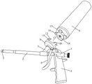
图1是本发明发泡枪的结构示意图;Fig. 1 is the structural representation of foaming gun of the present invention;
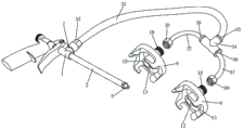
图2是发泡枪连接有两个爪接头时的结构示意图;Fig. 2 is the structural representation when the foaming gun is connected with two claw joints;
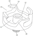
图3是爪接头的一个角度的结构示意图;Fig. 3 is the structural representation of one angle of the claw joint;
图4是爪接头的另一个角度的结构示意图;Figure 4 is a schematic structural diagram of another angle of the claw joint;
图5是发泡枪设有清洗窗时的结构示意图;Fig. 5 is the structural representation when foaming gun is provided with cleaning window;
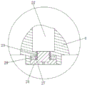
图6是图5的A部的放大图;Fig. 6 is an enlarged view of A part of Fig. 5;
图7是窗盖仅能遮盖一个清洗窗的结构示意图;Fig. 7 is the structural representation that the window cover can only cover one cleaning window;
图8是窗盖能够同时遮盖两个清洗窗的结构示意图;Figure 8 is a schematic structural diagram of a window cover capable of covering two cleaning windows at the same time;
图9是喷洒头前端设有扁平开口时的结构示意图;9 is a schematic structural diagram when the front end of the sprinkler is provided with a flat opening;
图10是喷洒头前端设有扁平扩增口时的结构示意图。FIG. 10 is a schematic structural diagram when a flat expansion port is provided at the front end of the sprinkler head.
具体实施方式Detailed ways
下面结合附图和具体实施方式对本发明作进一步详细的说明:The present invention will be described in further detail below in conjunction with the accompanying drawings and specific embodiments:
请参阅图1至图10,本发明提供一种发泡枪,包括枪体1、设于枪体1前端的枪管2以及设于枪体1尾端下方的枪柄3,枪体1上设有与枪柄3相匹配的扳机4,枪管2前端设有枪嘴5,枪管2内设有与枪嘴5相匹配的顶杆6,枪体1上方设有连接头7,连接头7连接有发泡罐8,所述连接头7连接有若干爪接头9;所述爪接头9下表面中心设有一与连接头7相匹配的螺纹部10;所述爪接头9上表面中部设有一凹槽11,凹槽11槽底设有一与螺纹部10相贯通的适配管12;所述爪接头9上表面边沿设有若干呈圆周均匀分布的卡爪13;所述卡爪13与爪接头9上表面之间形成一卡槽14,相邻的卡爪13之间具有与卡槽14相贯通的卡入间隙15;所述发泡罐8下端设有一与凹槽11相匹配的安装头16;所述安装头16外周面设有若干与卡爪13个数相对应的旋转卡板17,旋转卡板17的宽度小于卡入间隙15的宽度,旋转卡板17的厚度小于卡槽14的槽高;所述安装头16下表面中心设有与适配管12相匹配的对接孔18。Please refer to FIGS. 1 to 10 , the present invention provides a foaming gun, comprising a gun body 1 , a gun barrel 2 arranged at the front end of the gun body 1 , and a gun handle 3 arranged below the rear end of the gun body 1 . There is a trigger 4 that matches the handle 3, the front end of the barrel 2 is provided with a
所述枪管2一侧外壁上设有若干均匀分布的清理窗19;所述清理窗19上盖合有与其相匹配的窗盖20,窗盖20通过紧固螺丝21固定于枪管2上;所述枪体1内设有与连接头7相贯通的进料腔22,枪体1一侧外壁设有与进料腔22相贯通的清理孔23;所述清理孔23螺接有密封螺丝24。The outer wall of one side of the barrel 2 is provided with a number of evenly distributed cleaning windows 19; the cleaning window 19 is covered with a
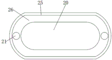
所述窗盖20与清理窗19相对的一侧侧壁设有一密封槽25;所述密封槽25内设有与其相匹配的密封圈26。The side wall of the
所述清理孔23下端孔口设有一卡位台阶27,密封螺丝24的头部卡于卡位台阶27上;所述密封螺丝24的头部与卡位台阶27之间设有一密封垫片28。The opening of the lower end of the
所述枪嘴5前端设有喷洒头29;所述喷洒头29前端端面设有一扁平开口30或扁平扩增口31,扁平扩增口31横截面呈前宽后窄的三角状。The front end of the
所述连接头7螺接有第一螺接头32,第一螺接头32连接有第一软管33;所述第一软管33端部连接有一快速接头34;所述快速接头34上设有一主接口35以及至少两个以上的分接口36,主接口35与第一软管33相连接,分接口36连接有第二软管37;所述第二软管37端部连接有第二螺接头38,爪接头9通过螺纹部10与第二螺接头38相螺接。The connecting head 7 is screwed with a first screw joint 32, and the first screw joint 32 is connected with a first hose 33; the end of the first hose 33 is connected with a quick joint 34; the quick joint 34 is provided with a The
所述爪接头9上表面与卡爪13外壁之间通过一呈弧状的导向面39过渡连接。An arc-shaped
本发明的使用方法如下:The using method of the present invention is as follows:
当发泡罐要与发泡枪进行连接时,可握住发泡罐将发泡罐的安装头上的旋转卡板17对准爪接头9的卡入间隙15位置,然后下移,使旋转卡板17进入至卡入间隙15内并下移至与卡槽14槽口齐平的位置,紧接着便可以适配管12为中心对旋转卡板17进行旋转,使旋转卡板17通过卡槽14槽口旋转至进入至卡槽14内,当旋转卡板17进入卡槽14内后,卡槽14便会对旋转卡板17的位置进行限制,从而对发泡罐的安装头16位置进行限制,实现发泡枪与发泡管之间的紧固连接,由此可知,只需将旋转卡板17通过卡入间隙15下移至与卡槽14槽口齐平的位置,再将旋转卡板17旋转至与卡入间隙15相贯通的卡槽14内,便能够实现发泡枪与发泡罐之间的固定,这种旋转动作极小,只需一下便能够快速完成,连接效率远超螺纹连接需要旋转许多圈才能完成紧固的情况,从而实现发泡枪与发泡罐之间的快速连接。When the foaming tank is to be connected with the foaming gun, hold the foaming tank and align the
当发泡枪与发泡罐完成连接时,适配管12已插入至安装头16的对接孔18内,完成了适配管12与对接孔18之间的对接,而在实际使用过程中,适配管12内则会安装普通的气阀,当对接孔18与适配管12进行对接时,对接孔18内的顶针则会将气阀顶开,此时发泡罐内的发泡料便能够通过适配管12以及螺纹部10进入至枪体的进料腔22内,当需要进行喷涂工作时,只需按压扳机4,便能够控制顶杆6将枪嘴5打开实现喷涂。When the connection between the foaming gun and the foaming tank is completed, the
当工作人员需要对枪管2内残留的固化发泡料进行清理时,只需将紧固螺丝21旋出,便能够将窗盖20从清理窗19上取下,当清理窗19暴露时,工作人员便可透过清理窗19直接对枪管2内部进行清理,无需将枪管2从枪体上完全拆卸下来进行清理,当枪管2内部清理完成后,再通过紧固螺丝21将窗盖20固定于枪管2上即可,而密封圈26的存在能够有效提高窗盖20与清理窗19之间的密封性,有效避免进入枪管2内的发泡料通过清理窗19发生泄漏的情况。When the staff needs to clean the solidified foam material remaining in the barrel 2, the
当工作人员需要对进料腔22内残留的固化发泡料进行清理时,则可将密封螺丝24从清理孔内旋出,当密封螺丝24旋出后,工作人员便可通过清理孔23直接对进料腔22进行清理,无需对安装在枪体1上的其他部件进行拆卸,减少了清理的麻烦,当进料腔22清理完成后,再将密封螺丝24旋紧于清理孔23内即可,而密封垫片28的存在能够有效提高密封螺丝24头部与卡位台阶27之间的密封性,从而保证清理孔23的密封性,有效避免进料腔22的发泡料通过清理孔23发生泄漏的情况。When the staff needs to clean the solidified foaming material remaining in the
当喷洒头29前端端面设有扁平开口时,一旦发泡料从喷洒头29喷出,发泡料则会首先经过扁平开口,扁平开口30则会对发泡料进行压缩,从条状转变成被压缩的扁平状,由于扁平开口30不止前端敞开,两侧同样敞开,因此经过扁平开口30的发泡料则会散开,从扁平状转变成前宽后窄的扇形扁平状,从而实现发泡料喷涂范围的增大;当喷洒头29前端端面设有扁平扩增口31时,从喷洒头29内喷出的发泡料则会顺着扁平扩增口31轨迹散开,而扁平扩增口31横截面呈前宽后窄的三角状,扁平扩增口31前端孔口以及两侧皆敞开,因此最终经过扁平扩增口31的发泡料则会从条状转变成扇形扁平状,而扁平开口30形成的扇形角度则大于扁平扩增口31的扇形角度,工作人员可根据实际所需选择相应的喷洒头29,且无论扁平开口30或是扁平扩增口31皆可起到扩增发泡料喷涂范围的增大,有效提高喷涂效率,而喷洒头29与枪嘴之间并非一体结构,相当于喷洒头29有一处台阶卡于枪嘴5嘴口位置,然后利用枪嘴5与枪管2前端的螺接将该处台阶卡于枪嘴5嘴口位置,从而实现枪嘴5与喷洒头29之间的固定,因此只需松动枪嘴5,便能够对喷洒头29进行旋转,从而起到改变扁平开口与扁平扩增口的角度,无需通过改变整个枪体的角度来改变扁平开口与扁平扩增口的角度,利于喷涂工作的进行。When the front end face of the spraying
连接头7螺接有第一螺接头32,第一螺接头32连接有第一软管33,第一软管33端部连接有快速接头34,快速接头34上设有一主接口35以及至少两个以上的分接口36,主接口35与第一软管33相连接,分接口36连接有第二软管37,第二软管37端部连接有第二螺接头38,爪接头9通过螺纹部10与第二螺接头38相螺接,当多个爪接头9需要与多个发泡罐上的安装头16进行连接时,只需将旋转卡板17卡入爪接头9上的卡槽即可,由于爪接头9与旋转卡板17之间的连接只需旋转较小的角度便能完成,因此与爪接头9相连接的第二软管37仅会出现极小幅度的扭曲,不仅不会影响爪接头9与发泡罐的安装头之间的连接效率,且软管扭曲变形的角度有限,不会影响第二软管37对发泡料的输送,有效避免由于第二软管37扭曲变形过度导致内部堵塞无法流通的情况。The connecting head 7 is screwed with a first screw joint 32, the first screw joint 32 is connected with a first hose 33, the end of the first hose 33 is connected with a
爪接头9上表面与卡爪13外壁之间通过一呈弧状的导向面39过渡连接,导向面39的存在可进一步提高旋转卡板17卡入卡槽14内的效率,当旋转卡板17在进入卡入间隙15时,无须完全对准,若是旋转卡板17由于未与卡入间隙15对准与导向面发生碰撞时,导向面39便会通过自身光滑的弧面快速将旋转卡板17导入之卡槽槽口位置,不会出现卡入动作滞塞的情况,有效提高旋转卡板17与卡爪13卡接时的效率。The upper surface of the claw joint 9 and the outer wall of the
Claims (7)
- The foaming gun comprises a gun body, a gun barrel arranged at the front end of the gun body and a gun handle arranged below the tail end of the gun body, wherein a trigger matched with the gun handle is arranged on the gun body, a gun nozzle is arranged at the front end of the gun barrel, a push rod matched with the gun nozzle is arranged in the gun barrel, a connector is arranged above the gun body and connected with a foaming tank, the foaming gun is characterized in that a plurality of claw joints are connected with the connector, threaded parts matched with the connector are arranged in the centers of the lower surfaces of the claw joints, grooves are formed in the middles of the upper surfaces of the claw joints, adapting pipes communicated with the threaded parts are arranged at the bottoms of the grooves, a plurality of clamping jaws uniformly distributed in the circumference are arranged on the edges of the upper surfaces of the claw joints, clamping grooves are formed between the clamping jaws and the upper surfaces of the claw joints, clamping gaps communicated with the clamping grooves are formed between adjacent clamping jaws, matched with the grooves are arranged at the lower end of the foaming tank, a plurality of rotating clamping plates corresponding to the number are arranged on the outer circumferential surface of the mounting.
- 2. The kinds of foam guns as claimed in claim 1, wherein the barrel has a plurality of cleaning windows uniformly distributed on its outer wall, the cleaning windows are covered with a window cover matching with the cleaning windows, the window cover is fixed on the barrel by fastening screws, the gun body has a feeding cavity communicated with the connector, the outer wall of the gun body has a cleaning hole communicated with the feeding cavity, and the cleaning hole is screwed with a sealing screw.
- 3. The foam gun as claimed in claim 2, wherein sealing groove is provided on the side wall of the window cover opposite to the cleaning window, and a sealing ring matching with the sealing groove is provided in the sealing groove.
- 4. The kinds of foam guns as claimed in claim 2, wherein the lower opening of the cleaning hole has retaining steps, the head of the sealing screw is retained on the retaining steps, and sealing gasket is disposed between the head of the sealing screw and the retaining steps.
- 5. The kinds of foaming gun as claimed in claim 1, wherein the front end of the nozzle is provided with a spray head, the front end face of the spray head is provided with flat openings or flat enlarged openings, and the cross section of the flat enlarged openings is triangular with a wide front and a narrow back.
- 6. The foam gun according to claim 1, wherein the connector is screwed with a screw joint, a hose is connected with a screw joint, the end of the hose is connected with a quick joint, the quick joint is provided with a main joint and at least two sub-joints, the main joint is connected with the hose, the sub-joints are connected with a second hose, the end of the second hose is connected with a second screw joint, and the claw joint is screwed with the second screw joint through a screw thread.
- 7. The kinds of foaming gun as claimed in claim 1, wherein the transition connection between the upper surface of the jaw joint and the outer wall of the jaw is formed by arc-shaped guide surfaces.
Priority Applications (1)
| Application Number | Priority Date | Filing Date | Title |
|---|---|---|---|
| CN201911247331.4A CN110732425A (en) | 2019-12-09 | 2019-12-09 | kinds of foaming gun |
Applications Claiming Priority (1)
| Application Number | Priority Date | Filing Date | Title |
|---|---|---|---|
| CN201911247331.4A CN110732425A (en) | 2019-12-09 | 2019-12-09 | kinds of foaming gun |
Publications (1)
| Publication Number | Publication Date |
|---|---|
| CN110732425A true CN110732425A (en) | 2020-01-31 |
Family
ID=69274464
Family Applications (1)
| Application Number | Title | Priority Date | Filing Date |
|---|---|---|---|
| CN201911247331.4A Pending CN110732425A (en) | 2019-12-09 | 2019-12-09 | kinds of foaming gun |
Country Status (1)
| Country | Link |
|---|---|
| CN (1) | CN110732425A (en) |
Cited By (2)
| Publication number | Priority date | Publication date | Assignee | Title |
|---|---|---|---|---|
| CN115605411A (en) * | 2020-05-15 | 2023-01-13 | 阿尔塔谢姆股份有限公司(Be) | Basket |
| CN116809265A (en) * | 2023-07-17 | 2023-09-29 | 台州市洛克赛工具有限公司 | Spray gun capable of rapidly disassembling storage tank and connecting method |
Citations (15)
| Publication number | Priority date | Publication date | Assignee | Title |
|---|---|---|---|---|
| US2985386A (en) * | 1958-07-18 | 1961-05-23 | William F Steinen | Spray nozzle |
| US4618101A (en) * | 1983-11-25 | 1986-10-21 | Piggott Richard G | Spray nozzle |
| US5464154A (en) * | 1993-09-29 | 1995-11-07 | Union Carbide Chemicals & Plastics Technology Corporation | Methods for spraying polymeric compositions with compressed fluids and enhanced atomization |
| CN1187150A (en) * | 1995-07-07 | 1998-07-08 | 普罗克特和甘保尔公司 | Pump sprayer for viscous or solid laden liquids |
| CN201067712Y (en) * | 2007-07-26 | 2008-06-04 | 郑州新长城房地产有限公司 | Foamed glue spray gun spray head |
| CN201353534Y (en) * | 2009-01-07 | 2009-12-02 | 上海伊斯泰橡塑制品有限公司 | Low pressure nozzle |
| CN201475560U (en) * | 2009-07-01 | 2010-05-19 | 江春宝 | Improved Structure of Pipe Joints |
| US20130221130A1 (en) * | 2002-10-24 | 2013-08-29 | 3M Innovative Properties Company | Spraygun with built-in quick-fit connector |
| CN203363493U (en) * | 2013-07-06 | 2013-12-25 | 芜湖华夏科技安防有限责任公司 | High-pressure fire hose connector |
| CN103741957A (en) * | 2013-12-27 | 2014-04-23 | 深圳市富诚幕墙装饰工程有限公司 | Integrated type high-pressure spray gun |
| CN105642471A (en) * | 2016-04-06 | 2016-06-08 | 李加祥 | Foaming gun |
| CN107606356A (en) * | 2017-09-05 | 2018-01-19 | 无锡市永兴金属软管有限公司 | It is a kind of can Fast Installation or dismounting metal hose joint |
| CN109641234A (en) * | 2016-06-03 | 2019-04-16 | 维塔利·伊万诺维奇·蒂托洛夫 | System for dispensing sprayable foamable products |
| CN109869560A (en) * | 2018-08-19 | 2019-06-11 | 赵建雄 | A small size quick-plug connector |
| CN211160315U (en) * | 2019-12-09 | 2020-08-04 | 李珍奕 | Foaming gun |
-
2019
- 2019-12-09 CN CN201911247331.4A patent/CN110732425A/en active Pending
Patent Citations (15)
| Publication number | Priority date | Publication date | Assignee | Title |
|---|---|---|---|---|
| US2985386A (en) * | 1958-07-18 | 1961-05-23 | William F Steinen | Spray nozzle |
| US4618101A (en) * | 1983-11-25 | 1986-10-21 | Piggott Richard G | Spray nozzle |
| US5464154A (en) * | 1993-09-29 | 1995-11-07 | Union Carbide Chemicals & Plastics Technology Corporation | Methods for spraying polymeric compositions with compressed fluids and enhanced atomization |
| CN1187150A (en) * | 1995-07-07 | 1998-07-08 | 普罗克特和甘保尔公司 | Pump sprayer for viscous or solid laden liquids |
| US20130221130A1 (en) * | 2002-10-24 | 2013-08-29 | 3M Innovative Properties Company | Spraygun with built-in quick-fit connector |
| CN201067712Y (en) * | 2007-07-26 | 2008-06-04 | 郑州新长城房地产有限公司 | Foamed glue spray gun spray head |
| CN201353534Y (en) * | 2009-01-07 | 2009-12-02 | 上海伊斯泰橡塑制品有限公司 | Low pressure nozzle |
| CN201475560U (en) * | 2009-07-01 | 2010-05-19 | 江春宝 | Improved Structure of Pipe Joints |
| CN203363493U (en) * | 2013-07-06 | 2013-12-25 | 芜湖华夏科技安防有限责任公司 | High-pressure fire hose connector |
| CN103741957A (en) * | 2013-12-27 | 2014-04-23 | 深圳市富诚幕墙装饰工程有限公司 | Integrated type high-pressure spray gun |
| CN105642471A (en) * | 2016-04-06 | 2016-06-08 | 李加祥 | Foaming gun |
| CN109641234A (en) * | 2016-06-03 | 2019-04-16 | 维塔利·伊万诺维奇·蒂托洛夫 | System for dispensing sprayable foamable products |
| CN107606356A (en) * | 2017-09-05 | 2018-01-19 | 无锡市永兴金属软管有限公司 | It is a kind of can Fast Installation or dismounting metal hose joint |
| CN109869560A (en) * | 2018-08-19 | 2019-06-11 | 赵建雄 | A small size quick-plug connector |
| CN211160315U (en) * | 2019-12-09 | 2020-08-04 | 李珍奕 | Foaming gun |
Cited By (2)
| Publication number | Priority date | Publication date | Assignee | Title |
|---|---|---|---|---|
| CN115605411A (en) * | 2020-05-15 | 2023-01-13 | 阿尔塔谢姆股份有限公司(Be) | Basket |
| CN116809265A (en) * | 2023-07-17 | 2023-09-29 | 台州市洛克赛工具有限公司 | Spray gun capable of rapidly disassembling storage tank and connecting method |
Similar Documents
| Publication | Publication Date | Title |
|---|---|---|
| CN110252535B (en) | Foam, water spray switching device and foam and water spray dual-purpose integrated spray head | |
| CN1261825A (en) | Dual mode reversible tip seal | |
| CN119951685A (en) | Spray applicator with fixed mixing chamber | |
| CN108970909A (en) | Pipeline special glue nozzle | |
| CN110694819B (en) | A color-changing valve island for a multifunctional manipulator | |
| CN107051794B (en) | Fluid micro-injection device and flow channel assembly thereof | |
| CN211160315U (en) | Foaming gun | |
| CN201108875Y (en) | a nozzle | |
| KR20130100435A (en) | Plugging jig for hull block leakage test | |
| CN110124919A (en) | A kind of multicomponent paint spray device | |
| CN221461728U (en) | Mortar spraying gun | |
| CN211190666U (en) | Color-changing valve terminal for multifunctional manipulator | |
| CN118831746A (en) | Spray gun head and spray gun | |
| CN221268576U (en) | Anti-blocking spray head for spray painting of washing machine panel | |
| CN221869053U (en) | A glue gun head assembly for high viscosity materials | |
| CN210637661U (en) | Blowing air bag | |
| CN207507684U (en) | A kind of nozzle assembly of reverse cleaning type airless spraying rifle | |
| CN107638979B (en) | Spraying assembly | |
| CN220346188U (en) | High-pressure water spray pipe | |
| CN110594513A (en) | a blown bag | |
| CN222202984U (en) | A pneumatic injection filling valve | |
| CN222874273U (en) | Sand blasting gun head | |
| CN220608954U (en) | Water hose extension device | |
| CN223145059U (en) | High-efficient waterproof coating automatic spraying device | |
| CN222751088U (en) | An irrigation device |
Legal Events
| Date | Code | Title | Description |
|---|---|---|---|
| PB01 | Publication | ||
| PB01 | Publication | ||
| SE01 | Entry into force of request for substantive examination | ||
| SE01 | Entry into force of request for substantive examination | ||
| RJ01 | Rejection of invention patent application after publication |
Application publication date: 20200131 |
|
| RJ01 | Rejection of invention patent application after publication |