CN110762902A - Micro-channel evaporator and air conditioning system - Google Patents
Micro-channel evaporator and air conditioning system Download PDFInfo
- Publication number
- CN110762902A CN110762902A CN201810836723.3A CN201810836723A CN110762902A CN 110762902 A CN110762902 A CN 110762902A CN 201810836723 A CN201810836723 A CN 201810836723A CN 110762902 A CN110762902 A CN 110762902A
- Authority
- CN
- China
- Prior art keywords
- flat tube
- shaped body
- microchannel evaporator
- flat
- group
- Prior art date
- Legal status (The legal status is an assumption and is not a legal conclusion. Google has not performed a legal analysis and makes no representation as to the accuracy of the status listed.)
- Pending
Links
Images


Classifications
-
- F—MECHANICAL ENGINEERING; LIGHTING; HEATING; WEAPONS; BLASTING
- F25—REFRIGERATION OR COOLING; COMBINED HEATING AND REFRIGERATION SYSTEMS; HEAT PUMP SYSTEMS; MANUFACTURE OR STORAGE OF ICE; LIQUEFACTION SOLIDIFICATION OF GASES
- F25B—REFRIGERATION MACHINES, PLANTS OR SYSTEMS; COMBINED HEATING AND REFRIGERATION SYSTEMS; HEAT PUMP SYSTEMS
- F25B41/00—Fluid-circulation arrangements
- F25B41/30—Expansion means; Dispositions thereof
- F25B41/37—Capillary tubes
-
- F—MECHANICAL ENGINEERING; LIGHTING; HEATING; WEAPONS; BLASTING
- F25—REFRIGERATION OR COOLING; COMBINED HEATING AND REFRIGERATION SYSTEMS; HEAT PUMP SYSTEMS; MANUFACTURE OR STORAGE OF ICE; LIQUEFACTION SOLIDIFICATION OF GASES
- F25B—REFRIGERATION MACHINES, PLANTS OR SYSTEMS; COMBINED HEATING AND REFRIGERATION SYSTEMS; HEAT PUMP SYSTEMS
- F25B39/00—Evaporators; Condensers
- F25B39/02—Evaporators
-
- F—MECHANICAL ENGINEERING; LIGHTING; HEATING; WEAPONS; BLASTING
- F24—HEATING; RANGES; VENTILATING
- F24F—AIR-CONDITIONING; AIR-HUMIDIFICATION; VENTILATION; USE OF AIR CURRENTS FOR SCREENING
- F24F13/00—Details common to, or for air-conditioning, air-humidification, ventilation or use of air currents for screening
- F24F13/30—Arrangement or mounting of heat-exchangers
-
- F—MECHANICAL ENGINEERING; LIGHTING; HEATING; WEAPONS; BLASTING
- F25—REFRIGERATION OR COOLING; COMBINED HEATING AND REFRIGERATION SYSTEMS; HEAT PUMP SYSTEMS; MANUFACTURE OR STORAGE OF ICE; LIQUEFACTION SOLIDIFICATION OF GASES
- F25B—REFRIGERATION MACHINES, PLANTS OR SYSTEMS; COMBINED HEATING AND REFRIGERATION SYSTEMS; HEAT PUMP SYSTEMS
- F25B2500/00—Problems to be solved
- F25B2500/05—Cost reduction
Landscapes
- Engineering & Computer Science (AREA)
- Mechanical Engineering (AREA)
- General Engineering & Computer Science (AREA)
- Physics & Mathematics (AREA)
- Thermal Sciences (AREA)
- Chemical & Material Sciences (AREA)
- Combustion & Propulsion (AREA)
- Heat-Exchange Devices With Radiators And Conduit Assemblies (AREA)
Abstract
本发明涉及制冷技术领域,公开了一种微通道蒸发器及一种空调系统,以降低生产成本,并且提升制冷能效。微通道蒸发器包括:位于空调系统中风量不同的位置的至少两片扁管组,每片扁管组包括进液集流管和出液集流管以及连接于进液集流管和出液集流管之间的一组扁管,进液集流管内插设有分配管,分配管沿轴向开设有若干个通孔;分配器,包括进液口以及与每片扁管组对应的出液口;与至少两片扁管组分别对应的毛细管,每根毛细管用于将与其对应的扁管组的分配管与出液口连接;水盘,位于至少两片扁管组的底部;其中,对应不同扁管组的毛细管根据扁管组所处位置的风量大小不同而选择不同尺寸。
The invention relates to the technical field of refrigeration, and discloses a microchannel evaporator and an air conditioning system, so as to reduce production cost and improve refrigeration energy efficiency. The micro-channel evaporator includes: at least two flat tube groups located at positions with different air volumes in the air conditioning system, each flat tube group includes a liquid inlet header and a liquid outlet header and is connected to the liquid inlet header and the liquid outlet. A group of flat tubes between the headers, the liquid inlet header is inserted with a distribution tube, and the distribution tube is provided with a number of through holes along the axial direction; the distributor includes the liquid inlet and the corresponding flat tube group for each piece. a liquid outlet; capillaries corresponding to at least two flat tube groups respectively, each capillary is used to connect the distribution pipe of the corresponding flat tube group with the liquid outlet; a water pan, located at the bottom of the at least two flat tube groups; Wherein, different sizes of capillaries corresponding to different flat tube groups are selected according to different air volumes at the positions where the flat tube groups are located.
Description
技术领域technical field
本发明涉及制冷技术领域,特别是涉及一种微通道蒸发器及一种空调系统。The invention relates to the technical field of refrigeration, in particular to a microchannel evaporator and an air conditioning system.
背景技术Background technique
列间空调多应用于模块化机房中,主要通过蒸汽压缩直接膨胀的方式进行制冷,制冷剂在压缩机、冷凝器、节流元件和蒸发器顺序连接形成的封闭管路中循环,具体过程为:冷媒通过压缩机被压缩成高温高压气体后进入冷凝器,在冷凝器内冷凝放热成低温高压液体,再经过节流元件节流成低温低压液体,然后进入蒸发器进行蒸发换热,蒸发后的制冷剂气体回到压缩机中完成一次循环。其中,列间空调的蒸发器通常使用较为传统的铜管翅片式蒸发器。In-row air conditioners are mostly used in modular computer rooms, and are mainly cooled by vapor compression and direct expansion. The refrigerant circulates in the closed pipeline formed by the sequential connection of the compressor, condenser, throttling element and evaporator. The specific process is as follows: : The refrigerant is compressed into high temperature and high pressure gas by the compressor and then enters the condenser, condenses and releases heat in the condenser into low temperature and high pressure liquid, and then is throttled into low temperature and low pressure liquid through the throttling element, and then enters the evaporator for evaporative heat exchange and evaporation. The latter refrigerant gas is returned to the compressor to complete a cycle. Among them, the evaporator of the inter-column air conditioner usually uses a more traditional copper tube fin evaporator.
如图1所示,现有的铜管翅片式蒸发器的结构包括换热铜管01和包覆于换热铜管外表面的翅片,为了达到较大的换热量,蒸发器会设置多排换热铜管01,这样一方面会增加生产成本,另一方面,排布较为密集的换热铜管01也会增加风阻,影响空调机组的换热效率。As shown in FIG. 1, the structure of the existing copper tube fin type evaporator includes heat
发明内容SUMMARY OF THE INVENTION
本发明实施例提供了一种微通道蒸发器及一种空调系统,以降低生产成本,并且提升制冷能效。Embodiments of the present invention provide a microchannel evaporator and an air conditioning system, so as to reduce production costs and improve refrigeration energy efficiency.
本发明实施例提供了一种微通道蒸发器,包括:An embodiment of the present invention provides a microchannel evaporator, comprising:
位于空调系统中风量不同的位置的至少两片扁管组,每片所述扁管组包括进液集流管和出液集流管以及连接于进液集流管和出液集流管之间的一组扁管,所述进液集流管内插设有分配管,所述分配管沿轴向开设有若干个通孔;At least two flat tube groups located at positions with different air volumes in the air conditioning system, each flat tube group includes a liquid inlet header and a liquid outlet header and is connected to the liquid inlet header and the outlet header. A group of flat tubes between them, a distribution tube is inserted in the liquid inlet header, and the distribution tube is provided with a number of through holes along the axial direction;
分配器,包括进液口以及与每片扁管组对应的出液口;The distributor, including the liquid inlet and the liquid outlet corresponding to each flat tube group;
与所述至少两片扁管组分别对应的毛细管,每根所述毛细管用于将与其对应的扁管组的分配管与所述出液口连接;Capillaries corresponding to the at least two flat tube groups respectively, each of the capillaries is used to connect the distribution pipe of the corresponding flat tube group with the liquid outlet;
水盘,位于所述至少两片扁管组的底部;a water tray, located at the bottom of the at least two flat tube groups;
其中,对应不同扁管组的毛细管根据扁管组所处位置的风量大小不同而选择不同尺寸。Wherein, different sizes of capillaries corresponding to different flat tube groups are selected according to the size of the air volume at the positions where the flat tube groups are located.
在一个具体的实施方式中,位于风量较大的位置处的扁管组的毛细管内径大于位于风量较小的位置处的扁管组的毛细管内径。In a specific embodiment, the inner diameter of the capillary tube of the flat tube group located at the position where the air volume is larger is larger than the inner diameter of the capillary tube of the flat tube group located at the position where the air volume is smaller.
在一个具体的实施方式中,位于风量较大的位置处的扁管组的毛细管长度小于位于风量较小的位置处的扁管组的毛细管长度。In a specific embodiment, the capillary length of the flat tube group located at the position where the air volume is larger is smaller than the capillary length of the flat tube group located at the position where the air volume is smaller.
在一个具体的实施方式中,对于每片扁管组,位于风量较大的区域内的分配管上通孔的分布密度小于位于风量较小的区域内的分配管上通孔的分布密度。In a specific embodiment, for each flat tube group, the distribution density of the through holes on the distribution pipe located in the area with a large air volume is smaller than the distribution density of the through holes on the distribution pipe located in the area with a small air volume.
在一个具体的实施方式中,所述扁管组的数量为两片,且所述两片扁管组呈V形体设置,所述V形体的开口形成所述微通道蒸发器的出风口。In a specific embodiment, the number of the flat tube groups is two, and the two flat tube groups are arranged in a V-shaped body, and the opening of the V-shaped body forms the air outlet of the micro-channel evaporator.
在一个具体的实施方式中,所述扁管组的数量为四片,每两片扁管组分别呈第一V形体设置与第二V形体设置,且所述第二V形体叠置于所述第一V形体之上,所述第一V形体的开口与所述第二V形体的开口形成所述微通道蒸发器的出风口。In a specific embodiment, the number of the flat tube groups is four, each two flat tube groups are arranged in a first V-shaped body and a second V-shaped body respectively, and the second V-shaped body is stacked on the Above the first V-shaped body, the opening of the first V-shaped body and the opening of the second V-shaped body form the air outlet of the micro-channel evaporator.
在一个具体的实施方式中,所述水盘的数量为两个,分别为中水盘和下水盘,所述中水盘位于所述第二V形体与所述第一V形体之间,所述下水盘位于所述第一V形体底部。In a specific embodiment, the number of the water pans is two, which are a middle water pan and a lower water pan, and the middle water pan is located between the second V-shaped body and the first V-shaped body, so The drain pan is located at the bottom of the first V-shaped body.
在本发明实施例中,液态冷媒进入分配器后经过与分配器的各个出液口连接的毛细管送入不同的扁管组,由于各片扁管组所处位置的风量的不同的,因此针对不同的扁管组,通过将与其对应的毛细管设计为不同的尺寸,就可以控制实际进入扁管组内的冷媒流量,这样一方面保证了位于风量较大的位置处的扁管组内的冷媒流量能够满足其换热需求,另一方面又避免了位于风量较小的位置处的扁管组内的冷媒过多造成浪费,相比现有技术中的铜管翅片式蒸发器,本发明实施例提供的微通道蒸发器不仅生产成本较低,而且制冷能效也大大提升。In the embodiment of the present invention, after the liquid refrigerant enters the distributor, it is sent to different flat tube groups through capillaries connected to the various liquid outlets of the distributor. Different flat tube groups can control the flow of refrigerant that actually enters the flat tube group by designing the corresponding capillaries to have different sizes. The flow rate can meet its heat exchange requirements, and on the other hand, it avoids waste caused by too much refrigerant in the flat tube group located at a position where the air volume is small. Compared with the copper tube fin evaporator in the prior art, the present invention The microchannel evaporator provided by the embodiment not only has lower production cost, but also greatly improves the cooling energy efficiency.
本发明实施例还提供了一种空调系统,包括通过管路顺序连接形成封闭循环的压缩机、冷凝器、节流元件以及如前述任一技术方案所述的微通道蒸发器,其中,所述节流元件与所述微通道蒸发器的分配器的进液口连接,所述压缩机与所述微通道蒸发器的出液集流管连接。该空调系统具有较高的制冷能效。An embodiment of the present invention further provides an air-conditioning system, comprising a compressor, a condenser, a throttling element and a micro-channel evaporator according to any of the foregoing technical solutions, which are sequentially connected through pipelines to form a closed cycle, wherein the The throttling element is connected with the liquid inlet of the distributor of the microchannel evaporator, and the compressor is connected with the liquid outlet collecting pipe of the microchannel evaporator. The air conditioning system has high cooling energy efficiency.
在一个具体的实施方式中,所述节流元件为电子膨胀阀;或者,所述节流元件为热力膨胀阀。In a specific embodiment, the throttling element is an electronic expansion valve; or, the throttling element is a thermal expansion valve.
附图说明Description of drawings
图1为现有技术中的铜管翅片式蒸发器的结构示意图;Fig. 1 is the structural representation of the copper tube fin type evaporator in the prior art;
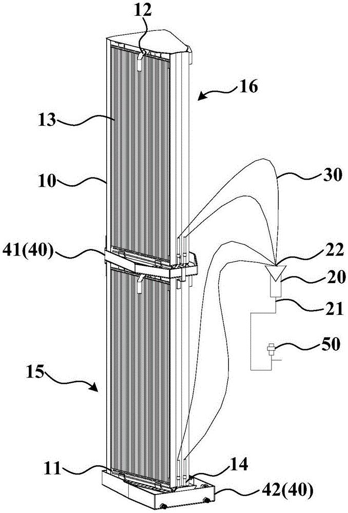
图2为本发明实施例微通道蒸发器的结构示意图。FIG. 2 is a schematic structural diagram of a microchannel evaporator according to an embodiment of the present invention.
附图标记:Reference number:
现有技术部分:Part of the prior art:
01-换热铜管01-Heat exchange copper tube
本发明实施例部分:Embodiments of the present invention:
10-扁管组 11-进液集流管 12-出液集流管 13-扁管10-Flat tube group 11-Inlet header 12-Outlet header 13-Flat tube
14-分配管 20-分配器 21-进液口 22-出液口14-Distribution pipe 20-Distributor 21-Liquid inlet 22-Liquid outlet
30-毛细管 40-水盘 15-第一V形体 16-第二V形体30-capillary 40-water tray 15-first V-shaped body 16-second V-shaped body
41-中水盘 42-下水盘 50-节流元件41-Middle water tray 42-Drain tray 50-Throttle element
具体实施方式Detailed ways
为了降低生产成本,并且提升制冷能效,本发明实施例提供了一种微通道蒸发器及一种空调系统。为使本发明的目的、技术方案和优点更加清楚,以下举实施例对本发明作进一步详细说明。In order to reduce production costs and improve refrigeration energy efficiency, embodiments of the present invention provide a microchannel evaporator and an air conditioning system. In order to make the objectives, technical solutions and advantages of the present invention clearer, the present invention will be further described in detail with reference to the following examples.
如图2所示,本发明实施例提供的微通道蒸发器,包括:As shown in FIG. 2, the microchannel evaporator provided in the embodiment of the present invention includes:
位于空调系统中风量不同的位置的至少两片扁管组10,每片扁管组10包括进液集流管11和出液集流管12以及连接于进液集流管11和出液集流管12之间的一组扁管13,进液集流管11内插设有分配管14,分配管14沿轴向开设有若干个通孔(图中未示出);At least two
分配器20,包括进液口21以及与每片扁管组10对应的出液口22;The
与至少两片扁管组10分别对应的毛细管30,每根毛细管30用于将与其对应的扁管组10的分配管14与出液口22连接;
水盘40,位于至少两片扁管组10的底部;The
其中,对应不同扁管组10的毛细管30根据扁管组10所处位置的风量大小不同而选择不同尺寸。Wherein, the
微通道蒸发器在工作时,液态冷媒经过毛细管30进入分配管14,由分配管14上开设的通孔喷入进液集流管11内,再然后由进液集流管11经过扁管13流至出液集流管12;与此同时,在位于微通道蒸发器的出风口前侧的风机的吸力作用下,外界热空气经过微通道蒸发器的扁管13并与扁管13内的液态冷媒发生热交换,在扁管13的表面形成冷凝水,冷凝水在重力所用下沿扁管13的表面流下,汇集在扁管组10下方的水盘40内。然而,由于空调机柜的内部结构较为紧凑,风机与微通道蒸发器的出风口之间形成的风道上不可避免地会被管路或者其它结构件所阻碍,这样就会导致不同扁管组10所在的位置的风量会有所差异,此时如果分配至每片扁管组10的冷媒流量是相同的,不仅会导致位于风量较大的位置处的扁管组10内的冷媒流量无法满足其换热需求,也会使得位于风量较小的位置处的扁管组10内冷媒过多造成浪费,从而影响制冷能效。When the micro-channel evaporator is in operation, the liquid refrigerant enters the distribution pipe 14 through the capillary 30, and is sprayed into the
在本发明实施例中,液态冷媒进入分配器20后经过与分配器20的各个出液口22连接的毛细管30送入不同的扁管组10,由于各片扁管组10所处位置的风量的不同的,因此针对不同的扁管组10,通过将与其对应的毛细管30设计为不同的尺寸,就可以控制实际进入扁管组10内的冷媒流量,这样一方面保证了位于风量较大的位置处的扁管组10内的冷媒流量能够满足其换热需求,另一方面又避免了位于风量较小的位置处的扁管组10内的冷媒过多造成浪费,相比现有技术中的铜管翅片式蒸发器,本发明实施例提供的微通道蒸发器不仅生产成本较低,而且制冷能效也大大提升。In the embodiment of the present invention, after the liquid refrigerant enters the
其中,扁管组的数量不限,在本发明的一个优选实施例中,扁管组的数量为两片,且两片扁管组呈V形体设置,V形体的开口形成微通道蒸发器的出风口,采用该实施例方案,可以降低列间空调蒸发器的高度,有利于冷凝水的排出。The number of flat tube groups is not limited. In a preferred embodiment of the present invention, the number of flat tube groups is two, and the two flat tube groups are arranged in a V-shaped body, and the opening of the V-shaped body forms the opening of the microchannel evaporator. For the air outlet, by adopting the solution of this embodiment, the height of the evaporator of the inter-column air conditioner can be reduced, which is beneficial to the discharge of condensed water.
更优的,如图1所示,扁管组10的数量为四片,每两片扁管组10分别呈第一V形体15设置与第二V形体16设置,且第二V形体16叠置于第一V形体15之上,第一V形体15的开口与第二V形体16的开口形成微通道蒸发器的出风口,相比现有技术中的整片式蒸发器,该方案可以进一步降低列间空调蒸发器的高度,并且明显增加了蒸发器的换热面积,从而提高换热效果。More preferably, as shown in FIG. 1 , the number of
上述实施例中的微通道蒸发器,可以在第一V形体15的下方设置一个水盘40,这样第一V形体15和第二V形体16热交换所产生的冷凝水均可在重力作用下汇聚到该水盘40内。为了使冷凝水更加便于排出,在本发明的优选实施例中,如图1所示,水盘40的数量为两个,分别为中水盘41和下水盘42,中水盘41位于第二V形体16与第一V形体15之间,下水盘42位于第一V形体15底部。In the microchannel evaporator in the above-mentioned embodiment, a
通过毛细管30的水量与其内径和长度有关,毛细管30的内径越小和/或长度越长,阻力越大,通过毛细管30的冷媒流量就越少;反之,毛细管30的内径越大和/或长度越短,阻力越小,通过毛细管30的冷媒流量就越多。因此,在本发明实施例中,可通过改变对应不同扁管组的毛细管内径和长度来调节分配至各个扁管组的冷媒流量。在一个具体的实施方式中,位于风量较大的位置处的扁管组10的毛细管30内径大于位于风量较小的位置处的扁管组10的毛细管30内径;在另一具体的实施方式中,位于风量较大的位置处的扁管组10的毛细管30长度小于位于风量较小的位置处的扁管组10的毛细管30长度。可以理解的,具体设置时,可以通过只改变毛细管30内径或者长度的其中一个参数来调节冷媒流量,当然也可以同时改变两个参数进行调节,本发明对此不做限制,只要保证经毛细管30调节后的冷媒流量能够在满足换热需求的同时又不会造成浪费即可。需要说明的是,毛细管30的具体尺寸需要扁管组10所处的空调系统中的风量进行设计,此处不作赘述。The amount of water passing through the
对于每片扁管组10,实际上扁管组10的不同区域所处的位置的风量也是不同的,因此也需要对扁管组10的不同区域扁管13的制冷剂流量进行调节。在实现本发明的过程中,发明人发现,分配管14上通孔的分布密度影响由集流管11送入扁管13的冷媒流量,具体表现为,分喷管14上通孔的分布密度越小,由集流管11送入风量较大区域扁管13的冷媒流量就越多,因此,在本发明实施例中,针对每片扁管组10,位于风量较大的区域内的分配管14上通孔的分布密度小于位于风量较小的区域内的分配管14上通孔的分布密度,这样就能使扁管组10的风量较大的区域的扁管13能够分配到更多的冷媒,保证换热效果。For each
本发明实施例还提供了一种空调系统,包括通过管路顺序连接形成封闭循环的压缩机、冷凝器、节流元件50以及如前述任一技术方案的微通道蒸发器,其中,节流元件50与微通道蒸发器的分配器20的进液口21连接,压缩机与微通道蒸发器的出液集流管12连接,其中,节流元件50具体可以为电子膨胀阀或者热力膨胀阀,本发明对此不做限制。该空调系统具有较高的制冷能效。The embodiment of the present invention also provides an air conditioning system, including a compressor, a condenser, a
显然,本领域的技术人员可以对本发明进行各种改动和变型而不脱离本发明的精神和范围。这样,倘若本发明的这些修改和变型属于本发明权利要求及其等同技术的范围之内,则本发明也意图包含这些改动和变型在内。It will be apparent to those skilled in the art that various modifications and variations can be made in the present invention without departing from the spirit and scope of the invention. Thus, provided that these modifications and variations of the present invention fall within the scope of the claims of the present invention and their equivalents, the present invention is also intended to include these modifications and variations.
Claims (9)
Priority Applications (2)
| Application Number | Priority Date | Filing Date | Title |
|---|---|---|---|
| CN201810836723.3A CN110762902A (en) | 2018-07-26 | 2018-07-26 | Micro-channel evaporator and air conditioning system |
| PCT/CN2019/086578 WO2020019828A1 (en) | 2018-07-26 | 2019-05-13 | Micro-channel evaporator and air-conditioning system |
Applications Claiming Priority (1)
| Application Number | Priority Date | Filing Date | Title |
|---|---|---|---|
| CN201810836723.3A CN110762902A (en) | 2018-07-26 | 2018-07-26 | Micro-channel evaporator and air conditioning system |
Publications (1)
| Publication Number | Publication Date |
|---|---|
| CN110762902A true CN110762902A (en) | 2020-02-07 |
Family
ID=69180863
Family Applications (1)
| Application Number | Title | Priority Date | Filing Date |
|---|---|---|---|
| CN201810836723.3A Pending CN110762902A (en) | 2018-07-26 | 2018-07-26 | Micro-channel evaporator and air conditioning system |
Country Status (2)
| Country | Link |
|---|---|
| CN (1) | CN110762902A (en) |
| WO (1) | WO2020019828A1 (en) |
Cited By (1)
| Publication number | Priority date | Publication date | Assignee | Title |
|---|---|---|---|---|
| CN111879035A (en) * | 2020-07-28 | 2020-11-03 | 西安交通大学 | Micro-channel evaporator and defrosting and re-frosting control method |
Families Citing this family (2)
| Publication number | Priority date | Publication date | Assignee | Title |
|---|---|---|---|---|
| CN117029262B (en) * | 2023-08-23 | 2025-03-25 | 西安交通大学 | A variable flow double-row microchannel heat exchanger and control method thereof |
| CN121655166B (en) * | 2026-02-06 | 2026-04-10 | 山东小鸭冷链有限公司 | Vehicle-mounted movable agricultural product efficient refrigerating device |
Citations (6)
| Publication number | Priority date | Publication date | Assignee | Title |
|---|---|---|---|---|
| CN101782297A (en) * | 2009-01-19 | 2010-07-21 | 三花丹佛斯(杭州)微通道换热器有限公司 | Heat exchanger |
| CN202792717U (en) * | 2012-09-04 | 2013-03-13 | 上海双桦汽车零部件股份有限公司 | All aluminum parallel flow evaporator |
| CN106152614A (en) * | 2014-07-11 | 2016-11-23 | 杭州三花研究院有限公司 | A kind of refrigeration system and heat exchanger thereof |
| CN206176826U (en) * | 2016-06-15 | 2017-05-17 | 艾默生网络能源有限公司 | Little channel evaporator and refrigerating system thereof |
| CN207455959U (en) * | 2017-06-30 | 2018-06-05 | 维谛技术有限公司 | Evaporator |
| CN208688035U (en) * | 2018-07-26 | 2019-04-02 | 维谛技术有限公司 | A kind of micro-channel evaporator and a kind of air-conditioning system |
Family Cites Families (9)
| Publication number | Priority date | Publication date | Assignee | Title |
|---|---|---|---|---|
| JP4506609B2 (en) * | 2005-08-08 | 2010-07-21 | 三菱電機株式会社 | Air conditioner and method of manufacturing air conditioner |
| CN102278908B (en) * | 2011-09-16 | 2013-06-26 | 四川长虹空调有限公司 | Microchannel heat exchanger |
| DE112013004284B4 (en) * | 2012-08-30 | 2022-11-24 | Shaoming Yu | Microchannel heat exchanger |
| CN105190202B (en) * | 2013-05-08 | 2017-11-17 | 三菱电机株式会社 | Heat exchanger and refrigerating circulatory device |
| CN103913019A (en) * | 2014-01-18 | 2014-07-09 | 胡洁 | High-performance micro-channel heat exchanger for refrigerating system |
| US10168083B2 (en) * | 2014-07-11 | 2019-01-01 | Hangzhou Sanhua Research Institute Co., Ltd. | Refrigeration system and heat exchanger thereof |
| CN204362491U (en) * | 2015-01-14 | 2015-05-27 | 北京雅驿欣科技有限公司 | Machine cabinet body and row between air-conditioning |
| CN204593813U (en) * | 2015-01-14 | 2015-08-26 | 深圳市艾特网能有限公司 | Between row heat exchanger of air conditioner and row between air-conditioning |
| CN206496415U (en) * | 2016-12-29 | 2017-09-15 | 艾尔维尔(上海)机房设备有限公司 | Air-conditioning between a kind of row of novel heat exchanger structure |
-
2018
- 2018-07-26 CN CN201810836723.3A patent/CN110762902A/en active Pending
-
2019
- 2019-05-13 WO PCT/CN2019/086578 patent/WO2020019828A1/en not_active Ceased
Patent Citations (6)
| Publication number | Priority date | Publication date | Assignee | Title |
|---|---|---|---|---|
| CN101782297A (en) * | 2009-01-19 | 2010-07-21 | 三花丹佛斯(杭州)微通道换热器有限公司 | Heat exchanger |
| CN202792717U (en) * | 2012-09-04 | 2013-03-13 | 上海双桦汽车零部件股份有限公司 | All aluminum parallel flow evaporator |
| CN106152614A (en) * | 2014-07-11 | 2016-11-23 | 杭州三花研究院有限公司 | A kind of refrigeration system and heat exchanger thereof |
| CN206176826U (en) * | 2016-06-15 | 2017-05-17 | 艾默生网络能源有限公司 | Little channel evaporator and refrigerating system thereof |
| CN207455959U (en) * | 2017-06-30 | 2018-06-05 | 维谛技术有限公司 | Evaporator |
| CN208688035U (en) * | 2018-07-26 | 2019-04-02 | 维谛技术有限公司 | A kind of micro-channel evaporator and a kind of air-conditioning system |
Non-Patent Citations (2)
| Title |
|---|
| 梁俊杰等: "制冷剂在蒸发器中的流量分配及分液管设计", 石油化工设备, vol. 33, no. 1, 31 January 2004 (2004-01-31), pages 30 - 33 * |
| 邢振禧主编: "《空气调节技术》", 31 August 1997, 中国商业出版社, pages: 71 - 87 * |
Cited By (2)
| Publication number | Priority date | Publication date | Assignee | Title |
|---|---|---|---|---|
| CN111879035A (en) * | 2020-07-28 | 2020-11-03 | 西安交通大学 | Micro-channel evaporator and defrosting and re-frosting control method |
| CN111879035B (en) * | 2020-07-28 | 2021-05-28 | 西安交通大学 | Microchannel evaporator and defrosting and refrost control method |
Also Published As
| Publication number | Publication date |
|---|---|
| WO2020019828A1 (en) | 2020-01-30 |
Similar Documents
| Publication | Publication Date | Title |
|---|---|---|
| CN111059802B (en) | Condensing device and air conditioning system having the same | |
| US10168083B2 (en) | Refrigeration system and heat exchanger thereof | |
| CN204438360U (en) | A kind of air-conditioner outdoor unit reducing filling quantity of refrigerant | |
| CN106288893A (en) | Heat exchanger system | |
| CN110762902A (en) | Micro-channel evaporator and air conditioning system | |
| CN105352225B (en) | Air conditioner | |
| CN102032719B (en) | Parallel flow heat-exchanging device for air conditioner | |
| JPH10205919A (en) | Chiller condenser | |
| CN211400388U (en) | Condensing equipment and air conditioning system who has it | |
| CN204943718U (en) | Heat-exchange system | |
| CN202835938U (en) | Condenser and air-conditioning outdoor machine | |
| CN206399049U (en) | Supercooled structure and air conditioner using it | |
| CN205261984U (en) | Asymmetric heat exchanger and air conditioner | |
| CN218884117U (en) | Indoor machine of air conditioner | |
| CN106568187B (en) | Heat Exchangers and Air Conditioners | |
| CN205747598U (en) | Heat exchange device, air conditioner and heat pump | |
| CN216481696U (en) | Heat exchanger and air conditioning unit | |
| CN204063693U (en) | Air-conditioner | |
| CN214250208U (en) | Heat exchanger and air conditioner having the same | |
| CN211177519U (en) | Heat exchanger and air conditioner with same | |
| JP6104357B2 (en) | Heat exchange device and refrigeration cycle device provided with the same | |
| CN208688035U (en) | A kind of micro-channel evaporator and a kind of air-conditioning system | |
| CN211177520U (en) | Heat exchanger and air conditioner having the same | |
| KR102169284B1 (en) | Heat exchanger and air conditional having the same | |
| CN210638171U (en) | Cabinet air conditioner indoor unit and cabinet air conditioner |
Legal Events
| Date | Code | Title | Description |
|---|---|---|---|
| PB01 | Publication | ||
| PB01 | Publication | ||
| SE01 | Entry into force of request for substantive examination | ||
| SE01 | Entry into force of request for substantive examination | ||
| RJ01 | Rejection of invention patent application after publication | ||
| RJ01 | Rejection of invention patent application after publication |
Application publication date: 20200207 |