CN110802465A - An automatic deburring device - Google Patents
An automatic deburring device Download PDFInfo
- Publication number
- CN110802465A CN110802465A CN201911167297.XA CN201911167297A CN110802465A CN 110802465 A CN110802465 A CN 110802465A CN 201911167297 A CN201911167297 A CN 201911167297A CN 110802465 A CN110802465 A CN 110802465A
- Authority
- CN
- China
- Prior art keywords
- connecting plate
- sliding
- frame
- guide rail
- waste recycling
- Prior art date
- Legal status (The legal status is an assumption and is not a legal conclusion. Google has not performed a legal analysis and makes no representation as to the accuracy of the status listed.)
- Granted
Links
Images


Classifications
-
- B—PERFORMING OPERATIONS; TRANSPORTING
- B24—GRINDING; POLISHING
- B24B—MACHINES, DEVICES, OR PROCESSES FOR GRINDING OR POLISHING; DRESSING OR CONDITIONING OF ABRADING SURFACES; FEEDING OF GRINDING, POLISHING, OR LAPPING AGENTS
- B24B9/00—Machines or devices designed for grinding edges or bevels on work or for removing burrs; Accessories therefor
- B24B9/02—Machines or devices designed for grinding edges or bevels on work or for removing burrs; Accessories therefor characterised by a special design with respect to properties of materials specific to articles to be ground
- B24B9/20—Machines or devices designed for grinding edges or bevels on work or for removing burrs; Accessories therefor characterised by a special design with respect to properties of materials specific to articles to be ground of plastics
-
- B—PERFORMING OPERATIONS; TRANSPORTING
- B24—GRINDING; POLISHING
- B24B—MACHINES, DEVICES, OR PROCESSES FOR GRINDING OR POLISHING; DRESSING OR CONDITIONING OF ABRADING SURFACES; FEEDING OF GRINDING, POLISHING, OR LAPPING AGENTS
- B24B41/00—Component parts such as frames, beds, carriages, headstocks
- B24B41/02—Frames; Beds; Carriages
-
- B—PERFORMING OPERATIONS; TRANSPORTING
- B24—GRINDING; POLISHING
- B24B—MACHINES, DEVICES, OR PROCESSES FOR GRINDING OR POLISHING; DRESSING OR CONDITIONING OF ABRADING SURFACES; FEEDING OF GRINDING, POLISHING, OR LAPPING AGENTS
- B24B41/00—Component parts such as frames, beds, carriages, headstocks
- B24B41/06—Work supports, e.g. adjustable steadies
-
- B—PERFORMING OPERATIONS; TRANSPORTING
- B24—GRINDING; POLISHING
- B24B—MACHINES, DEVICES, OR PROCESSES FOR GRINDING OR POLISHING; DRESSING OR CONDITIONING OF ABRADING SURFACES; FEEDING OF GRINDING, POLISHING, OR LAPPING AGENTS
- B24B47/00—Drives or gearings; Equipment therefor
- B24B47/20—Drives or gearings; Equipment therefor relating to feed movement
-
- B—PERFORMING OPERATIONS; TRANSPORTING
- B24—GRINDING; POLISHING
- B24B—MACHINES, DEVICES, OR PROCESSES FOR GRINDING OR POLISHING; DRESSING OR CONDITIONING OF ABRADING SURFACES; FEEDING OF GRINDING, POLISHING, OR LAPPING AGENTS
- B24B55/00—Safety devices for grinding or polishing machines; Accessories fitted to grinding or polishing machines for keeping tools or parts of the machine in good working condition
-
- B—PERFORMING OPERATIONS; TRANSPORTING
- B24—GRINDING; POLISHING
- B24B—MACHINES, DEVICES, OR PROCESSES FOR GRINDING OR POLISHING; DRESSING OR CONDITIONING OF ABRADING SURFACES; FEEDING OF GRINDING, POLISHING, OR LAPPING AGENTS
- B24B55/00—Safety devices for grinding or polishing machines; Accessories fitted to grinding or polishing machines for keeping tools or parts of the machine in good working condition
- B24B55/12—Devices for exhausting mist of oil or coolant; Devices for collecting or recovering materials resulting from grinding or polishing, e.g. of precious metals, precious stones, diamonds or the like
-
- B—PERFORMING OPERATIONS; TRANSPORTING
- B25—HAND TOOLS; PORTABLE POWER-DRIVEN TOOLS; MANIPULATORS
- B25J—MANIPULATORS; CHAMBERS PROVIDED WITH MANIPULATION DEVICES
- B25J11/00—Manipulators not otherwise provided for
- B25J11/005—Manipulators for mechanical processing tasks
- B25J11/0065—Polishing or grinding
-
- B—PERFORMING OPERATIONS; TRANSPORTING
- B29—WORKING OF PLASTICS; WORKING OF SUBSTANCES IN A PLASTIC STATE IN GENERAL
- B29C—SHAPING OR JOINING OF PLASTICS; SHAPING OF MATERIAL IN A PLASTIC STATE, NOT OTHERWISE PROVIDED FOR; AFTER-TREATMENT OF THE SHAPED PRODUCTS, e.g. REPAIRING
- B29C37/00—Component parts, details, accessories or auxiliary operations, not covered by group B29C33/00 or B29C35/00
- B29C37/02—Deburring or deflashing
-
- Y—GENERAL TAGGING OF NEW TECHNOLOGICAL DEVELOPMENTS; GENERAL TAGGING OF CROSS-SECTIONAL TECHNOLOGIES SPANNING OVER SEVERAL SECTIONS OF THE IPC; TECHNICAL SUBJECTS COVERED BY FORMER USPC CROSS-REFERENCE ART COLLECTIONS [XRACs] AND DIGESTS
- Y02—TECHNOLOGIES OR APPLICATIONS FOR MITIGATION OR ADAPTATION AGAINST CLIMATE CHANGE
- Y02P—CLIMATE CHANGE MITIGATION TECHNOLOGIES IN THE PRODUCTION OR PROCESSING OF GOODS
- Y02P70/00—Climate change mitigation technologies in the production process for final industrial or consumer products
- Y02P70/10—Greenhouse gas [GHG] capture, material saving, heat recovery or other energy efficient measures, e.g. motor control, characterised by manufacturing processes, e.g. for rolling metal or metal working
Landscapes
- Engineering & Computer Science (AREA)
- Mechanical Engineering (AREA)
- Robotics (AREA)
- Physics & Mathematics (AREA)
- Thermal Sciences (AREA)
- Processing And Handling Of Plastics And Other Materials For Molding In General (AREA)
- Milling, Broaching, Filing, Reaming, And Others (AREA)
Abstract
本发明公开了一种自动去毛刺设备,包括机架、废料回收漏斗,在废料回收漏斗的低端设有出料口,在机架上设有与出料口贯通的废料回收抽屉,在废料回收漏斗上方设有包括第一安装支架的产品工装夹具,在每一块第一安装支架之间通过第一转轴转动连接有第一连接板,两块第一连接板之间固定有位于废料回收漏斗上方的第二连接板,在第二连接板上方的四周设有产品夹具头,其中一个第一转轴上连接有第一电机,在机架上连接有第一导轨,在第一导轨上滑动连接有第一滑块,在机架上设有驱动第一滑块在第一导轨内移动的驱动机构,第一滑块上设有六轴去毛刺机器人,在机架上设有C型安全围栏,C型安全围栏的缺口上滑动连接有四扇滑轨推拉门;本发明提高安全性。
The invention discloses an automatic deburring equipment, which comprises a frame and a waste recycling funnel, a discharge port is arranged at the lower end of the waste recycling funnel, a waste recycling drawer is arranged on the frame and communicates with the discharge port; Above the recovery funnel is a product fixture including a first mounting bracket, a first connecting plate is rotatably connected between each of the first mounting brackets through a first rotating shaft, and a waste recycling funnel is fixed between the two first connecting plates. The upper second connecting plate is provided with a product fixture head around the upper part of the second connecting plate, a first motor is connected to one of the first rotating shafts, a first guide rail is connected to the frame, and the first guide rail is slidably connected There is a first slider, a drive mechanism for driving the first slider to move in the first guide rail is arranged on the frame, a six-axis deburring robot is arranged on the first slider, and a C-shaped safety fence is arranged on the frame , the gap of the C-type safety fence is slidably connected with four sliding rail sliding doors; the present invention improves safety.
Description
技术领域technical field
本发明涉及一种去毛刺设备的技术领域,具体为一种自动去毛刺设备。The invention relates to the technical field of a deburring device, in particular to an automatic deburring device.
背景技术Background technique
目前很多产品(如塑料外壳等)都是通过模具加工成型的,而由于模具的误差或磨损,产品的边会产生余屑或颗粒,这些余屑或颗粒通常被称为毛刺,而存在毛刺的边可以成为毛刺边。At present, many products (such as plastic casings, etc.) are formed by mold processing, and due to the error or wear of the mold, the edge of the product will produce chips or particles. These chips or particles are usually called burrs, and there are burrs. Edges can become glitched edges.
因此为了去除毛刺边就有了去毛刺设备,目前的去毛刺设备存在以下问题:1、目前的去毛刺设备为设置安全门,导致在去除过程中有些毛刺乱飞,而飞溅到周围,导致后期清理不方便,而且也不安全;2、目前的去毛刺设备去除一边后,对产品底部毛刺去除过程中,需要人工将产品进行翻转,再进一步去除,导致工作效率低,而且整个操作也不安全;3、目前的去毛刺设备布局问题,导致对大工件加工困难;4、废料回收困难。Therefore, in order to remove the burr edge, there is a deburring equipment. The current deburring equipment has the following problems: 1. The current deburring equipment is equipped with a safety door, which causes some burrs to fly around during the removal process and splash around, resulting in later cleaning. It is inconvenient and unsafe; 2. After removing one side of the current deburring equipment, during the process of removing the burr at the bottom of the product, the product needs to be manually turned over and further removed, resulting in low work efficiency and the entire operation is not safe; 3. The layout of the current deburring equipment makes it difficult to process large workpieces; 4. It is difficult to recycle waste.
发明内容SUMMARY OF THE INVENTION
本发明的目的在于提供一种自动去毛刺设备,以克服现有设备工作效率低、使用不安全、废料回收困难的问题。The purpose of the present invention is to provide an automatic deburring equipment to overcome the problems of low working efficiency, unsafe use, and difficulty in recycling waste materials in the existing equipment.
为实现上述目的,本发明提供如下技术方案:一种自动去毛刺设备,包括机架,在机架上设有底部向下倾斜的废料回收漏斗,所述废料回收漏斗的底板倾斜设置,在废料回收漏斗的底板的低端设有出料口,在机架上设有抽拉状的废料回收抽屉,所述废料回收抽屉的上方与出料口贯通,在废料回收漏斗的上方设有产品工装夹具,所述产品工装夹具包括固定在机架上的两块C型结构的第一安装支架,且所述两块第一安装支架分别位于废料回收漏斗的两侧,在每一块第一安装支架之间通过第一转轴转动连接有第一连接板,两块第一连接板之间固定有位于废料回收漏斗上方的第二连接板,所述第二连接板的中心为通孔结构,在第二连接板上方的四周设有产品夹具头,在其中一个第一转轴上连接有驱动该第一转轴转动的第一电机,在机架上连接有位于废料回收漏斗的后端的第一导轨,在第一导轨上滑动连接有第一滑块,在机架上设有驱动第一滑块在第一导轨内移动的驱动机构,所述第一滑块上固定有能够在第一导轨上水平滑动的六轴去毛刺机器人,在机架上设有将机架上的产品全部围起来的C型安全围栏,所述C型安全围栏的缺口上滑动连接有能够滑动到C型安全围栏内的四扇滑轨推拉门,四扇滑轨推拉门两两对开设置且侧边一扇门能够隐藏到另一扇门内的结构,且四扇滑轨推拉门全部关闭时能够与C型安全围栏组合构成一个封闭的结构。In order to achieve the above object, the present invention provides the following technical solutions: an automatic deburring device, comprising a frame, a waste recycling funnel with a downwardly inclined bottom is arranged on the frame, and the bottom plate of the waste recycling The lower end of the bottom plate of the recycling funnel is provided with a discharge port, and the rack is provided with a pull-out waste recycling drawer, the top of the waste recycling drawer is connected with the discharging port, and a product tooling is provided above the waste recycling funnel A fixture, the product tooling fixture includes two first mounting brackets of C-shaped structure fixed on the rack, and the two first mounting brackets are respectively located on both sides of the waste recycling funnel, on each first mounting bracket A first connecting plate is rotatably connected between the two first connecting plates, and a second connecting plate located above the waste recycling funnel is fixed between the two first connecting plates. The center of the second connecting plate is a through hole structure. A product fixture head is arranged around the upper part of the two connecting plates, a first motor for driving the rotation of the first shaft is connected to one of the first shafts, and a first guide rail located at the rear end of the waste recycling funnel is connected to the frame. A first sliding block is slidably connected to the first guide rail, a drive mechanism for driving the first sliding block to move in the first guide rail is arranged on the frame, and a first sliding block is fixed on the first sliding block which can slide horizontally on the first guide rail. The six-axis deburring robot is equipped with a C-type safety fence that surrounds all the products on the rack, and the gap of the C-type safety fence is slidably connected with four slidable into the C-type safety fence. Sliding rail sliding doors, four sliding rail sliding doors are set in two pairs, and one door on the side can be hidden into the other door, and when all four sliding rail sliding doors are closed, they can be connected with the C-type safety fence. The combination forms a closed structure.
进一步,为了实现自动化操作,在C型安全围栏的缺口上方以及下方的内侧均设有一条第二导轨,所述滑轨推拉门的上横板的下方设有第三连接板,所述滑轨推拉门的纵板的下方设有第四连接板,在第三连接板上方设有与第二导轨滑动连接的第三滑块,在第四连接板上方设有与第二导轨滑动连接的第四滑块,且两块第三连接板位于C型安全围栏的缺口左侧,另外两块第三连接板位于C型安全围栏的缺口右侧,在左侧和右侧的一块第三连接板上均固定有推动板,且两块推动板位于左侧和右侧靠近缺口中心的第三连接板上,每一块推动板上设有驱动推动板往两边移动的第一气缸。Further, in order to realize automatic operation, a second guide rail is provided above and below the gap of the C-type safety fence, and a third connecting plate is provided below the upper cross plate of the sliding rail sliding door. A fourth connecting plate is arranged below the vertical plate of the sliding door, a third sliding block slidingly connected to the second guide rail is arranged above the third connecting plate, and a first sliding connection to the second guide rail is arranged above the fourth connecting plate. Four sliders, and two third connecting plates are located on the left side of the gap of the C-type safety fence, and the other two third connecting plates are located on the right side of the gap in the C-type safety fence, and one third connecting plate on the left and right Pushing plates are fixed on both, and two pushing plates are located on the third connecting plate on the left and right near the center of the notch, and each pushing plate is provided with a first cylinder that drives the pushing plate to move to both sides.
进一步,为了方便对不同产品的压合作用,所述产品夹具头包括固定在第二连接板上的固定座,在固定座上通过螺丝连接有压块,所述压块的下方设有硅胶压头,在第二连接板的通孔结构侧边设有导向杆。Further, in order to facilitate the pressing effect on different products, the product fixture head includes a fixing seat fixed on the second connecting plate, and a pressure block is connected to the fixing seat by screws, and a silica gel pressure block is arranged under the pressure block. A guide rod is provided on the side of the through hole structure of the second connecting plate.
进一步,方便移动,在机架的底部四周设有安放脚,在安放脚的侧边转动连接有滑动滚轮。Further, to facilitate movement, there are mounting feet around the bottom of the rack, and sliding rollers are rotatably connected to the sides of the mounting feet.
为了方便限位,在第一导轨的两侧设有限位板。In order to facilitate the position limit, limit plates are provided on both sides of the first guide rail.
为了方便观察,在每一扇滑轨推拉门上设有观察窗。In order to facilitate observation, an observation window is provided on each sliding rail sliding door.
与现有技术相比,通过上述结构设计能够实现对工件的底部(夹具下面镂空设计)正面下边缘、侧边进行去毛刺作业,从而实现该设备能够对需要作业的空间进行无死角去毛刺,实现真正意义的自动化,另外上方设置于C型安全围栏17,以及自动化对开门设计,避免加工过程中废料乱飞的问题,因此本发明具有以下优点:1、加工过程中毛刺不会乱飞,导致后期清理方便,使用更安全;2、实现自动化翻转产品,提高工作效率,去毛刺效果更好;3、对加工大零件也相对方便;4、废料回收更方便、快捷。Compared with the prior art, the above-mentioned structural design can realize the deburring operation on the front lower edge and side edge of the bottom of the workpiece (the hollow design under the fixture), so that the device can deburr the space that needs to be operated without dead ends. Realize the automation of the true meaning, in addition, the top is arranged on the C-
附图说明:Description of drawings:
为了更清楚地说明本发明实施例或现有技术中的技术方案,下面将对实施例或现有技术描述中所需要使用的附图作简单地介绍,显而易见地,下面描述中的附图仅仅是本发明的一些实施例,对于本领域普通技术人员来讲,在不付出创造性劳动的前提下,还可以根据这些附图获得其他的附图。In order to explain the embodiments of the present invention or the technical solutions in the prior art more clearly, the following briefly introduces the accompanying drawings that need to be used in the description of the embodiments or the prior art. Obviously, the accompanying drawings in the following description are only These are some embodiments of the present invention. For those of ordinary skill in the art, other drawings can also be obtained according to these drawings without creative efforts.
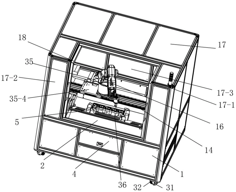
图1为本实施例1中一种自动去毛刺设备一个方向上在滑轨推拉门前端去除一块钢板时的结构立体图;Fig. 1 is the structural perspective view of a kind of automatic deburring equipment in this
图2为本实施例1中同侧两块滑轨推拉拼接时的结构示意图;2 is a schematic structural diagram of two slide rails on the same side during push-pull splicing in the
图3为本实施例1中一种自动去毛刺设备另一个方向上在滑轨推拉门前端去除一块钢板以及第一门板时的结构立体图;3 is a structural perspective view of an automatic deburring device in the other direction of the
图4为图3中A处局部放大图;Fig. 4 is a partial enlarged view at A in Fig. 3;
图5为本实施例1中一种自动去毛刺设备在上方去除C型安全围栏以及第一门板时一个方向的结构立体图;5 is a structural perspective view of one direction when an automatic deburring device in the
图6为本实施例1中一种自动去毛刺设备在上方去除C型安全围栏时一个方向的结构立体图;6 is a structural perspective view in one direction when an automatic deburring device removes a C-type safety fence from above in the
图7为图6中B处局部放大图;Fig. 7 is a partial enlarged view at B in Fig. 6;
图8是六轴去毛刺机器人与驱动机构的结构示意图;Figure 8 is a schematic structural diagram of a six-axis deburring robot and a drive mechanism;
图9为本实施例1中一种自动去毛刺设备在上方去除C型安全围栏以及四块滑轨推拉门时从上往下看时的结构立体图;Fig. 9 is the structural perspective view when looking from top to bottom when an automatic deburring device in the
图10为图9中C处局部放大图。FIG. 10 is a partial enlarged view of C in FIG. 9 .
图中:机架1、废料回收漏斗2、出料口3、废料回收抽屉4、产品工装夹具5、第一安装支架6、第一转轴7、第一连接板8、第二连接板9、第二导轨10、通孔结构11、产品夹具头12、第一电机13、第一导轨14、第一滑块15、六轴去毛刺机器人16、C型安全围栏17、滑轨推拉门18、钢条17-1、钢板17-2、上横板19、第三连接板20、纵板21、第四连接板22、第三滑块23、第四滑块24、推动板25、第一气缸26、第一门板18-1、第二门板18-2、固定座27、压块28、硅胶压头29、导向杆30、安放脚31、滑动滚轮32、限位板33、观察窗34、驱动机构35、第二电机35-1、直线齿条35-2、齿轮35-3、固定连接架35-4、产品36。In the figure:
具体实施方式:Detailed ways:
下面将结合本发明实施例中的附图,对本发明实施例中的技术方案进行清楚、完整地描述,显然,所描述的实施例仅仅是本发明一部分实施例,而不是全部的实施例。基于本发明中的实施例,本领域普通技术人员在没有做出创造性劳动前提下所获得的所有其他实施例,都属于本发明保护的范围。The technical solutions in the embodiments of the present invention will be clearly and completely described below with reference to the accompanying drawings in the embodiments of the present invention. Obviously, the described embodiments are only a part of the embodiments of the present invention, but not all of the embodiments. Based on the embodiments of the present invention, all other embodiments obtained by those of ordinary skill in the art without creative efforts shall fall within the protection scope of the present invention.
请参阅如下实施例,对本发明进行进一步说明:Please refer to the following examples, the present invention is further described:
实施例1:Example 1:
如图1-图10所示,本实施例提供的一种自动去毛刺设备,包括机架1,在机架1上设有底部向下倾斜的废料回收漏斗2,所述废料回收漏斗2的底板倾斜设置,在废料回收漏斗2的底板的低端设有出料口3,在机架1上设有抽拉状的废料回收抽屉4,所述废料回收抽屉4的上方与出料口3贯通,在废料回收漏斗2的上方设有产品工装夹具5,所述产品工装夹具5包括固定在机架1上的两块C型结构的第一安装支架6,且所述两块第一安装支架6分别位于废料回收漏斗2的两侧,在每一块第一安装支架6之间通过第一转轴7转动连接有第一连接板8,两块第一连接板8之间固定有位于废料回收漏斗2上方的第二连接板9,所述第二连接板9的中心为通孔结构11,在第二连接板9上方的四周设有产品夹具头12,在其中一个第一转轴7上连接有驱动该第一转轴7转动的第一电机13,在机架1上连接有位于废料回收漏斗2的后端的第一导轨14,在第一导轨14上滑动连接有第一滑块15,在机架1上设有驱动第一滑块15在第一导轨14内移动的驱动机构35,所述第一滑块15上固定有能够在第一导轨14上水平滑动的六轴去毛刺机器人16,在机架1上设有将机架1上的产品全部围起来的C型安全围栏17,所述C型安全围栏17的缺口17-3上滑动连接有能够滑动到C型安全围栏17内的四扇滑轨推拉门18,四扇滑轨推拉门18两两对开设置且侧边一扇门能够隐藏到另一扇门内的结构,且四扇滑轨推拉门18全部关闭时能够与C型安全围栏17组合构成一个封闭的结构。As shown in FIG. 1-FIG. 10, an automatic deburring device provided in this embodiment includes a
在本实施例中所述的C型安全围栏17通过多根钢条17-1以及钢板17-2拼接而成。The C-shaped
在本实施例中所述的驱动机构35包括位于第一滑块15侧边的第二电机35-1,在第二电机35-1的输出轴上连接有齿轮35-3,在第一滑块15的侧边固定有直线齿条35-2,所述齿轮35-3与直线齿条35-2啮合,所述第二电机35-1通过固定连接架35-4与第一滑块15连接,工作时,当第二电机35-1工作时,带动齿轮35-3旋转,此时齿轮35-3能够在直线齿条35-2内水平移动,最终带动固定连接架35-4也同步移动,在固定连接架35-4移动的过程中带动第一滑块15在第一导轨14上水平移动,最终调整六轴去毛刺机器人16的水平移动过程,来确保六轴去毛刺机器人16能够对不同长度的产品进行去毛刺的加工过程,因此通过上述齿轮齿条传动可以进行左右移动,该设计能够极大的增大工业机器人的活动作业半径。对大工件的加工变成可能,同时也解决了工件两个侧面的去毛刺难度。The
进一步,为了实现自动化操作,在C型安全围栏17的缺口17-3上方以及下方的内侧均设有一条第二导轨10,所述滑轨推拉门18的上横板19的下方设有第三连接板20,所述滑轨推拉门18的纵板21的下方设有第四连接板22,在第三连接板20上方设有与上方的第二导轨10滑动连接的第三滑块23,在第四连接板22上方设有与下方的第二导轨10滑动连接的第四滑块24,且两块第三连接板20位于C型安全围栏17的缺口17-3左侧,另外两块第三连接板20位于C型安全围栏17的缺口17-3右侧,在左侧和右侧的一块第三连接板20上均固定有推动板25,且两块推动板25位于左侧和右侧靠近缺口17-3中心的第三连接板20上,每一块推动板25上设有驱动推动板25往两边移动的第一气缸26。Further, in order to realize automatic operation, a
在本实施例中所述四扇滑轨推拉门18两两对开设置的具体结构如下:在左侧和右侧均设有两块能够拉开后拼接在一起(如图2所示),重叠后变成一块门板的第一门板18-1和第二门板18-2,且左侧的第一门板18-1与右侧的第一门板18-1对开设置,且左侧的第二门板18-2与右侧的第二门板18-2对开设置,同时两块第一门板18-1上的第三连接板20上固定有推动板25,同时两块第一门板18-1对开时能够与第二门板18-2上下重叠后变成一扇门的形式(如图7所示),四扇滑轨推拉门18全部关闭时,能够将C型安全围栏17的缺口17-3封住。通过上述结构设计,实现现有对开门设计对空间利用率不高的问题,最终可以实现自动化开关门。In this embodiment, the specific structure of the four sliding
进一步,为了方便对不同产品的压合作用,所述产品夹具头12包括固定在第二连接板9上的固定座27,在固定座27上通过螺丝连接有压块28,所述压块28的下方设有硅胶压头29,在第二连接板9的通孔结构11侧边设有导向杆30,操作时,利用导向杆30起到导向作用,将产品放在通孔结构11上方,并利用旋转压块28上的螺丝,将四周的压块28分别将产品的四周压紧,实现对产品的固定作用。Further, in order to facilitate the pressing effect on different products, the product fixture head 12 includes a fixing
进一步,方便移动,在机架1的底部四周设有安放脚31,在安放脚31的侧边转动连接有滑动滚轮32。Further, to facilitate movement, there are mounting
为了方便限位,在第一导轨14的两侧设有限位板33,通过设置限位板33避免第一滑块15往两侧移动。In order to facilitate the position limit,
为了方便观察,在每一扇滑轨推拉门18上设有观察窗34,通过设置观察窗34方便查看内部情况。In order to facilitate observation, an
工作时,先将需要去毛刺的产品36安装到产品工装夹具5上,然后驱动六轴去毛刺机器人16工作,利用驱动机构35工作调整六轴去毛刺机器人16左右移动的位置,最终对产品的两侧进行去毛刺的加工过程,同时通过驱动第一电机13工作,带动第二连接板9能够在废料回收漏斗2上方旋转,最终将产品的底部转到到上方,方便六轴去毛刺机器人16对产品的底部进行去毛刺加工,另外加工产生的废料直接通过出料口3进入到废料回收抽屉4内,后期通过抽拉废料回收抽屉4即可,将废料进行方便快速的收集,因此通过上述结构设计能够实现对工件的底部(夹具下面镂空设计)正面下边缘、侧边进行去毛刺作业,从而实现该设备能够对需要作业的空间进行无死角去毛刺,实现真正意义的自动化,另外上方设置于C型安全围栏17,以及自动化对开门设计,避免加工过程中废料乱飞的问题,因此本发明具有以下优点:1、加工过程中毛刺不会乱飞,导致后期清理方便,使用更安全;2、实现自动化翻转产品,提高工作效率,去毛刺效果更好;3、对加工大零件也相对方便;4、废料回收更方便、快捷。When working, first install the
对于本领域技术人员而言,显然本发明不限于上述示范性实施例的细节,而且在不背离本发明的精神或基本特征的情况下,能够以其他的具体形式实现本发明。因此,无论从哪一点来看,均应将实施例看作是示范性的,而且是非限制性的,本发明的范围由所附权利要求而不是上述说明限定,因此旨在将落在权利要求的等同要件的含义和范围内的所有变化囊括在本发明内。不应将权利要求中的任何附图标记视为限制所涉及的权利要求。It will be apparent to those skilled in the art that the present invention is not limited to the details of the above-described exemplary embodiments, but that the present invention may be embodied in other specific forms without departing from the spirit or essential characteristics of the invention. Therefore, the embodiments are to be regarded in all respects as illustrative and not restrictive, and the scope of the invention is to be defined by the appended claims rather than the foregoing description, which are therefore intended to fall within the scope of the claims. All changes within the meaning and scope of the equivalents of , are included in the present invention. Any reference signs in the claims shall not be construed as limiting the involved claim.
Claims (6)
Priority Applications (1)
| Application Number | Priority Date | Filing Date | Title |
|---|---|---|---|
| CN201911167297.XA CN110802465B (en) | 2019-11-25 | 2019-11-25 | Automatic deburring equipment |
Applications Claiming Priority (1)
| Application Number | Priority Date | Filing Date | Title |
|---|---|---|---|
| CN201911167297.XA CN110802465B (en) | 2019-11-25 | 2019-11-25 | Automatic deburring equipment |
Publications (2)
| Publication Number | Publication Date |
|---|---|
| CN110802465A true CN110802465A (en) | 2020-02-18 |
| CN110802465B CN110802465B (en) | 2025-05-30 |
Family
ID=69491365
Family Applications (1)
| Application Number | Title | Priority Date | Filing Date |
|---|---|---|---|
| CN201911167297.XA Active CN110802465B (en) | 2019-11-25 | 2019-11-25 | Automatic deburring equipment |
Country Status (1)
| Country | Link |
|---|---|
| CN (1) | CN110802465B (en) |
Cited By (2)
| Publication number | Priority date | Publication date | Assignee | Title |
|---|---|---|---|---|
| WO2024023463A1 (en) | 2022-07-29 | 2024-02-01 | Comau France | Machine tool |
| CN117772707A (en) * | 2023-12-26 | 2024-03-29 | 重庆川仪自动化股份有限公司 | Cleaning device for blind holes in workpieces |
Citations (6)
| Publication number | Priority date | Publication date | Assignee | Title |
|---|---|---|---|---|
| JP2000000741A (en) * | 1998-06-15 | 2000-01-07 | Sanyo Machine Kk | Six-surface continuous automatic finishing machine and machining method using the finishing machine |
| WO2006046581A1 (en) * | 2004-10-29 | 2006-05-04 | Jtekt Corporation | Grinding machine |
| CN105127856A (en) * | 2015-08-06 | 2015-12-09 | 宁波亚路机械有限公司 | Automatic grinding machine |
| CN205685147U (en) * | 2016-05-18 | 2016-11-16 | 东莞市誉山自动化科技有限公司 | A full-automatic plastic mobile phone case full grinding equipment |
| CN110315403A (en) * | 2019-07-24 | 2019-10-11 | 上海普莱克斯自动设备制造有限公司 | The Workholding Approaches of robotic deburring's polishing work station and the application work station |
| CN211465786U (en) * | 2019-11-25 | 2020-09-11 | 铜车马动力科技(宁波)有限公司 | Automatic deburring equipment |
-
2019
- 2019-11-25 CN CN201911167297.XA patent/CN110802465B/en active Active
Patent Citations (6)
| Publication number | Priority date | Publication date | Assignee | Title |
|---|---|---|---|---|
| JP2000000741A (en) * | 1998-06-15 | 2000-01-07 | Sanyo Machine Kk | Six-surface continuous automatic finishing machine and machining method using the finishing machine |
| WO2006046581A1 (en) * | 2004-10-29 | 2006-05-04 | Jtekt Corporation | Grinding machine |
| CN105127856A (en) * | 2015-08-06 | 2015-12-09 | 宁波亚路机械有限公司 | Automatic grinding machine |
| CN205685147U (en) * | 2016-05-18 | 2016-11-16 | 东莞市誉山自动化科技有限公司 | A full-automatic plastic mobile phone case full grinding equipment |
| CN110315403A (en) * | 2019-07-24 | 2019-10-11 | 上海普莱克斯自动设备制造有限公司 | The Workholding Approaches of robotic deburring's polishing work station and the application work station |
| CN211465786U (en) * | 2019-11-25 | 2020-09-11 | 铜车马动力科技(宁波)有限公司 | Automatic deburring equipment |
Cited By (3)
| Publication number | Priority date | Publication date | Assignee | Title |
|---|---|---|---|---|
| WO2024023463A1 (en) | 2022-07-29 | 2024-02-01 | Comau France | Machine tool |
| FR3138337A1 (en) * | 2022-07-29 | 2024-02-02 | Comau France | MACHINE TOOL |
| CN117772707A (en) * | 2023-12-26 | 2024-03-29 | 重庆川仪自动化股份有限公司 | Cleaning device for blind holes in workpieces |
Also Published As
| Publication number | Publication date |
|---|---|
| CN110802465B (en) | 2025-05-30 |
Similar Documents
| Publication | Publication Date | Title |
|---|---|---|
| CN206230619U (en) | A kind of plank punch-cuts all-in-one | |
| CN110802465A (en) | An automatic deburring device | |
| CN211465786U (en) | Automatic deburring equipment | |
| CN118237968B (en) | A machine tool workbench with waste collection function | |
| CN215615862U (en) | A laser cutting machine for transformer shock absorber processing capable of precise positioning and cutting | |
| CN220312203U (en) | Welding equipment for aluminum profile machining | |
| CN216461847U (en) | Automatic high-efficient drilling equipment of machine-building | |
| CN215433202U (en) | Fixing clamp for processing plastic steel glass door and window | |
| CN214162545U (en) | Burnishing device is used in aluminum alloy door and window processing convenient to it is fixed | |
| CN211991012U (en) | A punching device for easy adjustment of drilling position | |
| CN116372463A (en) | Welding device for computer panel production | |
| CN115347479A (en) | Electrical control cabinet safe in utilization | |
| CN211438953U (en) | Gantry machining equipment with chip removal function | |
| CN217965510U (en) | Automatic welding equipment for door grating | |
| CN115343518A (en) | Capacitor voltage transformer | |
| CN221966957U (en) | Automatic tapping device for door and window lock | |
| CN209632127U (en) | A ball mill with automatic screening function for metal powder production | |
| CN213136124U (en) | Deburring device for plate processing | |
| CN219504277U (en) | A vertical machining center | |
| CN222134413U (en) | Robot removes ground rail slip table for steel sheet is polished | |
| CN209836231U (en) | Special laser head moving device for gear laser quenching machine | |
| CN220560276U (en) | Precision part processing stamping equipment | |
| CN221336791U (en) | Clamping and adjusting device for plate shearing machine | |
| CN220296421U (en) | Clamp for machining stainless steel castings | |
| CN221716367U (en) | A protective door for CNC machine tools |
Legal Events
| Date | Code | Title | Description |
|---|---|---|---|
| PB01 | Publication | ||
| PB01 | Publication | ||
| SE01 | Entry into force of request for substantive examination | ||
| GR01 | Patent grant | ||
| GR01 | Patent grant |