CN110856444A - Sliding device provided with an improved locking device for a vehicle seat - Google Patents
Sliding device provided with an improved locking device for a vehicle seat Download PDFInfo
- Publication number
- CN110856444A CN110856444A CN201980002638.XA CN201980002638A CN110856444A CN 110856444 A CN110856444 A CN 110856444A CN 201980002638 A CN201980002638 A CN 201980002638A CN 110856444 A CN110856444 A CN 110856444A
- Authority
- CN
- China
- Prior art keywords
- locking
- rail
- rails
- sliding device
- locking pin
- Prior art date
- Legal status (The legal status is an assumption and is not a legal conclusion. Google has not performed a legal analysis and makes no representation as to the accuracy of the status listed.)
- Granted
Links
Images


Classifications
-
- B—PERFORMING OPERATIONS; TRANSPORTING
- B60—VEHICLES IN GENERAL
- B60N—SEATS SPECIALLY ADAPTED FOR VEHICLES; VEHICLE PASSENGER ACCOMMODATION NOT OTHERWISE PROVIDED FOR
- B60N2/00—Seats specially adapted for vehicles; Arrangement or mounting of seats in vehicles
- B60N2/02—Seats specially adapted for vehicles; Arrangement or mounting of seats in vehicles the seat or part thereof being movable, e.g. adjustable
- B60N2/04—Seats specially adapted for vehicles; Arrangement or mounting of seats in vehicles the seat or part thereof being movable, e.g. adjustable the whole seat being movable
- B60N2/06—Seats specially adapted for vehicles; Arrangement or mounting of seats in vehicles the seat or part thereof being movable, e.g. adjustable the whole seat being movable slidable
- B60N2/08—Seats specially adapted for vehicles; Arrangement or mounting of seats in vehicles the seat or part thereof being movable, e.g. adjustable the whole seat being movable slidable characterised by the locking device
- B60N2/0831—Movement of the latch
- B60N2/0862—Movement of the latch sliding
- B60N2/0875—Movement of the latch sliding in a vertical direction
-
- B—PERFORMING OPERATIONS; TRANSPORTING
- B60—VEHICLES IN GENERAL
- B60N—SEATS SPECIALLY ADAPTED FOR VEHICLES; VEHICLE PASSENGER ACCOMMODATION NOT OTHERWISE PROVIDED FOR
- B60N2/00—Seats specially adapted for vehicles; Arrangement or mounting of seats in vehicles
- B60N2/02—Seats specially adapted for vehicles; Arrangement or mounting of seats in vehicles the seat or part thereof being movable, e.g. adjustable
- B60N2/04—Seats specially adapted for vehicles; Arrangement or mounting of seats in vehicles the seat or part thereof being movable, e.g. adjustable the whole seat being movable
- B60N2/06—Seats specially adapted for vehicles; Arrangement or mounting of seats in vehicles the seat or part thereof being movable, e.g. adjustable the whole seat being movable slidable
- B60N2/07—Slide construction
- B60N2/0702—Slide construction characterised by its cross-section
- B60N2/0715—C or U-shaped
-
- B—PERFORMING OPERATIONS; TRANSPORTING
- B60—VEHICLES IN GENERAL
- B60N—SEATS SPECIALLY ADAPTED FOR VEHICLES; VEHICLE PASSENGER ACCOMMODATION NOT OTHERWISE PROVIDED FOR
- B60N2/00—Seats specially adapted for vehicles; Arrangement or mounting of seats in vehicles
- B60N2/02—Seats specially adapted for vehicles; Arrangement or mounting of seats in vehicles the seat or part thereof being movable, e.g. adjustable
- B60N2/04—Seats specially adapted for vehicles; Arrangement or mounting of seats in vehicles the seat or part thereof being movable, e.g. adjustable the whole seat being movable
- B60N2/06—Seats specially adapted for vehicles; Arrangement or mounting of seats in vehicles the seat or part thereof being movable, e.g. adjustable the whole seat being movable slidable
- B60N2/07—Slide construction
- B60N2/0722—Constructive details
- B60N2/0727—Stop members for limiting sliding movement
-
- B—PERFORMING OPERATIONS; TRANSPORTING
- B60—VEHICLES IN GENERAL
- B60N—SEATS SPECIALLY ADAPTED FOR VEHICLES; VEHICLE PASSENGER ACCOMMODATION NOT OTHERWISE PROVIDED FOR
- B60N2/00—Seats specially adapted for vehicles; Arrangement or mounting of seats in vehicles
- B60N2/02—Seats specially adapted for vehicles; Arrangement or mounting of seats in vehicles the seat or part thereof being movable, e.g. adjustable
- B60N2/04—Seats specially adapted for vehicles; Arrangement or mounting of seats in vehicles the seat or part thereof being movable, e.g. adjustable the whole seat being movable
- B60N2/06—Seats specially adapted for vehicles; Arrangement or mounting of seats in vehicles the seat or part thereof being movable, e.g. adjustable the whole seat being movable slidable
- B60N2/08—Seats specially adapted for vehicles; Arrangement or mounting of seats in vehicles the seat or part thereof being movable, e.g. adjustable the whole seat being movable slidable characterised by the locking device
-
- B—PERFORMING OPERATIONS; TRANSPORTING
- B60—VEHICLES IN GENERAL
- B60N—SEATS SPECIALLY ADAPTED FOR VEHICLES; VEHICLE PASSENGER ACCOMMODATION NOT OTHERWISE PROVIDED FOR
- B60N2/00—Seats specially adapted for vehicles; Arrangement or mounting of seats in vehicles
- B60N2/02—Seats specially adapted for vehicles; Arrangement or mounting of seats in vehicles the seat or part thereof being movable, e.g. adjustable
- B60N2/04—Seats specially adapted for vehicles; Arrangement or mounting of seats in vehicles the seat or part thereof being movable, e.g. adjustable the whole seat being movable
- B60N2/06—Seats specially adapted for vehicles; Arrangement or mounting of seats in vehicles the seat or part thereof being movable, e.g. adjustable the whole seat being movable slidable
- B60N2/08—Seats specially adapted for vehicles; Arrangement or mounting of seats in vehicles the seat or part thereof being movable, e.g. adjustable the whole seat being movable slidable characterised by the locking device
- B60N2/0806—Seats specially adapted for vehicles; Arrangement or mounting of seats in vehicles the seat or part thereof being movable, e.g. adjustable the whole seat being movable slidable characterised by the locking device with pin alignment systems, e.g. with at least one of a plurality of locking pins always aligned w.r.t. at least one of a plurality of pin-receiving elements
-
- B—PERFORMING OPERATIONS; TRANSPORTING
- B60—VEHICLES IN GENERAL
- B60N—SEATS SPECIALLY ADAPTED FOR VEHICLES; VEHICLE PASSENGER ACCOMMODATION NOT OTHERWISE PROVIDED FOR
- B60N2/00—Seats specially adapted for vehicles; Arrangement or mounting of seats in vehicles
- B60N2/02—Seats specially adapted for vehicles; Arrangement or mounting of seats in vehicles the seat or part thereof being movable, e.g. adjustable
- B60N2/04—Seats specially adapted for vehicles; Arrangement or mounting of seats in vehicles the seat or part thereof being movable, e.g. adjustable the whole seat being movable
- B60N2/06—Seats specially adapted for vehicles; Arrangement or mounting of seats in vehicles the seat or part thereof being movable, e.g. adjustable the whole seat being movable slidable
- B60N2/08—Seats specially adapted for vehicles; Arrangement or mounting of seats in vehicles the seat or part thereof being movable, e.g. adjustable the whole seat being movable slidable characterised by the locking device
- B60N2/0812—Location of the latch
- B60N2/0818—Location of the latch inside the rail
-
- B—PERFORMING OPERATIONS; TRANSPORTING
- B60—VEHICLES IN GENERAL
- B60N—SEATS SPECIALLY ADAPTED FOR VEHICLES; VEHICLE PASSENGER ACCOMMODATION NOT OTHERWISE PROVIDED FOR
- B60N2/00—Seats specially adapted for vehicles; Arrangement or mounting of seats in vehicles
- B60N2/02—Seats specially adapted for vehicles; Arrangement or mounting of seats in vehicles the seat or part thereof being movable, e.g. adjustable
- B60N2/04—Seats specially adapted for vehicles; Arrangement or mounting of seats in vehicles the seat or part thereof being movable, e.g. adjustable the whole seat being movable
- B60N2/06—Seats specially adapted for vehicles; Arrangement or mounting of seats in vehicles the seat or part thereof being movable, e.g. adjustable the whole seat being movable slidable
- B60N2/08—Seats specially adapted for vehicles; Arrangement or mounting of seats in vehicles the seat or part thereof being movable, e.g. adjustable the whole seat being movable slidable characterised by the locking device
- B60N2/0881—Activation of the latches by the control mechanism
-
- B—PERFORMING OPERATIONS; TRANSPORTING
- B60—VEHICLES IN GENERAL
- B60N—SEATS SPECIALLY ADAPTED FOR VEHICLES; VEHICLE PASSENGER ACCOMMODATION NOT OTHERWISE PROVIDED FOR
- B60N2/00—Seats specially adapted for vehicles; Arrangement or mounting of seats in vehicles
- B60N2/02—Seats specially adapted for vehicles; Arrangement or mounting of seats in vehicles the seat or part thereof being movable, e.g. adjustable
- B60N2/04—Seats specially adapted for vehicles; Arrangement or mounting of seats in vehicles the seat or part thereof being movable, e.g. adjustable the whole seat being movable
- B60N2/06—Seats specially adapted for vehicles; Arrangement or mounting of seats in vehicles the seat or part thereof being movable, e.g. adjustable the whole seat being movable slidable
- B60N2/08—Seats specially adapted for vehicles; Arrangement or mounting of seats in vehicles the seat or part thereof being movable, e.g. adjustable the whole seat being movable slidable characterised by the locking device
- B60N2/0881—Activation of the latches by the control mechanism
- B60N2/0887—Activation of the latches by the control mechanism with synchronised movements
Landscapes
- Engineering & Computer Science (AREA)
- Aviation & Aerospace Engineering (AREA)
- Transportation (AREA)
- Mechanical Engineering (AREA)
- Seats For Vehicles (AREA)
Abstract
Description
技术领域technical field
本发明涉及用于车辆座椅的设置有改进的锁定装置的滑动装置。The present invention relates to a sliding device provided with an improved locking device for a vehicle seat.
更具体地,本发明涉及用于车辆座椅的设置有锁定装置的滑动装置,该锁定装置具有紧凑的结构和改进的可靠性。More particularly, the present invention relates to a sliding device for a vehicle seat provided with a locking device having a compact structure and improved reliability.
背景技术Background technique
车辆座椅通常具有用于在向前或向后方向上推动或拉动座椅坐垫的滑动功能、用于调节座椅坐垫的高度的高度调节功能以及用于调节座椅靠背相对于座椅坐垫的倾斜度的斜倚功能。Vehicle seats typically have a sliding function for pushing or pulling the seat cushion in a forward or rearward direction, a height adjustment function for adjusting the height of the seat cushion, and a tilting function for adjusting the seat back relative to the seat cushion degree of reclining function.
上述的滑动功能通常由滑动装置来实现,该滑动装置包括一对平行的轨道,所述一对平行的轨道中的每一个轨道包括附接至车辆地板的下导轨和附接至车辆座椅的上导轨,上导轨被约束至下导轨,但是上导轨能够相对于所述下导轨滑动。The sliding function described above is typically accomplished by a sliding device comprising a pair of parallel rails, each rail of the pair of parallel rails comprising a lower rail attached to the vehicle floor and a rail attached to the vehicle seat. The upper rail, which is constrained to the lower rail, but which is capable of sliding relative to said lower rail.
滑动装置还包括用于允许/防止上导轨相对于下导轨的运动的锁定装置。这种锁定装置通常处于锁定构型,在该锁定构型中,这种锁定装置防止上导轨相对于下导轨滑动,从而避免座椅相对于车辆地板的意外的移位。The sliding device also includes locking means for allowing/preventing movement of the upper rail relative to the lower rail. Such locking devices are normally in a locked configuration in which they prevent the upper rail from sliding relative to the lower rail, thereby avoiding accidental displacement of the seat relative to the vehicle floor.
这种锁定装置通常包括一对锁定组件,针对每个轨道设置一个锁定组件。Such locking devices typically include a pair of locking assemblies, one for each track.
滑动装置还设置有释放构件,该释放构件可以由使用者使用,以用于将锁定装置的锁定组件移动至解锁构型,在该解锁构型中,上导轨相对于下导轨自由移动,使得座椅相对于车辆地板的位置可以被调节。这种释放构件可以例如制成为具有两个大致平行的臂的“U”形把手或者毛巾杆(towel bar),该“U”形把手或者毛巾杆的端部部分构造成同时作用在相应的锁定组件上,以用于将相应的锁定组件驱动至其解锁构型。The sliding device is also provided with a release member that can be used by a user for moving the locking assembly of the locking device to an unlocked configuration in which the upper rail is free to move relative to the lower rail such that the seat The position of the seat relative to the vehicle floor can be adjusted. Such a release member may for example be made as a "U" shaped handle or towel bar with two substantially parallel arms, the end portions of which are configured to simultaneously act on the respective locking assembly for driving the corresponding locking assembly to its unlocked configuration.
从现有技术已知滑动装置,其中,为了在上导轨与下导轨之间提供形状配合接合,每个轨道的下导轨设置有一系列孔口,所述一系列孔口沿着所述下导轨的纵向轴线对齐并且优选地彼此等距地间隔开,并且每个锁定组件连接至相应的上导轨,并且每个锁定组件包括一个或更多个锁定销,所述一个或更多个锁定销构造成穿入下导轨的相应的孔口中并且与所述孔口的边缘接合。Slide devices are known from the prior art in which, in order to provide a form-fit engagement between the upper and lower rails, the lower rail of each rail is provided with a series of apertures along the length of the lower rail. The longitudinal axes are aligned and preferably equally spaced from each other, and each locking assembly is connected to a corresponding upper rail, and each locking assembly includes one or more locking pins configured to Pass into the corresponding aperture of the lower rail and engage the edge of the aperture.
优选地,设置了若干锁定销,并且所述锁定销的尺寸、所述锁定销之间的距离、下导轨中的孔口的尺寸以及所述孔口之间的距离选择成使得至少一个锁定销总是与对应的孔口对准,使得至少一个锁定销可以穿入所述孔口中并且接合所述孔口的边缘。Preferably, several locking pins are provided and the dimensions of the locking pins, the distance between the locking pins, the dimensions of the apertures in the lower rail and the distance between the apertures are selected such that at least one locking pin Always align with the corresponding aperture so that at least one locking pin can penetrate into the aperture and engage the edge of the aperture.
最优选地,所述锁定销的尺寸、所述锁定销之间的距离、下导轨中的孔口的尺寸以及所述孔口之间的距离被选择成使得,至少第一锁定销定位成使得穿入对应的孔口中并且与对应的孔口的边缘的前侧部接合,并且至少第二锁定销定位成使得穿入对应的孔口中并且与对应的孔口的边缘的后侧部接合,从而获得“无夹紧式(chuckless)”接合。Most preferably, the dimensions of the locking pins, the distance between the locking pins, the dimensions of the apertures in the lower rail and the distance between the apertures are selected such that at least the first locking pin is positioned such that Passing into the corresponding aperture and engaging the front side of the edge of the corresponding aperture, and at least a second locking pin is positioned so as to pass into the corresponding aperture and engage the rear side of the edge of the corresponding aperture, thereby A "chuckless" joint is obtained.
这种锁定销通常例如借助于弹簧偏置至锁定构型,在该锁定构型中,锁定销中的至少一些锁定销接合下导轨的相应的孔口。Such locking pins are typically biased, eg by means of springs, to a locked configuration in which at least some of the locking pins engage corresponding apertures of the lower rail.
为了将锁定组件移动至锁定组件的解锁构型,以用于调节车辆座椅相对于车辆地板的位置,设置有释放构件,比如释放毛巾杆或者把手,该释放构件作用在相应的连接构件上,针对每个锁定组件设置一个连接构件:所述连接构件继而作用在相应的锁定组件的锁定销上,以将相应的锁定组件的锁定销移动至解锁构型,在该解锁构型中,相应的锁定组件的锁定销与相应的下导轨的孔口断开接合。In order to move the locking assembly to the unlocked configuration of the locking assembly for adjusting the position of the vehicle seat relative to the vehicle floor, a release member, such as a release towel bar or handle, is provided which acts on the corresponding connecting member, One connecting member is provided for each locking assembly: said connecting member in turn acts on the locking pin of the corresponding locking assembly to move the locking pin of the corresponding locking assembly into an unlocked configuration in which the corresponding The locking pins of the locking assemblies are disengaged from the corresponding apertures of the lower rail.
为此目的,锁定销通常设置有扩大的头部,并且连接构件设置有叉形元件,该叉形元件适于接合销头部以用于将所述销从下导轨的孔口取出。For this purpose, the locking pin is usually provided with an enlarged head and the connecting member is provided with a fork-shaped element adapted to engage the pin head for extracting said pin from the aperture of the lower rail.
例如在文献US 2003/006355、US 7980525以及US 6637712中公开了用于车辆座椅的滑动装置的这种锁定装置。Such locking devices for sliding devices of vehicle seats are disclosed, for example, in documents US 2003/006355, US 7980525 and US 6637712.
然而,上述文献中所公开的这种锁定装置并非没有缺点。However, the locking device disclosed in the above-mentioned document is not without drawbacks.
更特别地,在已知的锁定装置中,将释放构件连接至锁定组件的连接构件部分地或完全地布置在滑动装置的轨道的外部。More particularly, in the known locking device, the connecting member connecting the release member to the locking assembly is arranged partially or completely outside the track of the sliding device.
这带来下述需要:在设计滑动装置时提供足够的空间以用于接纳所述连接构件。This brings about the need to provide sufficient space for receiving the connecting member when designing the sliding device.
此外,由于这些连接构件至少部分地布置在滑动装置的轨道的外部,因此这些连接构件暴露于灰尘和污垢,所述灰尘和污垢可能积聚在这些连接构件的移动部分之间,并且使得这些连接构件的移动部分发生故障。Furthermore, since the connecting members are arranged at least partially outside the rails of the sliding device, the connecting members are exposed to dust and dirt, which may accumulate between the moving parts of the connecting members and cause the connecting members to The moving part of the device fails.
这种灰尘和污垢也可能渗透至滑动装置的轨道中,并且干扰锁定销从锁定销的锁定构型向锁定销的解锁构型的运动,以及干扰锁定销从锁定销的解锁构型向锁定销的锁定构型的运动。常见的故障问题包括增加释放力、增加滑动力以及噪音问题,这可能会引起使用者的不满。Such dust and dirt may also penetrate into the track of the slide and interfere with the movement of the locking pin from the locked configuration of the locking pin to the unlocked configuration of the locking pin, and from the unlocked configuration of the locking pin to the locking pin movement in the locked configuration. Common failure issues include increased release force, increased sliding force, and noise issues, which can lead to user dissatisfaction.
因此,本发明的主要目的是提供用于车辆座椅的设置有改进的锁定装置的滑动装置,该改进的锁定装置具有紧凑的结构。Therefore, the main object of the present invention is to provide a sliding device for a vehicle seat provided with an improved locking device having a compact structure.
本发明的另一目的是提供用于车辆座椅的设置有改进的锁定装置的滑动装置,该改进的锁定装置具有改进的可靠性,即避免了由于污垢和尘土在所述锁定装置的运动部件附近的积聚而引起故障的风险。Another object of the present invention is to provide a sliding device for a vehicle seat provided with an improved locking device with improved reliability, ie avoiding dirt and dust on the moving parts of the locking device Risk of malfunction due to nearby build-up.
通过所附权利要求中所要求保护的滑动装置来实现这些目的和其他目的。These and other objects are achieved by a sliding device as claimed in the appended claims.
发明内容SUMMARY OF THE INVENTION
本发明涉及用于车辆座椅的滑动装置,该滑动装置包括一对平行的轨道,所述一对平行的轨道各自包括用于附接至车辆地板的下导轨和用于附接至车辆座椅并且以可滑动的方式安装至所述下导轨的上导轨,每个下导轨包括多个孔口,所述多个孔口沿着所述下导轨的纵向轴线对齐并且彼此等距地间隔开。The present invention relates to a sliding device for a vehicle seat, the sliding device comprising a pair of parallel rails each comprising a lower rail for attachment to the vehicle floor and for attachment to the vehicle seat and slidably mounted to the upper rails of the lower rails, each lower rail including a plurality of apertures aligned along the longitudinal axis of the lower rail and equally spaced from each other.
滑动装置还包括锁定装置,该锁定装置包括与每个轨道相关联的锁定组件,以用于选择性地允许/防止所述上导轨相对于所述下导轨的运动。每个锁定组件连接至相应的上导轨,并且每个锁定组件包括一个或更多个锁定销,所述一个或更多个锁定销构造成穿入相应的下导轨的对应的孔口中并且接合所述孔口的边缘,所述锁定销例如通过弹簧装置偏置至锁定构型。The slide device also includes a locking device including a locking assembly associated with each rail for selectively allowing/preventing movement of the upper rail relative to the lower rail. Each locking assembly is connected to a corresponding upper rail, and each locking assembly includes one or more locking pins configured to penetrate into corresponding apertures of the corresponding lower rail and engage all The edge of the aperture, the locking pin is biased to the locked configuration, for example by spring means.
根据本发明的优选实施方式,每个锁定组件包括多个锁定销。根据本发明的特别优选的实施方式,这种锁定销定尺寸且布置成使得,对于上导轨相对于下导轨的任何位置,至少一个锁定销与相应的下导轨的对应的孔口对准,并且至少一个锁定销可以穿入所述孔口中并且接合所述孔口的边缘。According to a preferred embodiment of the present invention, each locking assembly includes a plurality of locking pins. According to a particularly preferred embodiment of the invention, such locking pins are dimensioned and arranged such that, for any position of the upper rail relative to the lower rail, at least one locking pin is aligned with the corresponding aperture of the corresponding lower rail, and At least one locking pin can penetrate into the aperture and engage an edge of the aperture.
锁定装置还设置有释放组件,该释放组件用于同时将所述锁定组件从锁定构型切换至解锁构型,在该锁定构型中,防止轨道的上导轨相对于相应的下导轨的运动,在该解锁构型中,允许所述上导轨相对于相应的下导轨的运动。The locking device is also provided with a release assembly for simultaneously switching said locking assembly from a locked configuration to an unlocked configuration in which movement of the upper rail of the track relative to the corresponding lower rail is prevented, In this unlocked configuration, movement of the upper rail relative to the corresponding lower rail is permitted.
所述释放组件包括释放构件和一对连接构件,针对每个锁定组件设置一个连接构件,一方面,所述连接构件中的每一个连接构件与释放构件以力传递的方式连接,另一方面,所述连接构件中的每一个连接构件与相应的锁定组件的锁定销以力传递的方式连接。The release assembly includes a release member and a pair of connection members, one connection member is provided for each locking assembly, on the one hand, each of the connection members is connected with the release member in a force-transmitting manner, and on the other hand, Each of the connecting members is force-transmittingly connected with the locking pin of the corresponding locking assembly.
此外,当使用者对释放构件施加力时,这种力从释放构件传递至连接构件,并且从所述连接构件传递至相应的锁定组件的锁定销,从而将所述锁定销从所述锁定销的锁定构型驱动至所述锁定销的解锁构型。Furthermore, when a user applies a force to the release member, this force is transmitted from the release member to the connecting member, and from the connecting member to the locking pin of the corresponding locking assembly, thereby removing the locking pin from the locking pin The locked configuration of is driven to the unlocked configuration of the locking pin.
根据本发明,这种连接构件完全地接纳在相应的轨道的内侧,并且这种连接构件布置在相应的轨道的上导轨与下导轨之间。According to the invention, such connecting members are received completely inside the respective rails and are arranged between the upper and lower rails of the respective rails.
这种布置允许获得紧凑的结构,这使得相对于现有解决方案中提出的外部释放系统在包装滑动装置方面是有利的,其中,释放组件的连接构件至少部分地布置在相应的轨道的外部。This arrangement allows to obtain a compact structure, which makes it advantageous in terms of packaging the slide with respect to external release systems proposed in existing solutions, wherein the connecting members of the release assemblies are arranged at least partially outside the respective rails.
根据本发明的优选实施方式,每个锁定组件包括支承板,该支承板紧固(例如焊接和/或桩接)至相应的上导轨,并且该支承板设置有窗口,锁定销可以滑动穿过该窗口以用于从锁定销的解锁构型移动至锁定销的锁定构型,以及用于从锁定销的锁定构型移动至锁定销的解锁构型。According to a preferred embodiment of the invention, each locking assembly comprises a support plate fastened (eg welded and/or staked) to the corresponding upper rail and provided with windows through which the locking pins can slide The window is for movement from the unlocked configuration of the locking pin to the locked configuration of the locking pin, and from the locked configuration of the locking pin to the unlocked configuration of the locking pin.
每个连接构件对应地制成为弹簧板,该弹簧板包括用于与释放构件接合的接合部分、用于将锁定销从锁定销的锁定构型驱动至锁定销的解锁构型的驱动部分以及用于连接至锁定组件的支承板的连接部分。Each connecting member is correspondingly made as a spring plate comprising an engagement portion for engaging with the release member, a drive portion for driving the locking pin from the locked configuration of the locking pin to the unlocked configuration of the locking pin, and a to the connecting portion of the support plate connected to the locking assembly.
根据该优选实施方式,当使用者对释放构件施加力时,这种力传递至弹簧板并且引起所述弹簧板的旋转,该弹簧板继而将锁定销驱动至锁定销的解锁构型。According to this preferred embodiment, when a user applies a force to the release member, this force is transmitted to and causes rotation of the spring plate, which in turn drives the locking pin to its unlocked configuration.
根据本发明的优选实施方式,锁定销设置有横向突出栓,并且弹簧板的驱动部分包括窗口,该窗口的宽度大于锁定销的直径但小于锁定销的直径与突出栓的长度之和,使得弹簧板的驱动部分的窗口的边缘可以接合这种栓,以用于将锁定销驱动至锁定销的解锁构型。According to a preferred embodiment of the invention, the locking pin is provided with a laterally protruding peg, and the drive portion of the spring plate includes a window, the width of which is greater than the diameter of the locking pin but smaller than the sum of the diameter of the locking pin and the length of the protruding peg, so that the spring The edge of the window of the drive portion of the plate may engage such a peg for driving the locking pin to the unlocked configuration of the locking pin.
根据本发明的优选实施方式,释放构件制成为具有两个大致平行的臂的“U”形把手,并且每个弹簧板的接合部分构造成接纳所述释放把手的相应的臂的端部部分。According to a preferred embodiment of the present invention, the release member is made as a "U" shaped handle with two substantially parallel arms, and the engagement portion of each spring plate is configured to receive the end portion of the respective arm of the release handle.
附图说明Description of drawings
根据参照附图以非限制性示例的方式给出的本发明的优选实施方式的详细描述,本发明的其他特征和优点将会更加明显,在附图中:Other features and advantages of the invention will become more apparent from the detailed description of preferred embodiments of the invention, given by way of non-limiting example with reference to the accompanying drawings, in which:
图1是根据本发明的滑动装置的立体图;1 is a perspective view of a sliding device according to the present invention;
图2是沿着线II-II截取的图1的滑动装置的横截面图;FIG. 2 is a cross-sectional view of the slide device of FIG. 1 taken along line II-II;
图3a是图2的细节III的放大图,其以第一锁定构型示出;Figure 3a is an enlarged view of detail III of Figure 2, shown in the first locked configuration;
图3b是图2的细节III的放大图,其以第二解锁构型示出;Figure 3b is an enlarged view of detail III of Figure 2, shown in a second unlocked configuration;
图4是图2的锁定组件的连接构件的立体图;Figure 4 is a perspective view of a connecting member of the locking assembly of Figure 2;
图5a以横截面图部分地示出了根据本发明的变型的滑动装置的锁定装置;Figure 5a partially shows in cross-section the locking device of the sliding device according to a variant of the invention;
图5b以立体的局部剖视图部分地示出了图5a的锁定装置;Figure 5b partially shows the locking device of Figure 5a in a perspective partial cross-sectional view;
图6a示出了图2的锁定组件的锁定销的第一锁定构型;Figure 6a shows a first locking configuration of the locking pin of the locking assembly of Figure 2;
图6b示出了图2的锁定组件的锁定销的第二锁定构型;Figure 6b shows a second locking configuration of the locking pin of the locking assembly of Figure 2;
图6c示出了图2的锁定组件的锁定销的第三锁定构型。Figure 6c shows a third locking configuration of the locking pin of the locking assembly of Figure 2 .
具体实施方式Detailed ways
参照图1,示出了根据本发明的滑动装置10。Referring to Figure 1, a
以本身已知的方式,滑动装置10包括一对平行的轨道20a、20b,所述一对平行的轨道20a、20b各自包括用于附接至车辆地板的下导轨30a、30b和用于附接至车辆座椅的框架的上导轨40a、40b。In a manner known per se, the
每个上导轨40a、40b被约束至相应的下导轨30a、30b,但是每个上导轨40a、40b可以相对于所述下导轨滑动。Each
为了选择性地允许/防止轨道20a、20b的上导轨相对于下导轨的滑动运动,设置有锁定装置。所述锁定装置包括两个锁定组件,针对每个轨道20a、20b设置一个锁定组件。In order to selectively allow/prevent sliding movement of the upper rails of the
图2至图4中示出了所述锁定组件中的一个锁定组件。目的在于另一锁定组件与图2至图4中所示的锁定组件相同。One of the locking assemblies is shown in FIGS. 2-4 . The intention is that the other locking assembly is the same as the one shown in Figures 2-4.
每个锁定组件1a、1b包括支承板3a、3b和一个或更多个锁定销5a、5b(在所示出的实施方式中为三个),所述支承板3a、3b紧固(例如焊接和/或桩接)至相应的上导轨40a、40b,并且一个或更多个锁定销5a、5b构造成穿过设置在相应的上导轨40a、40b中的孔口42a、42b并且穿过设置在支承板3a、3b中的窗口,并且穿入设置在相应的下导轨30a、30b中的孔口中,以用于将上导轨锁定至下导轨,并且防止所述上导轨相对于所述下导轨的任何运动。Each locking
如将在下面更详细地公开的,锁定销5a、5b布置成使得在上导轨相对于下导轨的任何位置处,锁定销5a、5b中的至少一个锁定销——并且优选地锁定销5a、5b中的两个锁定销——与相应的下导轨的对应的孔口对准,并且穿过相应的下导轨的对应的孔口。As will be disclosed in more detail below, the locking pins 5a, 5b are arranged such that at any position of the upper rail relative to the lower rail, at least one of the locking pins 5a, 5b - and preferably the locking pins 5a, 5b The two locking pins in 5b - are aligned with the corresponding apertures of the corresponding lower rail and pass through the corresponding apertures of the corresponding lower rail.
锁定销5a、5b具有大致筒形的本体,该大致筒形的本体以圆锥形或截头圆锥形的梢部结束,以有助于锁定销5a、5b插入下导轨的所述孔口中。The locking pins 5a, 5b have a generally cylindrical body ending with a conical or frusto-conical tip to facilitate insertion of the locking pins 5a, 5b into said apertures of the lower rail.
锁定销5a、5b偏置至锁定销5a、5b的锁定构型,在该锁定构型中,锁定销5a、5b中的至少一些锁定销穿入相应的下导轨的对应的孔口中。为此目的,螺旋形弹簧7a、7b围绕每个锁定销5a、5b的本体卷绕,并且将该锁定销向下朝向下导轨偏置。The locking pins 5a, 5b are biased to a locking configuration of the locking pins 5a, 5b in which at least some of the locking pins 5a, 5b penetrate into corresponding apertures of the corresponding lower rail. For this purpose, a
为了允许使用者调节座椅相对于车辆地板的位置,根据本发明的滑动装置的锁定装置还包括释放组件,该释放组件用于将锁定销5a、5b从上述的锁定构型移动至解锁构型,在该解锁构型中,所有锁定销从相应的下导轨的孔口取出,从而允许上导轨相对于下导轨滑动。In order to allow the user to adjust the position of the seat relative to the vehicle floor, the locking device of the sliding device according to the invention further comprises a release assembly for moving the locking pins 5a, 5b from the above-described locked configuration to the unlocked configuration , in this unlocked configuration, all locking pins are withdrawn from the apertures of the corresponding lower rail, allowing the upper rail to slide relative to the lower rail.
通常,释放组件包括释放构件9和一对连接构件11a、11b,针对每个锁定组件1a、1b设置一个连接构件,一方面,每个连接构件与释放构件9以力传递的方式连接,另一方面,每个连接构件与相应的锁定组件的锁定销5a、5b以力传递的方式连接。Typically, the release assembly comprises a
根据本发明,连接构件11a、11b完全地接纳在相应的轨道20a、20b的内侧,所述连接构件中的每一个连接构件布置在相应的轨道的上导轨与下导轨之间。According to the invention, the connecting
在所示出的实施方式中,释放构件制成为“U”形释放把手或者毛巾杆9,该“U”形释放把手或者毛巾杆9包括中间抓握部分9c和两个大致平行的臂9a、9b,所述两个大致平行的臂9a、9b各自穿入相应的轨道20a、20b中。In the embodiment shown, the release member is made as a "U" shaped release handle or
如图4中更好地示出的,在所示出的实施方式中,每个连接构件制成为弹簧板11a、11b,所述弹簧板11a、11b布置在锁定组件的支承板3a、3b的上方,并且所述弹簧板11a、11b基本上从所述支承板的后端部延伸并且突出超过所述支承板的前端部,所述支承板对应地设置有用于使所述弹簧板通过的通道4a、4b。As better shown in Figure 4, in the embodiment shown, each connecting member is made as a
弹簧板11a、11b包括用于与释放把手9的相应的臂9a、9b接合的接合部分13a、13b、用于将相应的锁定组件1a、1b的锁定销5a、5b从锁定销5a、5b的锁定构型驱动至锁定销5a、5b的解锁构型的驱动部分15a、15b以及用于连接至相应的锁定组件1a、1b的支承板3a、3b的连接部分17a、17b。The
接合部分13a、13b制成为中空的本体,该中空的本体构造成接纳和接合释放把手的相应的臂9a、9b的端部部分。The
驱动部分15a、15b制成为平坦的本体,该平坦的本体布置在相应的锁定组件的支承板3a、3b的上方,并且该平坦的本体设置有窗口19a、19b,所述窗口19a、19b优选地覆盖在所述支承板3a、3b的窗口上,使得锁定销5a、5b可以滑动穿过支承板3a、3b的窗口和弹簧板11a、11b的驱动部分15a、15b的窗口19a、19b。The
如图3a和图3b中更好地示出的,为了允许锁定销5a、5b由弹簧板11a、11b驱动,这种锁定销设置有横向突出栓21a、21b。优选地,每个锁定销5a、5b设置有两个直径方向上相反的横向突出栓21a、21b。As better shown in Figures 3a and 3b, in order to allow the locking pins 5a, 5b to be driven by the
弹簧板的驱动部分的窗口19a、19b设计成使得所述窗口19a、19b的宽度大于锁定销5a、5b的直径,但是所述窗口19a、19b的宽度小于所述锁定销的直径与横向突出栓21a、21b的长度之和。所述横向突出栓21a、21b布置在锁定销5a、5b的本体上,使得当锁定销完全地插入下导轨30a、30b的孔口32a、32b中时(锁定构型),所述横向突出栓21a、21b大致抵靠弹簧板11a、11b的驱动部分15a、15b。The
弹簧板11a、11b的连接部分17a、17b制成为向下弯曲成“C”形的平坦的本体,使得该平坦的本体的端部可以连接(例如借助于铆钉23a、23b)至相应的锁定组件的支承板3a、3b的底侧部。The connecting
根据本发明的滑动装置的锁定装置的操作可以总结如下。The operation of the locking device of the sliding device according to the invention can be summarized as follows.
在坐置情况下,弹簧7a、7b将锁定组件1a、1b的锁定销5a、5b朝向下导轨30a、30b的孔口32a、32b偏置,并且所述锁定销中的至少一些锁定销穿入相应的下导轨的对应的孔口中(参见图3a)。在这种锁定构型中,上导轨40a、40b不能相对于下导轨30a、30b滑动。In the seated condition, the
当使用者希望调节车辆座椅相对于车辆地板的位置时,他/她通过向上拉动所述把手的中间抓握部分9c对释放把手9施加力。When the user wishes to adjust the position of the vehicle seat relative to the vehicle floor, he/she applies force to the
结果,弹簧板11a、11b也被向上拉动,并且弹簧板11a、11b绕与支承板3a、3b的连接点旋转(参见图2中的箭头F)。As a result, the
更特别地,弹簧板的驱动部分15a、15b向上移动,并且窗口19a、19b的边缘接合锁定销5a、5b的横向突出栓21a、21b。通过克服弹簧7a、7b的弹性阻力,弹簧板的驱动部分15a、15b提升锁定销5a、5b,使得锁定销5a、5b向上移动(由相应的上导轨的孔口42a、42b引导),直到锁定销5a、5b与相应的下导轨30a、30b的孔口32a、32b断开接合(参见图3b)。在这种解锁构型中,上导轨40a、40b可以相对于下导轨30a、30b滑动,并且可以调节车辆座椅的位置。More particularly, the
当使用者将释放把手9释放时,弹簧7a、7b将锁定销5a、5b朝向相应的下导轨30a、30b偏置返回,并且所述锁定销中的至少一些锁定销穿入所述下导轨的对应的孔口中,从而将上导轨相对于下导轨锁定在新的、所需的位置。When the user releases the
图5a至图5b中部分地示出了根据本发明的变型的滑动装置的锁定装置。A locking device of a sliding device according to a variant of the invention is partially shown in Figures 5a to 5b.
根据这种变型的锁定装置类似于图2至图4中所示的锁定装置,并且根据这种变型的锁定装置包括一对锁定组件1a、1b和释放组件,该释放组件包括释放构件和一对连接构件11a、11b,针对每个锁定组件设置一个连接构件。The locking device according to this modification is similar to the locking device shown in FIGS. 2 to 4, and the locking device according to this modification includes a pair of
同样,在该变型中,每个锁定组件1a、1b包括支承板3a、3b和多个锁定销5a、5b。Also, in this variant, each locking
然而,在该变型中,支承板3a、3b未通过焊接或者桩接紧固至相应的上导轨;相反,每个支承板3a、3b通过铆接、即通过轨道式铆接紧固至相应的上导轨。In this variant, however, the
弹簧板11a、11b的连接部分17a、17b通过铆接、即通过轨道式铆接对应地既紧固至支承板3a、3b又紧固至上导轨40、40b。The connecting
为此目的,设置有铆钉25a、25b,所述铆钉25a、25b的上肩部接合上导轨并且设置成用于弹簧板11a、11b的连接部分17a、17b与所述上导轨之间的连接,并且所述铆钉25a、25b的下肩部接合支承板的底侧部并且设置成用于弹簧板11a、11b的连接部分17a、17b与所述支承板之间的连接。For this purpose, rivets 25a, 25b are provided, the upper shoulders of which engage the upper rail and are provided for the connection between the connecting
应指出的是,弹簧板11a、11b的连接部分17a、17b的上部部分设置有槽27a、27b,所述槽27a、27b的长度大于铆钉25a、25b的杆的厚度,使得当锁定销从锁定销的锁定构型朝向锁定销的解锁构型移动时,或者当锁定销从锁定销的解锁构型朝向锁定销的锁定构型移动时,所述铆钉不会干涉弹簧板11a、11b的运动。It should be noted that the upper parts of the connecting
由于该解决方案,可以避免焊接连接,并且锁定组件和连接构件可以通过冷加工彼此紧固并紧固至相应的上导轨。Thanks to this solution, welded connections can be avoided and the locking assembly and the connecting member can be fastened to each other and to the corresponding upper rail by cold working.
这防止了在焊接操作期间由热引起的导轨的变形的风险,并且表现出显著的优点,因为导轨的这种变形可能带来高滑动力和噪声问题。This prevents the risk of thermally induced deformation of the guide rail during the welding operation and represents a significant advantage, since such deformation of the guide rail may bring about high sliding forces and noise problems.
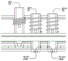
现在参照图6a至图6c,示意性地示出了锁定销5a、5b的可能的锁定构型。Referring now to Figures 6a to 6c, possible locking configurations of the locking pins 5a, 5b are schematically shown.
所述锁定销5a、5b的尺寸、所述锁定销之间的距离、下导轨中的孔口32a、32b的尺寸以及所述孔口之间的距离可以选择成使得获得“无夹紧式(chuckless)”接合。The dimensions of the locking pins 5a, 5b, the distance between the locking pins, the dimensions of the
在图6a中所示的第一可能的构型中,中间销5”穿入下导轨的孔口32”中并且与孔口32”的边缘的前侧部接合(主锁定),而前销5’穿入下导轨的在孔口32”紧前方的另一孔口32’中,并且前销5’与孔口32’的边缘的后侧部接合(副锁定);后销5”’未穿入下导轨的任何孔口中,而是抵靠两个相邻孔口(即孔口32”和后面的孔口)之间的连结板。In a first possible configuration shown in Figure 6a, the
在图6b中所示的第二可能的构型中,前销5’穿入下导轨的孔口32’中并且与孔口32’的边缘的前侧部接合(主锁定),而后销5”’穿入下导轨的在孔口32’紧后方的另一孔口32”中,并且后销5”’与孔口32”的边缘的后侧部接合(副锁定);中间销5”未插入下导轨的任何孔口中,而是抵靠两个相邻孔口(即孔口32’和孔口32”)之间的连结板。In a second possible configuration shown in Figure 6b, the
在图6c中所示的第三可能的构型中,后销5”’穿入下导轨的孔口32”中并且与孔口32”的边缘的前侧部接合(主锁定),而中间销5”穿入下导轨的在孔口32”紧前方的另一孔口32’中,并且中间销5”与孔口32’的边缘的后侧部接合(副锁定);前销5’未穿入下导轨的任何孔口中,而是抵靠两个相邻孔口(即孔口32’和前面的孔口)之间的连结板。In a third possible configuration shown in Figure 6c, the
仅以示例的方式给出了本发明的优选实施方式的以上描述,并且在不脱离由所附权利要求限定的本发明的范围的情况下,可以设想本领域技术人员可以完成的若干变型和改型。The foregoing description of the preferred embodiments of the present invention has been given by way of example only, and several variations and modifications can be envisaged by those skilled in the art without departing from the scope of the invention as defined by the appended claims. type.
Claims (11)
Applications Claiming Priority (3)
| Application Number | Priority Date | Filing Date | Title |
|---|---|---|---|
| IT102018000006569 | 2018-06-21 | ||
| IT102018000006569A IT201800006569A1 (en) | 2018-06-21 | 2018-06-21 | Sliding device for a vehicle seat having an improved locking system |
| PCT/IB2019/053183 WO2019243903A1 (en) | 2018-06-21 | 2019-04-17 | Sliding device for a vehicle seat provided with an improved locking arrangement |
Publications (2)
| Publication Number | Publication Date |
|---|---|
| CN110856444A true CN110856444A (en) | 2020-02-28 |
| CN110856444B CN110856444B (en) | 2021-02-12 |
Family
ID=63449617
Family Applications (1)
| Application Number | Title | Priority Date | Filing Date |
|---|---|---|---|
| CN201980002638.XA Active CN110856444B (en) | 2018-06-21 | 2019-04-17 | Sliding device provided with an improved locking device for a vehicle seat |
Country Status (14)
| Country | Link |
|---|---|
| US (1) | US11220194B2 (en) |
| EP (1) | EP3615372B1 (en) |
| JP (1) | JP6755419B2 (en) |
| KR (1) | KR102182183B1 (en) |
| CN (1) | CN110856444B (en) |
| AR (1) | AR115580A1 (en) |
| CA (1) | CA3102046C (en) |
| ES (1) | ES2836734T3 (en) |
| IT (1) | IT201800006569A1 (en) |
| MA (1) | MA51932B1 (en) |
| MX (1) | MX2020013793A (en) |
| RU (1) | RU2748980C1 (en) |
| TW (1) | TWI697420B (en) |
| WO (1) | WO2019243903A1 (en) |
Cited By (1)
| Publication number | Priority date | Publication date | Assignee | Title |
|---|---|---|---|---|
| US11835119B2 (en) | 2020-02-21 | 2023-12-05 | Lear Corporation | Track system with a support member |
Families Citing this family (9)
| Publication number | Priority date | Publication date | Assignee | Title |
|---|---|---|---|---|
| IT201800005731A1 (en) * | 2018-05-25 | 2019-11-25 | Slider for a vehicle seat | |
| IT201800006569A1 (en) * | 2018-06-21 | 2019-12-21 | Sliding device for a vehicle seat having an improved locking system | |
| IT201800006570A1 (en) | 2018-06-21 | 2019-12-21 | Sliding device for a vehicle seat having an improved locking system | |
| IT201800006650A1 (en) | 2018-06-26 | 2019-12-26 | Sliding device for a vehicle seat having an improved locking system | |
| IT201800007333A1 (en) | 2018-07-19 | 2020-01-19 | Slider for a vehicle seat equipped with an improved release assembly | |
| KR102295175B1 (en) | 2018-09-05 | 2021-08-30 | 마터 이탤리 에스알엘 | Sliding device for vehicle seats with improved locking mechanism |
| DE102020205818B3 (en) * | 2020-02-21 | 2021-06-24 | Adient Engineering and IP GmbH | Longitudinal adjuster for a seat, in particular a vehicle seat |
| KR102729601B1 (en) * | 2022-06-15 | 2024-11-14 | 주식회사 다스 | Locking device for seat rail |
| KR102847537B1 (en) * | 2023-05-19 | 2025-08-20 | 주식회사 다스 | Installation structure for track lever of seat rail |
Citations (7)
| Publication number | Priority date | Publication date | Assignee | Title |
|---|---|---|---|---|
| CN102198808A (en) * | 2010-03-25 | 2011-09-28 | 爱信精机株式会社 | Seat slide apparatus for vehicle |
| CN102227334A (en) * | 2008-12-18 | 2011-10-26 | 李尔公司 | Positive engagement locking system for vehicle seats |
| CN104553894A (en) * | 2014-12-31 | 2015-04-29 | 重庆延锋江森汽车部件系统有限公司 | Automobile seat slide rail |
| DE102014220476A1 (en) * | 2014-08-07 | 2016-02-11 | Johnson Controls Gmbh | Locking mechanism and longitudinal adjuster with locking mechanism |
| CN205440035U (en) * | 2014-12-30 | 2016-08-10 | 现代岱摩斯 | Device for locking a vehicle seat track |
| FR3032657A1 (en) * | 2015-02-17 | 2016-08-19 | Faurecia Sieges Automobile | SLIDE FOR VEHICLE SEAT AND VEHICLE SEAT COMPRISING SUCH A SLIDER |
| CN107000611A (en) * | 2014-12-12 | 2017-08-01 | 安道拓卢森堡控股有限公司 | Longitudinal adjuster and seat for seat |
Family Cites Families (34)
| Publication number | Priority date | Publication date | Assignee | Title |
|---|---|---|---|---|
| FR2736311B1 (en) * | 1995-07-04 | 1997-09-05 | Faure Bertrand Equipements Sa | LOCKABLE SLIDE IN POSITION FOR MOTOR VEHICLE SEATS |
| FR2768670B1 (en) * | 1997-09-25 | 1999-12-03 | Faure Bertrand Equipements Sa | ATTACHING A LOCK TO A MOTOR VEHICLE SEAT SLIDE PROFILE |
| US20030006355A1 (en) * | 2001-07-09 | 2003-01-09 | Horsfield Keith C. | Seat track assembly with locking mechanism |
| US6623363B2 (en) * | 2001-09-27 | 2003-09-23 | The Torrington Company | Universal joint yoke and method of making same |
| DE50211512D1 (en) * | 2001-11-28 | 2008-02-21 | Hammerstein Gmbh C Rob | Locking device with grooved locking pins |
| US6637712B1 (en) | 2002-05-17 | 2003-10-28 | Dura Global Technologies, Inc. | Automotive seat track lock mechanism with positive engagement |
| KR100512889B1 (en) * | 2003-05-27 | 2005-09-07 | 주식회사 오스템 | Locking device of seat-track for vehicles |
| JP2005067557A (en) * | 2003-08-28 | 2005-03-17 | Toyo Seat Co Ltd | Seat sliding device |
| DE20314237U1 (en) * | 2003-09-09 | 2005-01-13 | Brose Fahrzeugteile Gmbh & Co. Kg, Coburg | Memory device for a rail longitudinal guide of a motor vehicle |
| KR100610431B1 (en) * | 2004-10-02 | 2006-08-09 | 기아자동차주식회사 | Car Seat Slide |
| DE602005020491D1 (en) * | 2004-11-12 | 2010-05-20 | Johnson Controls Tech Co | VEHICLE SEAT GUIDE |
| FR2893277B1 (en) * | 2005-11-17 | 2009-05-29 | Faurecia Sieges Automobile | AUTOMOTIVE VEHICLE SEAT SLIDER, MOTOR VEHICLE SEAT AND MOTOR VEHICLE EQUIPPED WITH SUCH A SEAT |
| CA2637494A1 (en) * | 2006-02-27 | 2007-08-30 | Intier Automotive Inc. | Leaf spring track latch |
| DE102007027321A1 (en) | 2007-06-14 | 2009-02-05 | Brose Fahrzeugteile Gmbh & Co. Kommanditgesellschaft, Coburg | Locking device for a rail adjustment system |
| WO2009132944A1 (en) * | 2008-04-28 | 2009-11-05 | C. Rob. Hammerstein Gmbh & Co. Kg | Actuating unit of a motor vehicle seat |
| JP4947123B2 (en) * | 2009-11-04 | 2012-06-06 | アイシン精機株式会社 | Vehicle sliding device |
| US8382057B2 (en) * | 2010-03-31 | 2013-02-26 | Crh North America, Inc. | Low profile seat track system |
| CN102180108B (en) * | 2011-04-18 | 2012-12-12 | 湖北寒桦科技有限责任公司 | Seat slide rail |
| KR101206802B1 (en) * | 2011-04-21 | 2012-11-30 | 주식회사 오스템 | Seat track |
| KR101230850B1 (en) * | 2011-05-17 | 2013-02-07 | 주식회사다스 | Seat rail locking device of vehicle |
| TWM506740U (en) | 2012-07-06 | 2015-08-11 | Hsin Chong Machinery Works Co | Vehicle seat sliding rail locking device |
| FR2996180B1 (en) * | 2012-09-28 | 2016-10-28 | Faurecia Sieges Automobile | SLIDE FOR VEHICLE SEAT AND VEHICLE SEAT COMPRISING SUCH A SLIDER |
| KR101407259B1 (en) * | 2012-11-28 | 2014-06-13 | 현대다이모스(주) | Seat rail locking apparatus of vehicle |
| DE102014104295B4 (en) * | 2014-03-27 | 2016-12-15 | Faurecia Autositze Gmbh | Rail system for a vehicle seat |
| BR102017006962A2 (en) * | 2017-04-05 | 2018-10-30 | Aethra Sistemas Automotivos S/A | longitudinal movement and adjustment device of motor vehicle seats |
| CN207274475U (en) | 2017-09-07 | 2018-04-27 | 南京陈唱交通器材有限公司 | Adjusting part and Novel car seat before and after Novel car seat |
| KR102001502B1 (en) * | 2017-12-26 | 2019-07-18 | 현대트랜시스(주) | Seat rail for vehicle |
| IT201800005731A1 (en) | 2018-05-25 | 2019-11-25 | Slider for a vehicle seat | |
| IT201800006570A1 (en) | 2018-06-21 | 2019-12-21 | Sliding device for a vehicle seat having an improved locking system | |
| IT201800006569A1 (en) * | 2018-06-21 | 2019-12-21 | Sliding device for a vehicle seat having an improved locking system | |
| IT201800006650A1 (en) | 2018-06-26 | 2019-12-26 | Sliding device for a vehicle seat having an improved locking system | |
| IT201800007333A1 (en) | 2018-07-19 | 2020-01-19 | Slider for a vehicle seat equipped with an improved release assembly | |
| KR102295175B1 (en) * | 2018-09-05 | 2021-08-30 | 마터 이탤리 에스알엘 | Sliding device for vehicle seats with improved locking mechanism |
| IT201900000313A1 (en) | 2019-01-09 | 2020-07-09 | Martur Italy Srl | Slider for a vehicle seat with an improved rail configuration |
-
2018
- 2018-06-21 IT IT102018000006569A patent/IT201800006569A1/en unknown
-
2019
- 2019-04-17 CA CA3102046A patent/CA3102046C/en active Active
- 2019-04-17 RU RU2020139126A patent/RU2748980C1/en active
- 2019-04-17 EP EP19726490.6A patent/EP3615372B1/en active Active
- 2019-04-17 KR KR1020197037091A patent/KR102182183B1/en active Active
- 2019-04-17 CN CN201980002638.XA patent/CN110856444B/en active Active
- 2019-04-17 JP JP2019570470A patent/JP6755419B2/en active Active
- 2019-04-17 MA MA51932A patent/MA51932B1/en unknown
- 2019-04-17 ES ES19726490T patent/ES2836734T3/en active Active
- 2019-04-17 MX MX2020013793A patent/MX2020013793A/en unknown
- 2019-04-17 WO PCT/IB2019/053183 patent/WO2019243903A1/en not_active Ceased
- 2019-04-17 US US16/616,601 patent/US11220194B2/en active Active
- 2019-04-19 TW TW108113833A patent/TWI697420B/en active
- 2019-06-19 AR ARP190101693A patent/AR115580A1/en active IP Right Grant
Patent Citations (7)
| Publication number | Priority date | Publication date | Assignee | Title |
|---|---|---|---|---|
| CN102227334A (en) * | 2008-12-18 | 2011-10-26 | 李尔公司 | Positive engagement locking system for vehicle seats |
| CN102198808A (en) * | 2010-03-25 | 2011-09-28 | 爱信精机株式会社 | Seat slide apparatus for vehicle |
| DE102014220476A1 (en) * | 2014-08-07 | 2016-02-11 | Johnson Controls Gmbh | Locking mechanism and longitudinal adjuster with locking mechanism |
| CN107000611A (en) * | 2014-12-12 | 2017-08-01 | 安道拓卢森堡控股有限公司 | Longitudinal adjuster and seat for seat |
| CN205440035U (en) * | 2014-12-30 | 2016-08-10 | 现代岱摩斯 | Device for locking a vehicle seat track |
| CN104553894A (en) * | 2014-12-31 | 2015-04-29 | 重庆延锋江森汽车部件系统有限公司 | Automobile seat slide rail |
| FR3032657A1 (en) * | 2015-02-17 | 2016-08-19 | Faurecia Sieges Automobile | SLIDE FOR VEHICLE SEAT AND VEHICLE SEAT COMPRISING SUCH A SLIDER |
Cited By (1)
| Publication number | Priority date | Publication date | Assignee | Title |
|---|---|---|---|---|
| US11835119B2 (en) | 2020-02-21 | 2023-12-05 | Lear Corporation | Track system with a support member |
Also Published As
| Publication number | Publication date |
|---|---|
| CN110856444B (en) | 2021-02-12 |
| US11220194B2 (en) | 2022-01-11 |
| JP6755419B2 (en) | 2020-09-16 |
| KR102182183B1 (en) | 2020-11-25 |
| MX2020013793A (en) | 2021-03-02 |
| IT201800006569A1 (en) | 2019-12-21 |
| TW202000499A (en) | 2020-01-01 |
| CA3102046C (en) | 2021-05-18 |
| CA3102046A1 (en) | 2019-12-26 |
| EP3615372B1 (en) | 2020-09-09 |
| JP2020526434A (en) | 2020-08-31 |
| TWI697420B (en) | 2020-07-01 |
| MA51932B1 (en) | 2021-09-30 |
| EP3615372A1 (en) | 2020-03-04 |
| AR115580A1 (en) | 2021-02-03 |
| ES2836734T3 (en) | 2021-06-28 |
| RU2748980C1 (en) | 2021-06-02 |
| KR20200016267A (en) | 2020-02-14 |
| US20200391620A1 (en) | 2020-12-17 |
| MA51932A1 (en) | 2021-02-26 |
| BR112020025378A2 (en) | 2021-03-09 |
| WO2019243903A1 (en) | 2019-12-26 |
Similar Documents
| Publication | Publication Date | Title |
|---|---|---|
| CN110856444B (en) | Sliding device provided with an improved locking device for a vehicle seat | |
| KR102154460B1 (en) | Sliding device for vehicle seats with improved locking arrangement | |
| KR102295175B1 (en) | Sliding device for vehicle seats with improved locking mechanism | |
| JP3949671B2 (en) | Car seat runner | |
| CN110933940B (en) | Sliding device for a vehicle seat provided with an improved release assembly | |
| CN110869240B (en) | Sliding device provided with an improved locking structure for a vehicle seat | |
| BR112020025378B1 (en) | SLIDING DEVICE FOR A VEHICLE SEAT |
Legal Events
| Date | Code | Title | Description |
|---|---|---|---|
| PB01 | Publication | ||
| PB01 | Publication | ||
| SE01 | Entry into force of request for substantive examination | ||
| SE01 | Entry into force of request for substantive examination | ||
| GR01 | Patent grant | ||
| GR01 | Patent grant | ||
| TR01 | Transfer of patent right | ||
| TR01 | Transfer of patent right |
Effective date of registration: 20250725 Address after: Italy Patentee after: MFI Italy Engineering Co.,Ltd. Country or region after: Italy Address before: Milan Italy Patentee before: Mathur Italy Ltd. Country or region before: Italy |