Disclosure of Invention
The aim of the invention is to optimize the milling process as much as possible so that residues remaining in the milling chamber during the milling process can be removed from the milling chamber more quickly and more efficiently than is the case in the prior art.
The above object is achieved by a method and a device according to claims 1 and 11. Further embodiments of the invention emerge from the corresponding dependent claims.
The invention relates to a method for milling, separating and discharging difficult-to-grind components of a material mixture consisting of components having different milling properties from a process chamber of a jet mill. As the components contained in the material mixture have different properties, so that the fully comminuted particles, also referred to as fine material, leave the process chamber via the fine material outlet after classification. For example by means of a separating wheel. The hard-to-grind constituents, also called coarse fractions, cannot pass through the sorting mechanism and therefore remain in the process chamber. In order to avoid accumulation of the coarse fraction in the process chamber, the coarse fraction is discharged by means of a fluid via at least one discharge interface.
The fluid which is discharged from the process chamber with the coarse fraction is supplied via milling nozzles which project into the process chamber. The nozzles provide gas jets during the milling process by which the particles of the delivered material are comminuted. Due to the overpressure or underpressure in the process chamber, the coarse fraction is discharged from the process chamber by means of the grinding gas via at least one discharge connection.
In order to further optimize the method, the outlet connection is closed during the milling process toward the process chamber and is opened only in the coarse fraction discharge phase, either manually or automatically.
Another advantage of the method according to the invention is that the milled material delivery is interrupted manually or automatically. This prevents the supply of non-millable material to the milling chamber via the milled material inlet during the emptying of the milling chamber or during the discharge of the difficult-to-grind components from the milling chamber. By means of a metering unit, for example via an impeller valve; or a metering pump to feed the milled material into the process chamber via the milled material delivery.
The outlet connection and the milled material delivery can be closed off from the process chamber by means of a closure element. The blocking element can be configured, for example, as a gate, a slider or an impeller valve.
In order to be able to better regulate the interruption of the milled material delivery, at least one operating parameter of the method is detected via at least one sensor. Important operating parameters are, for example, the degree of filling of the mill; the amount and rate of milled material delivery and the amount, pressure and rate of milling fluid added; the rotational speed of the separator wheel and the power consumption of the motor driving the separator wheel and the yield of ground material.
The different parameters have an interaction with one another, in particular the degree of filling of the mill and the milled material delivery. The degree of filling of the mill is controlled via the power consumption of the separating wheel. If the ground grinding material leaves the process chamber via the separating wheel and the fine material outlet, there is a small amount of grinding material in the process chamber, so that the particles of grinding material rarely collide with the separating wheel. Thereby reducing the power required to maintain a constant rotational speed of the separator wheel and reducing the power consumption of the motor driving the separator wheel. If the power consumption deviates from a defined minimum value, for example, falls below 60% of the maximum power of the motor driving the separating wheel, the ground material is delivered into the process chamber via the ground material delivery section until the power consumption of the motor driving the separating wheel again reaches a defined maximum value, for example 65% of the maximum power of the motor driving the separating wheel, based on the number of collisions with the ground material which is raised again at this time. Depending on the delivered grinding material, the limit value of the power consumption of the motor driving the separating wheel can vary. For example, the minimum value can be between 30% and 80%, in particular between 40% and 60%. The maximum value of the power consumption of the motor driving the separator wheel may be between 50% and 100%, in particular between 60% and 80%.
The process for the delivery of milled material described in the preceding paragraph expresses a constant period in milled material without constituents that are difficult to grind or that are not grindable. If the interval between the end of the milled material delivery and the start of the milled material delivery is referred to and the duration of the milled material delivery appears approximately periodic. This is not the case in milled material with components that are difficult to grind or that are not grindable.
The accumulation of difficult to grind or non-grindable constituents of the grinding material results in fewer particles leaving the process chamber than desired. The power consumption of the motor driving the separating wheel is thereby not reduced below a defined minimum value as quickly as possible, thereby also entailing a delay in the delivery of the ground material. The hard-to-grind or non-grind-able components of the grinding material remaining in the process chamber also load the separating wheel, but they do not pass through the separating wheel, thereby not reducing the power consumption of the motor driving the separating wheel and increasing the interval between the stop of the delivery of the grinding material and the start of the delivery of the grinding material, as in normal grinding material without hard-to-grind or non-grind-able components. The duration of the delivery of the milled material is reduced, because after falling below a predetermined minimum value, the respective maximum value is achieved more quickly for the power consumption of the motor driving the separating wheel, because a greater number of particles remain in the process chamber.
A clearly reduced throughput can be seen with an increase in the milling duration by the described case of milled material with constituents which are difficult to grind or cannot be ground. The reduction in yield is preferably used as a control value for discharging difficult-to-grind or non-grindable components from the mill.
The milled material delivery is automatically stopped if it deviates from at least one defined value range of at least one monitored operating parameter, for example the production. Similarly to the milled material delivery, i.e. also depending on the operating parameters, the opening and closing of the discharge interface can be controlled. The interruption or start of the delivery of the ground material and the opening or closing of the discharge interface can also be coordinated with one another. For example, only the milled material delivery can be controlled via at least one operating parameter. The milled material delivery is interrupted if at least one operating parameter, for example the production rate, or the interval of material input deviates from the value range defined for it. In this connection, the outlet connections can be opened simultaneously or at different times. It is likewise conceivable that only the outlet connection is controlled via at least one operating parameter and that the milled material is delivered in a reaction dependent thereon. This makes it possible to automatically provide the milling process with conditions which are stable and which are adapted to the respective milling material. The respective value ranges of the operating parameters are selected as a function of the material and the grinding fluid.
The opening time of the outlet connection and the interruption of the milled material delivery are set individually as a function of the milled material. The opening time of the discharge interface is preferably 1 to 10 seconds. The interruption of the delivery of the milled material is preferably 1 to 10 seconds.
In an advantageous manner of the method, the opening of the outlet connection and the interruption of the milled material delivery as well as the closing of the outlet connection and the start of the milled material delivery take place in coordination with one another. In order to avoid the loss of ground material, it is advantageous to interrupt the ground material delivery before opening the outlet connection. As a result, the delivered material that has not yet been ground can be ground and the particles that have been ground to the target size in the process chamber can be discharged.
An exemplary flow of the method may be as follows:
1. since the fraction of the milled material which is difficult to grind or cannot be ground accumulates in the process chamber, at least one operating parameter deviates from a defined value range.
2. The milled material delivery is interrupted.
3. Grinding and discharging the ground material still in the process chamber.
4. The discharge interface is opened and the portion of the milled material that is difficult or not to be milled is discharged from the process chamber.
5. The discharge interface is closed.
6. The milled material delivery is started and the milling process is continued.
Preferably, some of the method steps described above have a defined duration, for example the duration of the part of the grindable part of the ground material still in the process chamber is ground and discharged is between one and five minutes, in particular between 1 and 60 seconds. The opening duration of the outlet connection is between one second and one minute, in particular between 1 and 10 seconds. A renewed delivery of ground material can be started as soon as the discharge interface is closed. The time between two method steps can be between 0.5 and 60 seconds, in particular between 0.5 and 5 seconds.
The method according to the invention is carried out by means of a spiral jet mill for acting on the material that can be partially comminuted and classified. Such a helical jet mill has a process chamber which is surrounded by a housing. At least two milling nozzles project into the process chamber, through which milling fluid is introduced into the process chamber during the milling process.
In the case of a spiral jet mill, the process chamber is designed rotationally symmetrically flat and round, with radially extending housing walls which are each delimited above and below by a circular surface, wherein the height of the cylinder is smaller than the diameter. The milling nozzles are arranged tangentially on the housing wall. Furthermore, the milling nozzle is arranged on a plane with a separating wheel, which is located in the middle of the process chamber. The separating wheel is likewise of rotationally symmetrical design, flat and round, with radially extending lamellae each defined by a flat plate designed as a circular surface lying above and below, wherein the height of the cylinder is also smaller than the diameter here.
The milling fluid is introduced into the process chamber through the milling nozzle with a set pressure varying between 0.1 and 40bar (g) depending on the milling material and the milling fluid. Typical milling fluids are air, nitrogen, water vapor and inert gases such as argon and helium.
The grinding material introduced via a grinding material inlet connected to the process chamber is captured by the grinding fluid jet, accelerated and comminuted by particle-particle collisions. Thereby involving naturally occurring grinding of the milled material. The particles that meet the requirements are transported by the grinding fluid to a separating wheel, which is driven via a motor, for example, of controllable frequency. The target fineness of the desired fine material is preset via the rotational speed of the separating wheel. The fine material is discharged from the machine via a fine material outlet after passing through the separating wheel. The particles that are too coarse or not yet sufficiently ground are pushed away by the separating wheel and thus reach again into the product-laden grinding fluid jet to reload the load. Thereby generating a circular movement of the milled material in the process chamber.
In order to remove the part of the milled material that accumulates in the process chamber, which is a component that is difficult or impossible to grind, from the process chamber, a discharge connection is provided that is connected to the process chamber. The outlet connection can be closed manually or automatically with respect to the process chamber and closed during the milling process.
The machine according to the invention for acting on partially comminuted and sorted material has a measuring device which detects an operating parameter of the grinding process. Important operating parameters are, for example, the milled material yield per time unit, the quantity and speed of milled material delivery, the quantity, pressure and speed of the milling fluid fed, the rotational speed of the separating wheel and the power consumption of the motor driving the separating wheel. Furthermore, the machine according to the invention comprises means for detecting and controlling the metering of the ground material into the process chamber.
The method may include one or more of the features and/or characteristics of the apparatus described above, in place of or in addition to the features described. Also alternatively or additionally, the apparatus may have single or multiple features and/or characteristics of the method.
It should be emphasized here that all the variants and variants mentioned in connection with the output mixture according to the invention and the device for producing the output mixture can equally relate to part of the method according to the invention. The same therefore applies to the method according to the invention, when particular aspects and/or relationships and/or actions are mentioned here in the description or in the claims for the output mixture and/or device according to the invention. On the contrary, the same holds true, so that all variants and variants described in connection with the method according to the invention can equally relate to partial variants of the output mixture and the device according to the invention. The same therefore applies to the output mixture and the device according to the invention, when particular aspects and/or relationships and/or functions are mentioned here in the description or in the claims for the method according to the invention.
Detailed Description
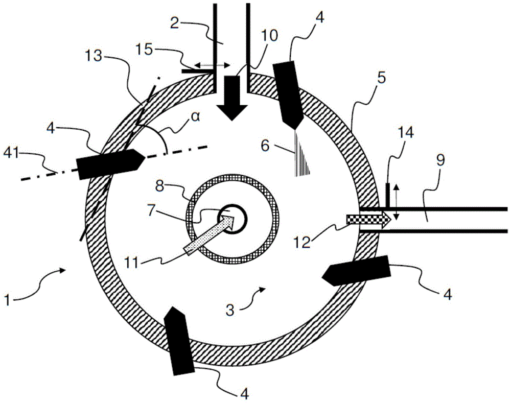
Fig. 1 shows a sectional view of a screw jet mill 1 with a milled material delivery 2, through which milled material 10 is introduced into a process chamber 3. Via a metering unit (not shown), such as an impeller valve; or a pump device to meter, i.e. deliver, the ground material 10.
Milling nozzles 4, which are positioned at a suitable distance from one another, project into the process chamber 3. The suitable distance is selected as a function of the number of milling nozzles 4 and can be selected in such a way that the milling nozzles 4 are distributed uniformly on a circular path representing the housing 5 surrounding the process chamber 3, i.e. in the example of fig. 1 the milling nozzles 4 are each arranged offset by 90 ° and their respective longitudinal axes 41 enclose an angle Alpha (α) with a tangent 13 provided in the region of the respective milling nozzle holder in the housing 5, the angle Alpha (α) being in the range of 10 ° and 60 °.
The milling nozzles 4 can also be arranged irregularly on the housing 5, as regards the application.
The milling nozzle 4 delivers milling fluid 6 to the process chamber 3. The grinding fluid 6 serves to load and pulverize the outgoing grinding material 10. Parameters such as pressure, quantity, temperature and spray angle for the grinding fluid 6 are adjusted depending on the application and the delivered grinding material 10. Gases, in particular protective gases such as argon, helium and nitrogen, are conceivable as milling fluid 6, for example.
A fine material outlet 7 is located in the middle of the process chamber 3, which leads the particles away from the process chamber 3 through the top or bottom of the housing 5. The particles, which have been ground in the process chamber 3 to the desired fineness, i.e. the ground fraction of the grinding material 11, are discharged through the fine material outlet 7. In order to be able to leave only particles of the desired fineness out of the process chamber 3, a separating wheel 8 is positioned around the fine material outlet 7. The separator wheel 8 rotates and runs at a variable rotational speed. Thus, a desired fineness can be set for the ground portion of the milled material 11. If too large particles are to pass the rotating separating wheel 8, the particles will be thrown back into the process chamber 3 by the separating wheel 8 and be reloaded. If the particles are ground sufficiently fine so that they have a sufficiently small particle size or particle size, the particles can leave the process chamber 3 through the fine material outlet 7 with the fluid flow of the ground portion of the milled material 11.
The difficult-to-grind or non-grindable part of the milled material 12 therefore remains in the process chamber 3 and accumulates in the course of the milling process. In order to discharge the particles from the process chamber 3, the milled material delivery 2 is closed relative to the process chamber 3. Simultaneously or with a defined time offset, the outlet connection 9 is opened. The discharge interface is closed during the milling process by a blocking element 14, for example a shutter; or the glider is closed with respect to the process chamber 3. The blocking element 14 can optionally be positioned in the outlet port 9, for example, the blocking element 14 can rest flush against the outer cover of the housing 5; or may be mounted within the housing 5 and closed flush with the process chamber 3. By means of an overpressure or underpressure in the process chamber 3 of from-500 mbar (g) to +600mbar (g), all particles in the process chamber 3 are now flushed out of the process chamber 3 via the outlet connection 9.
After a time of, for example, 1 to 60 seconds or after a sensor which monitors the degree of filling in the process chamber 3 and thus checks whether all the difficult-to-grind or non-grindable parts of the milled material 2 have been discharged from the process chamber has issued a report, the discharge connection 9 is closed again by means of the closure element 14. The milled material delivery 2 is then opened or started again and the milling process is continued.
It can optionally also be provided that the milled material delivery 2 is closed off from the process chamber 3 by means of a further closing element similar to the closing element 14 in the outlet connection 9.
List of reference numerals
1 spiral jet mill
2 grinding material delivery part
3 Process chamber
4 milling nozzle
5 casing
6 milling fluid
7 fine material outlet
8 separating wheel
9 discharge interface
10 grinding material
11 grinding fraction of ground material
12 difficult to grind or non-grindable portions of the material to be ground
13 tangent line
14 blocking element
41 longitudinal axis of milling nozzle