CN110872019A - Sheet post-processing device and image forming system including the same - Google Patents
Sheet post-processing device and image forming system including the same Download PDFInfo
- Publication number
- CN110872019A CN110872019A CN201910783508.6A CN201910783508A CN110872019A CN 110872019 A CN110872019 A CN 110872019A CN 201910783508 A CN201910783508 A CN 201910783508A CN 110872019 A CN110872019 A CN 110872019A
- Authority
- CN
- China
- Prior art keywords
- sheet
- holder
- sheets
- paper
- processing
- Prior art date
- Legal status (The legal status is an assumption and is not a legal conclusion. Google has not performed a legal analysis and makes no representation as to the accuracy of the status listed.)
- Granted
Links
Images


Classifications
-
- B—PERFORMING OPERATIONS; TRANSPORTING
- B65—CONVEYING; PACKING; STORING; HANDLING THIN OR FILAMENTARY MATERIAL
- B65H—HANDLING THIN OR FILAMENTARY MATERIAL, e.g. SHEETS, WEBS, CABLES
- B65H37/00—Article or web delivery apparatus incorporating devices for performing specified auxiliary operations
- B65H37/04—Article or web delivery apparatus incorporating devices for performing specified auxiliary operations for securing together articles or webs, e.g. by adhesive, stitching or stapling
-
- B—PERFORMING OPERATIONS; TRANSPORTING
- B65—CONVEYING; PACKING; STORING; HANDLING THIN OR FILAMENTARY MATERIAL
- B65H—HANDLING THIN OR FILAMENTARY MATERIAL, e.g. SHEETS, WEBS, CABLES
- B65H29/00—Delivering or advancing articles from machines; Advancing articles to or into piles
- B65H29/20—Delivering or advancing articles from machines; Advancing articles to or into piles by contact with rotating friction members, e.g. rollers, brushes, or cylinders
- B65H29/22—Delivering or advancing articles from machines; Advancing articles to or into piles by contact with rotating friction members, e.g. rollers, brushes, or cylinders and introducing into a pile
-
- B—PERFORMING OPERATIONS; TRANSPORTING
- B65—CONVEYING; PACKING; STORING; HANDLING THIN OR FILAMENTARY MATERIAL
- B65H—HANDLING THIN OR FILAMENTARY MATERIAL, e.g. SHEETS, WEBS, CABLES
- B65H29/00—Delivering or advancing articles from machines; Advancing articles to or into piles
- B65H29/12—Delivering or advancing articles from machines; Advancing articles to or into piles by means of the nip between two, or between two sets of, moving tapes or bands or rollers
- B65H29/125—Delivering or advancing articles from machines; Advancing articles to or into piles by means of the nip between two, or between two sets of, moving tapes or bands or rollers between two sets of rollers
-
- B—PERFORMING OPERATIONS; TRANSPORTING
- B65—CONVEYING; PACKING; STORING; HANDLING THIN OR FILAMENTARY MATERIAL
- B65H—HANDLING THIN OR FILAMENTARY MATERIAL, e.g. SHEETS, WEBS, CABLES
- B65H31/00—Pile receivers
- B65H31/02—Pile receivers with stationary end support against which pile accumulates
-
- B—PERFORMING OPERATIONS; TRANSPORTING
- B65—CONVEYING; PACKING; STORING; HANDLING THIN OR FILAMENTARY MATERIAL
- B65H—HANDLING THIN OR FILAMENTARY MATERIAL, e.g. SHEETS, WEBS, CABLES
- B65H31/00—Pile receivers
- B65H31/34—Apparatus for squaring-up piled articles
-
- B—PERFORMING OPERATIONS; TRANSPORTING
- B65—CONVEYING; PACKING; STORING; HANDLING THIN OR FILAMENTARY MATERIAL
- B65H—HANDLING THIN OR FILAMENTARY MATERIAL, e.g. SHEETS, WEBS, CABLES
- B65H31/00—Pile receivers
- B65H31/34—Apparatus for squaring-up piled articles
- B65H31/36—Auxiliary devices for contacting each article with a front stop as it is piled
-
- B—PERFORMING OPERATIONS; TRANSPORTING
- B65—CONVEYING; PACKING; STORING; HANDLING THIN OR FILAMENTARY MATERIAL
- B65H—HANDLING THIN OR FILAMENTARY MATERIAL, e.g. SHEETS, WEBS, CABLES
- B65H43/00—Use of control, checking, or safety devices, e.g. automatic devices comprising an element for sensing a variable
- B65H43/08—Photoelectric devices
-
- G—PHYSICS
- G03—PHOTOGRAPHY; CINEMATOGRAPHY; ANALOGOUS TECHNIQUES USING WAVES OTHER THAN OPTICAL WAVES; ELECTROGRAPHY; HOLOGRAPHY
- G03G—ELECTROGRAPHY; ELECTROPHOTOGRAPHY; MAGNETOGRAPHY
- G03G15/00—Apparatus for electrographic processes using a charge pattern
- G03G15/65—Apparatus which relate to the handling of copy material
- G03G15/6538—Devices for collating sheet copy material, e.g. sorters, control, copies in staples form
- G03G15/6541—Binding sets of sheets, e.g. by stapling, glueing
-
- B—PERFORMING OPERATIONS; TRANSPORTING
- B65—CONVEYING; PACKING; STORING; HANDLING THIN OR FILAMENTARY MATERIAL
- B65H—HANDLING THIN OR FILAMENTARY MATERIAL, e.g. SHEETS, WEBS, CABLES
- B65H2301/00—Handling processes for sheets or webs
- B65H2301/40—Type of handling process
- B65H2301/42—Piling, depiling, handling piles
- B65H2301/421—Forming a pile
- B65H2301/4212—Forming a pile of articles substantially horizontal
-
- B—PERFORMING OPERATIONS; TRANSPORTING
- B65—CONVEYING; PACKING; STORING; HANDLING THIN OR FILAMENTARY MATERIAL
- B65H—HANDLING THIN OR FILAMENTARY MATERIAL, e.g. SHEETS, WEBS, CABLES
- B65H2301/00—Handling processes for sheets or webs
- B65H2301/40—Type of handling process
- B65H2301/42—Piling, depiling, handling piles
- B65H2301/421—Forming a pile
- B65H2301/4213—Forming a pile of a limited number of articles, e.g. buffering, forming bundles
-
- B—PERFORMING OPERATIONS; TRANSPORTING
- B65—CONVEYING; PACKING; STORING; HANDLING THIN OR FILAMENTARY MATERIAL
- B65H—HANDLING THIN OR FILAMENTARY MATERIAL, e.g. SHEETS, WEBS, CABLES
- B65H2404/00—Parts for transporting or guiding the handled material
- B65H2404/10—Rollers
- B65H2404/15—Roller assembly, particular roller arrangement
- B65H2404/152—Arrangement of roller on a movable frame
- B65H2404/1521—Arrangement of roller on a movable frame rotating, pivoting or oscillating around an axis, e.g. parallel to the roller axis
-
- B—PERFORMING OPERATIONS; TRANSPORTING
- B65—CONVEYING; PACKING; STORING; HANDLING THIN OR FILAMENTARY MATERIAL
- B65H—HANDLING THIN OR FILAMENTARY MATERIAL, e.g. SHEETS, WEBS, CABLES
- B65H2404/00—Parts for transporting or guiding the handled material
- B65H2404/60—Other elements in face contact with handled material
- B65H2404/63—Oscillating, pivoting around an axis parallel to face of material, e.g. diverting means
-
- B—PERFORMING OPERATIONS; TRANSPORTING
- B65—CONVEYING; PACKING; STORING; HANDLING THIN OR FILAMENTARY MATERIAL
- B65H—HANDLING THIN OR FILAMENTARY MATERIAL, e.g. SHEETS, WEBS, CABLES
- B65H2405/00—Parts for holding the handled material
- B65H2405/10—Cassettes, holders, bins, decks, trays, supports or magazines for sheets stacked substantially horizontally
- B65H2405/11—Parts and details thereof
- B65H2405/111—Bottom
- B65H2405/1115—Bottom with surface inclined, e.g. in width-wise direction
- B65H2405/11151—Bottom with surface inclined, e.g. in width-wise direction with surface inclined upwardly in transport direction
-
- B—PERFORMING OPERATIONS; TRANSPORTING
- B65—CONVEYING; PACKING; STORING; HANDLING THIN OR FILAMENTARY MATERIAL
- B65H—HANDLING THIN OR FILAMENTARY MATERIAL, e.g. SHEETS, WEBS, CABLES
- B65H2405/00—Parts for holding the handled material
- B65H2405/10—Cassettes, holders, bins, decks, trays, supports or magazines for sheets stacked substantially horizontally
- B65H2405/11—Parts and details thereof
- B65H2405/111—Bottom
- B65H2405/1115—Bottom with surface inclined, e.g. in width-wise direction
- B65H2405/11152—Bottom with surface inclined, e.g. in width-wise direction with surface inclined downwardly in transport direction
-
- B—PERFORMING OPERATIONS; TRANSPORTING
- B65—CONVEYING; PACKING; STORING; HANDLING THIN OR FILAMENTARY MATERIAL
- B65H—HANDLING THIN OR FILAMENTARY MATERIAL, e.g. SHEETS, WEBS, CABLES
- B65H2408/00—Specific machines
- B65H2408/10—Specific machines for handling sheet(s)
- B65H2408/12—Specific machines for handling sheet(s) stapler arrangement
- B65H2408/122—Specific machines for handling sheet(s) stapler arrangement movable stapler
- B65H2408/1222—Specific machines for handling sheet(s) stapler arrangement movable stapler movable transversely to direction of transport
-
- B—PERFORMING OPERATIONS; TRANSPORTING
- B65—CONVEYING; PACKING; STORING; HANDLING THIN OR FILAMENTARY MATERIAL
- B65H—HANDLING THIN OR FILAMENTARY MATERIAL, e.g. SHEETS, WEBS, CABLES
- B65H2511/00—Dimensions; Position; Numbers; Identification; Occurrences
- B65H2511/10—Size; Dimensions
- B65H2511/13—Thickness
-
- B—PERFORMING OPERATIONS; TRANSPORTING
- B65—CONVEYING; PACKING; STORING; HANDLING THIN OR FILAMENTARY MATERIAL
- B65H—HANDLING THIN OR FILAMENTARY MATERIAL, e.g. SHEETS, WEBS, CABLES
- B65H2511/00—Dimensions; Position; Numbers; Identification; Occurrences
- B65H2511/20—Location in space
- B65H2511/21—Angle
- B65H2511/212—Rotary position
-
- B—PERFORMING OPERATIONS; TRANSPORTING
- B65—CONVEYING; PACKING; STORING; HANDLING THIN OR FILAMENTARY MATERIAL
- B65H—HANDLING THIN OR FILAMENTARY MATERIAL, e.g. SHEETS, WEBS, CABLES
- B65H2511/00—Dimensions; Position; Numbers; Identification; Occurrences
- B65H2511/30—Numbers, e.g. of windings or rotations
-
- B—PERFORMING OPERATIONS; TRANSPORTING
- B65—CONVEYING; PACKING; STORING; HANDLING THIN OR FILAMENTARY MATERIAL
- B65H—HANDLING THIN OR FILAMENTARY MATERIAL, e.g. SHEETS, WEBS, CABLES
- B65H2553/00—Sensing or detecting means
- B65H2553/60—Details of intermediate means between the sensing means and the element to be sensed
- B65H2553/61—Mechanical means, e.g. contact arms
-
- B—PERFORMING OPERATIONS; TRANSPORTING
- B65—CONVEYING; PACKING; STORING; HANDLING THIN OR FILAMENTARY MATERIAL
- B65H—HANDLING THIN OR FILAMENTARY MATERIAL, e.g. SHEETS, WEBS, CABLES
- B65H2701/00—Handled material; Storage means
- B65H2701/10—Handled articles or webs
- B65H2701/11—Dimensional aspect of article or web
- B65H2701/113—Size
- B65H2701/1131—Size of sheets
-
- B—PERFORMING OPERATIONS; TRANSPORTING
- B65—CONVEYING; PACKING; STORING; HANDLING THIN OR FILAMENTARY MATERIAL
- B65H—HANDLING THIN OR FILAMENTARY MATERIAL, e.g. SHEETS, WEBS, CABLES
- B65H2801/00—Application field
- B65H2801/03—Image reproduction devices
-
- B—PERFORMING OPERATIONS; TRANSPORTING
- B65—CONVEYING; PACKING; STORING; HANDLING THIN OR FILAMENTARY MATERIAL
- B65H—HANDLING THIN OR FILAMENTARY MATERIAL, e.g. SHEETS, WEBS, CABLES
- B65H2801/00—Application field
- B65H2801/24—Post -processing devices
- B65H2801/27—Devices located downstream of office-type machines
Landscapes
- Engineering & Computer Science (AREA)
- Mechanical Engineering (AREA)
- Textile Engineering (AREA)
- Physics & Mathematics (AREA)
- General Physics & Mathematics (AREA)
- Pile Receivers (AREA)
- Folding Of Thin Sheet-Like Materials, Special Discharging Devices, And Others (AREA)
Abstract
本发明提供可以抑制处理盘上的薄片体的整合不良的薄片体后处理装置以及具备该装置的图像形成系统。薄片体后处理装置包括处理盘、整合处理盘上的纸的整合构件、可旋转地支撑整合构件的可摇动的支架、使支架摇动的摇动机构以及控制摇动机构的控制部。摇动机构具有旋转轴,所述旋转轴在旋转方向具有游隙地插入支架的轴插入部。控制部使旋转轴旋转并停止在与重叠放置在处理盘上的薄片体的叠放高度对应的规定的旋转角度位置,将支架配置在接触位置。支架被允许在接触位置上相对于旋转轴在规定的游隙的范围内向退避方向的摇动。游隙的范围设定为与薄片体的叠放高度成比例地增大。
The present invention provides a sheet post-processing apparatus capable of suppressing misalignment of sheets on a processing tray, and an image forming system including the apparatus. The sheet post-processing apparatus includes a processing tray, an aligning member for aligning sheets on the processing tray, a swingable holder for rotatably supporting the alignment member, a rocking mechanism for rocking the holder, and a control unit for controlling the rocking mechanism. The rocking mechanism has a rotation shaft inserted into the shaft insertion portion of the holder with play in the rotation direction. The control unit rotates the rotating shaft and stops it at a predetermined rotational angle position corresponding to the stacking height of the sheets stacked on the processing tray, and arranges the holder at the contact position. The holder is allowed to oscillate in the retraction direction within a predetermined play range with respect to the rotating shaft at the contact position. The range of the play is set to increase in proportion to the stacking height of the sheets.
Description
技术领域technical field
本发明涉及在由复印机、传真机、打印机等图像形成装置形成了图像的纸等薄片体上进行后处理的薄片体后处理装置以及具备该装置的图像形成系统。The present invention relates to a sheet post-processing apparatus for post-processing a sheet such as paper on which an image has been formed by an image forming apparatus such as a copier, a facsimile machine, or a printer, and an image forming system including the apparatus.
背景技术Background technique
过去,已知有一种纸后处理装置,能够执行将通过复印机、打印机等图像形成装置形成了图像的纸(薄片体)多张堆叠,并将堆叠的纸整合成摞用订书钉进行装订的装订处理,以及用冲孔形成装置冲孔(穿孔)的冲孔形成处理等后处理。In the past, there has been known a paper post-processing device capable of stacking a plurality of sheets (sheets) of which an image has been formed by an image forming apparatus such as a copier or a printer, and integrating the stacked sheets into a bundle for binding with staples Binding processing, and post processing such as punch forming processing of punching (piercing) with a punch forming device.
在像这样的纸后处理装置中,设置了叠放规定张数的形成了图像的纸的处理盘、通过接触处理盘上最上面的纸的上表面并旋转将纸整合到输送方向的整合构件、能够旋转支撑整合构件的可摇动的支架以及使支架摇动的摇动机构。接着,对处理盘上的纸摞进行装订处理以及移位排出处理等。In such a paper post-processing device, a processing tray on which a predetermined number of image-formed sheets are stacked is provided, and an aligning member that aligns the paper in the conveying direction by contacting the upper surface of the uppermost sheet on the processing tray and rotating , a swingable bracket capable of rotatably supporting the integration member, and a swing mechanism for swinging the bracket. Next, a binding process, a shift discharge process, and the like are performed on the sheet bundle on the processing tray.
支架能够在整合构件与处理盘上的最上面的纸的上表面接触的接触位置以及整合构件从处理盘退避的退避位置之间摇动。为了避免整合构件对纸过度地按压,支架能够在配置于接触位置的状态下仅以规定角度向退避方向摇动(即,有游隙)。The holder is swingable between a contact position where the alignment member comes into contact with the upper surface of the uppermost sheet on the processing tray and a retracted position where the alignment member is retracted from the processing tray. In order to prevent the aligning member from pressing the paper excessively, the holder can be swung in the retracting direction only by a predetermined angle (ie, there is a play) in the state of being arranged at the contact position.
但是,在现有的纸后处理装置中,由于支架在配置于接触位置的状态下仅以规定角度向退避方向摇动(即,有游隙),所有当后续的纸的后端(或者前端)与支架抵接时,支架被向退避方向推升。接着,当后续的纸的后端(或者前端)通过支架的下方时,支架因自重回到接触位置。However, in the conventional paper post-processing device, since the holder oscillates in the retracting direction only at a predetermined angle (that is, there is a play) when the holder is arranged at the contact position, the rear end (or the front end) of the subsequent paper is always affected. When it comes into contact with the holder, the holder is pushed up in the retracting direction. Then, when the rear end (or the front end) of the subsequent paper passes under the bracket, the bracket returns to the contact position due to its own weight.
其中,在处理盘上的纸的张数较少的情况下,与纸的张数较多的情况相比,后续的纸使支架的摇动角度变大。因此,存在如下问题:在处理盘上的纸的张数较少的情况下,支架由于自重向接触位置返回时整合构件与纸的上表面强力抵接,因此对纸施加的输送力增大,导致纸的后端部弯曲,容易发生整合不良。However, when the number of sheets on the processing tray is small, the swing angle of the holder becomes larger for subsequent sheets than when the number of sheets is large. Therefore, when the number of sheets of paper on the processing tray is small, the aligning member strongly abuts the upper surface of the paper when the holder returns to the contact position due to its own weight, so that the conveying force applied to the paper increases, As a result, the rear end of the paper is bent and misalignment is likely to occur.
发明内容SUMMARY OF THE INVENTION
为了解决上述问题,本发明的目的在于提供能够抑制处理盘上薄片体整合不良的薄片体后处理装置以及具备该装置的图像形成系统。In order to solve the above-mentioned problems, an object of the present invention is to provide a sheet post-processing apparatus capable of suppressing poor alignment of sheets on a processing tray, and an image forming system including the apparatus.
本发明提供一种薄片体后处理装置,其包括:输送构件,输送薄片体;处理盘,配置在所述输送构件的薄片体输送方向的下游侧,具有接受所述薄片体并重叠放置的薄片体放置面;排出盘,设置在所述处理盘的薄片体排出方向下游侧;处理部,对所述处理盘上的所述薄片体进行后处理;整合构件,与所述处理盘上的薄片体的最上面的薄片体的上表面接触,将所述处理盘上的所述薄片体在薄片体排出方向上进行整合;支撑所述整合构件的能够摇动的支架;摇动机构,使所述支架摇动;以及控制部,控制所述摇动机构,所述支架能够在所述整合构件与所述薄片体的最上面的薄片体的上表面接触的接触位置和所述整合构件从所述薄片体的最上面的薄片体的上表面退避的退避位置之间摇动,所述摇动机构具有:旋转轴,在旋转方向上有游隙地插入所述支架的轴插入部并成为所述支架的摇动中心;以及驱动部,使所述旋转轴旋转,所述控制部使所述旋转轴旋转并使其停止在与重叠放置在所述处理盘上的所述薄片体的叠放高度对应的规定的旋转角度位置,将所述支架配置在所述接触位置,所述支架被允许在所述接触位置上相对于所述旋转轴在规定的游隙的范围内向退避方向摇动,所述游隙的范围设定为与所述薄片体的叠放高度成比例地变大。The present invention provides a sheet post-processing device, comprising: a conveying member for conveying sheets; and a processing tray disposed on the downstream side of the conveying member in the sheet conveying direction, and having sheets that receive the sheets and are stacked and placed. A body placement surface; a discharge tray provided on the downstream side of the processing tray in the sheet discharge direction; a processing section for post-processing the sheets on the processing tray; an aligning member with the sheets on the processing tray The upper surface of the uppermost sheet of the body is contacted, and the sheet on the processing tray is aligned in the sheet discharge direction; a swingable bracket supporting the integration member; a swing mechanism to make the bracket rocking; and a control section that controls the rocking mechanism, the bracket is capable of contacting the integrating member with the upper surface of the uppermost sheet body of the sheet body and the contact position of the integrating member from the sheet body The uppermost sheet is oscillated between retracted positions where the upper surface of the uppermost sheet body is retracted, and the rocking mechanism has a rotating shaft that is inserted into the shaft insertion portion of the holder with play in the rotational direction and serves as a pivoting center of the holder; and a drive unit that rotates the rotating shaft, and the control unit rotates the rotating shaft and stops it at a predetermined rotational angle position corresponding to a stacking height of the sheets stacked on the processing tray , the bracket is arranged at the contact position, and the bracket is allowed to oscillate in the retraction direction relative to the rotating shaft within a range of a predetermined clearance at the contact position, and the range of the clearance is set as It becomes larger in proportion to the stacking height of the sheets.
本发明还提供一种薄片体后处理装置,其包括:输送构件,输送薄片体;处理盘,配置在所述输送构件的薄片体输送方向的下游侧,具有接受所述薄片体并重叠放置的薄片体放置面;处理部,对所述处理盘上的所述薄片体进行规定的处理;整合构件,与重叠放置在所述处理盘上的薄片体的最上面的薄片体的上表面接触,将所述处理盘上的所述薄片体在薄片体排出方向上进行整合;支架,支撑所述整合构件;摇动机构,使所述支架摇动;以及控制部,控制所述摇动机构,所述支架能够在所述整合构件与所述薄片体的最上面的薄片体的上表面接触的接触位置和所述整合构件从所述薄片体的最上面的薄片体的上表面退避的退避位置之间摇动,所述摇动机构具有:旋转轴,在旋转方向上有游隙地插入所述支架的轴插入部并成为所述支架的摇动中心;以及驱动部,使所述旋转轴旋转,所述控制部使所述旋转轴旋转并使其停止在与重叠放置在所述处理盘上的所述薄片体的叠放高度对应的规定的旋转角度位置,将所述支架配置在所述接触位置,所述支架被允许在所述接触位置上相对于所述旋转轴在规定的游隙的范围内向退避方向摇动。The present invention also provides a sheet post-processing device, which includes: a conveying member for conveying the sheet; a processing tray disposed on the downstream side of the conveying member in the sheet conveying direction, and having a sheet receiving and overlapping the sheet. a sheet placement surface; a processing unit for performing predetermined processing on the sheet on the processing tray; an alignment member for contacting the upper surface of the uppermost sheet stacked on the processing tray, the sheet on the processing tray is aligned in the sheet discharge direction; a holder for supporting the alignment member; a rocking mechanism for rocking the holder; and a control unit for controlling the rocking mechanism, the holder The alignment member can be rocked between a contact position where the alignment member comes into contact with the upper surface of the uppermost sheet of the sheet and a retracted position where the alignment member is retracted from the upper surface of the uppermost sheet of the sheet and the rocking mechanism has: a rotating shaft that is inserted into a shaft insertion portion of the holder with play in the rotational direction to serve as a rocking center of the holder; and a driving portion that rotates the rotating shaft, and the control portion makes The rotating shaft is rotated and stopped at a predetermined rotational angle position corresponding to the stacking height of the sheets stacked on the processing tray, the holder is arranged at the contact position, and the holder is The contact position is allowed to oscillate in the retraction direction with respect to the rotating shaft within a range of a predetermined play.
本发明提供一种图像形成系统,包括图像形成装置,所述图像形成装置与上述构成的薄片体后处理装置连接,在薄片体上形成图像并且将形成有图像的所述薄片体输送到所述薄片体后处理装置。The present invention provides an image forming system including an image forming apparatus connected to the sheet post-processing apparatus configured as described above, forming an image on a sheet and conveying the sheet on which the image is formed to the Sheet post-processing device.
按照本发明的薄片体后处理装置,控制部在处理盘上的薄片体的张数较少的情况下,与薄片体的张数较多的情况相比,以减小向支架的退避方向的游隙的方式将旋转轴配置在规定的旋转角度位置。由此,在处理盘上的薄片体的张数较少的情况下,可以减小当后续的薄片体的后端(或者前端)与支架抵接并推起支架时的摇动角度。因此,后续的薄片体的后端(或者前端)通过支架的下方且支架向接触位置返回时,可以抑制整合构件对薄片体的上表面强力地抵接。由此,可以抑制施加到薄片体的输送力增大而导致薄片体弯曲,所以可以抑制发生整合不良。According to the sheet post-processing apparatus of the present invention, when the number of sheets on the processing tray is small, the control unit reduces the amount of time required in the retraction direction of the holder compared to when the number of sheets is large. The backlash method arranges the rotary shaft at a predetermined rotational angle position. Accordingly, when the number of sheets on the processing tray is small, the swing angle when the rear end (or front end) of the subsequent sheet comes into contact with the holder and the holder is pushed up can be reduced. Therefore, when the rear end (or front end) of the subsequent sheet passes under the holder and the holder returns to the contact position, the aligning member can be prevented from strongly abutting against the upper surface of the sheet. As a result, it is possible to prevent the sheet body from being bent due to an increase in the conveying force applied to the sheet body, so that the occurrence of misalignment can be suppressed.
此外,在处理盘上的薄片体的张数较多的情况下,由于薄片体摞的弹性增强,有时会由于因薄片体摞的弯曲等导致整合构件对薄片体过剩地度按压。但在本发明提供的薄片体后处理装置中,由于在处理盘上的薄片体的张数较多的情况下与薄片体的张数较少的情况下相比、向支架的退避方向的游隙增大,所以可以抑制整合构件对薄片体过度按压。In addition, when the number of sheets on the processing tray is large, since the elasticity of the sheet bundle increases, the alignment member may press the sheets excessively due to bending of the sheet bundle or the like. However, in the sheet post-processing apparatus provided by the present invention, when the number of sheets on the processing tray is large, compared with the case where the number of sheets is small, the movement in the retracting direction of the holder Since the gap increases, excessive pressing of the sheet body by the alignment member can be suppressed.
本发明其他的目的以及通过本发明可以得到的具体的优点,根据以下的实施方式的说明会更加明确。Other objects of the present invention and specific advantages obtained by the present invention will become clearer from the description of the following embodiments.
附图说明Description of drawings
图1是表示图像形成装置以及本发明的一个实施方式的纸后处理装置的内部构成的概略图。FIG. 1 is a schematic diagram showing the internal configuration of an image forming apparatus and a paper post-processing apparatus according to an embodiment of the present invention.
图2是表示本发明的一个实施方式的纸后处理装置的处理盘周边的构造的断面图。2 is a cross-sectional view showing a structure around a processing tray of the paper post-processing apparatus according to the embodiment of the present invention.
图3是表示本发明的一个实施方式的纸后处理装置的整合辊以及旋转轴周边的构造的立体图。FIG. 3 is a perspective view showing a structure around an alignment roller and a rotating shaft of the paper post-processing device according to the embodiment of the present invention.
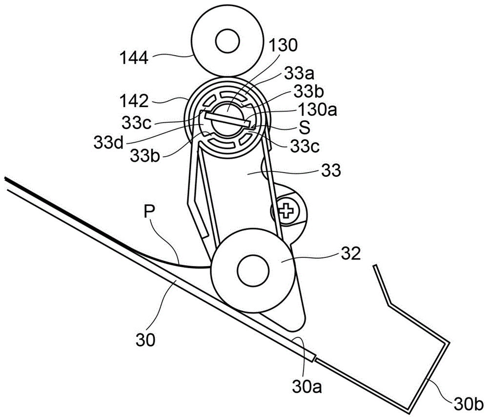
图4是表示本发明的一个实施方式的纸后处理装置的整合辊周边的构造的断面图,是表示辊支架配置在接触位置的状态的图。4 is a cross-sectional view showing a structure around an alignment roller of the paper post-processing device according to the embodiment of the present invention, and is a view showing a state where the roller support is arranged at a contact position.
图5是表示本发明的一个实施方式的纸后处理装置的遮光构件周边的构造的图,是表示在图4的状态中的遮光构件的旋转角度位置的图。5 is a diagram showing a structure around a light shielding member of the paper post-processing device according to the embodiment of the present invention, and is a view showing a rotational angle position of the light shielding member in the state of FIG. 4 .
图6是表示本发明的一个实施方式的纸后处理装置的整合辊以及传动齿轮周边的构造的图。FIG. 6 is a diagram showing a structure around an alignment roller and a transmission gear of the paper post-processing device according to the embodiment of the present invention.
图7是表示本发明的一个实施方式的纸后处理装置的整合辊周边的构造的断面图,是表示辊支架配置在退避位置的状态的图。7 is a cross-sectional view showing a structure around an alignment roller of the paper post-processing device according to the embodiment of the present invention, and is a view showing a state in which the roller support is arranged at a retracted position.
图8是表示本发明的一个实施方式的纸后处理装置的遮光构件周边的构造的图,是表示在图7的状态中的遮光构件的旋转角度位置的图。8 is a diagram showing a structure around a light shielding member of the paper post-processing apparatus according to an embodiment of the present invention, and is a view showing a rotational angle position of the light shielding member in the state of FIG. 7 .
图9是表示本发明的一个实施方式的纸后处理装置的整合辊周边的构造的断面图,是表示整合辊接触处理盘上最上面的纸的上表面的状态的图。9 is a cross-sectional view showing a structure around a aligning roller of the paper post-processing device according to one embodiment of the present invention, showing a state in which the aligning roller is in contact with the upper surface of the uppermost sheet on the processing tray.
图10是表示本发明的变形例的纸后处理装置的整合辊周边的构造的断面图。FIG. 10 is a cross-sectional view showing the structure around the alignment roller of the paper post-processing apparatus according to a modification of the present invention.
具体实施方式Detailed ways
以下,参照附图对本发明的实施方式进行说明。Hereinafter, embodiments of the present invention will be described with reference to the accompanying drawings.
首先,参照图1,对由图像形成装置100以及本发明的一个实施方式的纸后处理装置20构成的图像形成系统进行说明。此外,在本实施方式中作为图像形成装置100的一个例子举例说明了数码复合机,但是本发明的纸后处理装置20也同样可以与数码复合机以外的例如激光打印机或喷墨打印机、传真机等连接。First, with reference to FIG. 1 , an image forming system including an
如图1所示,图像形成装置100是所谓的体内排纸型的数码复合机,在图像形成装置100主体的上部设有将原稿的图像读取为电信号的图像读取部8,在其上设置了原稿输送装置3。在图像形成装置100主体的左侧部设置了纸后处理装置(薄片体后处理装置)20。As shown in FIG. 1 , the
在图像形成装置100主体上设有纸(薄片体)P的供纸部4、纸输送通道5、在纸P上形成调色剂图像的图像形成部6、用于定影纸P上的调色剂图像的定影装置7以及用于输送定影后的纸P并从图像形成装置100主体排出的纸排出部18。The main body of the
此外,在图像形成装置100主体上,朝向左侧面以及正面形成了大且敞开的体内排纸空间16,在该体内排纸空间16中,可以接受并叠放通过纸排出部18排出的纸P,并且设有在对纸P进行规定的后处理的情况下能够向纸后处理装置20输送的中继单元19。In addition, in the main body of the
纸排出部18具有上排出辊对18a以及配置在上排出辊对18a正下方的下排出辊对18b,纸输送通道5输送的纸P通过切换爪17被导向上方的输送通道或者下方的输送通道。The
通过切换爪17导向上方的输送通道的纸P从上排出辊对18a向左排出,通过切换爪17导向下方的输送通道的纸P通过下排出辊对18b向左排出。接着,从下排出辊对18b排出的纸P被送入中继单元19。被送入中继单元19内的纸P通过中继单元19内并被送入纸后处理装置20。切换爪17由主体控制部80可以切换引导方向。此外,主体控制部80控制图像形成装置100的动作并且能够与纸后处理装置20的后处理控制部81之间进行通信并控制后处理控制部81。后处理控制部81是本发明的“控制部”的一个例子。The paper P guided to the upper conveyance path by the switching
在纸后处理装置20内部具备:冲孔形成装置21,对被送入的纸P进行冲孔;处理盘30,多张叠放(堆叠)被送入的纸P;以及装订部(处理部)40,用订书钉装订在处理盘30上叠放的纸摞。在纸后处理装置20的侧面设有可升降到适合排出纸P的位置的排出盘50。在排出盘50上设有一对整合挡件55(参照图2),通过与叠放在排出盘50上的纸P的宽度方向的侧端缘抵接,将纸P在宽度方向上整合。Inside the
冲孔形成装置21配置在纸后处理装置20的上部,沿着与纸P的输送方向平行的一方的侧端缘(装置前侧或者后侧)形成多个冲孔。在冲孔形成装置21的上游侧且与纸输送方向垂直的方向(与图1的纸面垂直的方向)的大约中央部,配置了送入检测传感器(未图示),检测通过中继单元19内的纸送入辊对被送入纸后处理装置20内的纸P的前端。The
图2是表示本发明的一个实施方式的纸后处理装置20的处理盘30周边的构造的断面图。相对于纸输送方向在冲孔形成装置21(参照图1)的下游侧配置了中间辊对(输送构件)27。在中间辊对27的上游侧配置了检测纸P通过的传动型的纸检测传感器(未图示)。2 is a cross-sectional view showing a structure around a
而且,在中间辊对27的下方设置了:处理盘30,整合并叠放通过中间辊对27输送的规定张数的纸P;以及装订部40,对在处理盘30上叠放的纸P的摞(纸摞)进行装订处理(参照图1)。Further, below the
相对于纸排出方向在处理盘30的下游侧(图2的左侧)设置了纸排出口(薄片体排出口)22,在纸排出口22上配置了将纸P排出到排出盘50的排出辊对29。排出辊对29沿着纸宽度方向(与图2的纸面垂直的方向、与纸输送方向正交的方向)设有多个(在这里是2个)。此外,排出辊对29从驱动马达(未图示)通过排出齿轮28a以及传动带28b等传递旋转驱动力,由可正反旋转的橡胶制的下排出辊29a以及从动于下排出辊29a旋转的树脂制的上排出辊29b构成。A paper discharge port (sheet discharge port) 22 is provided on the downstream side (left side in FIG. 2 ) of the
上排出辊29b被以旋转轴31a为支点可上下摇动的排出辊支架31支撑,下排出辊29a以及上排出辊29b可相互接触或分离。排出辊支架31例如利用由步进马达以及齿轮或由马达、齿轮以及凸轮等构成的支架驱动机构36摇动。支架驱动机构36被后处理控制部81(参照图1)控制。The
上排出辊29b通过支架驱动机构36选择性地配置在与下排出辊29a接触并形成夹缝部的夹缝形成位置(图2的位置)或从上排出辊29b向上方离开的离开位置(未图示)。The
在处理盘30的上方且在中间辊对27的下游侧(图2的左侧),配置了敲击构件(未图示),用于将通过中间辊对27被送入的纸P向下方敲击并使其沿着处理盘30的纸放置面(薄片体放置面)30a。中间辊对27由利用驱动马达(未图示)可旋转的上辊27a以及从动于上辊27a旋转的下辊27b构成。在下辊27b的下方设置了以下辊27b的旋转轴(后述的旋转轴130)为支点可摇动的整合辊支架33以及由整合辊支架33支撑为可旋转且利用来自驱动马达(未图示)的旋转驱动力可旋转的整合辊(整合构件)32。整合辊32沿着纸宽度方向设有一对。此外,整合辊支架33是本发明的“支架”的一例。Above the
处理盘30朝向放置的纸P的后端(纸排出方向的上游端)侧(图2的右侧)向下倾斜着设置,整合辊32在以下辊27b的旋转轴为支点可向下方摇动的状态下,通过向图2的逆时针方向旋转,将纸P从上游端(后端)侧拉到处理盘30上,纸P的上游端与定位部30b抵接。由此,纸P在上游端对齐的状态下叠放在处理盘30上。此外,在处理盘30上设有一对侧端整合挡件(处理部)35,将在处理盘30上叠放的规定张数的纸摞在与纸输送方向正交的纸宽度方向上整合。The
此外,整合辊32由相对于纸P摩擦系数较小的树脂等材料形成,在纸P的后端抵接处理盘30的定位部30b之后整合辊32相对于纸P空转。对于整合辊32以及整合辊支架33周边的详细构造在后面叙述。The
装订部40(参照图1)通过移动机构(未图示)在纸宽度方向上能够移动,按照装订处理的内容,沿着处理盘30的下端部移动到规定位置。The binding unit 40 (see FIG. 1 ) is movable in the paper width direction by a moving mechanism (not shown), and moves to a predetermined position along the lower end of the
接着,参照图1对于纸后处理装置20的动作进行说明。当在图像形成装置100中进行了图像形成处理的纸P被送入时,在指示了形成冲孔的情况下,通过冲孔形成装置21在被输送的纸P的规定位置(例如沿着装置前侧的侧端缘的2个部位)上形成冲孔,在没有指示形成冲孔的情况下直接通过冲孔形成装置21。Next, the operation of the
接着,纸P通过中间辊对27(参照图2)进一步输送到下游侧。Next, the paper P is further conveyed to the downstream side by the intermediate roller pair 27 (refer to FIG. 2 ).
在没有指示进行在处理盘30上的后处理(利用装订部40的装订处理(装订处理)以及移位排出处理)的情况下,如图2所示,将通过了冲孔形成装置21的纸P利用中间辊对27以及排出辊对29直接排出到排出盘50。此时,排出辊支架31向下方摇动,将上排出辊29b配置到接触下排出辊29a的夹缝形成位置。When there is no instruction to perform post-processing on the processing tray 30 (binding processing (binding processing) by the binding
另一方面,在指示了进行在处理盘30上的后处理的情况下,在纸P的后端通过了中间辊对27的时刻,驱动敲击构件(未图示)使纸P沿着处理盘30。此时,排出辊支架31向上方摇动,将上排出辊29b配置到离开下排出辊29a的位置(离开位置)。在这种状态下,通过使整合辊32正转(向图2的逆时针方向旋转),纸P沿着处理盘30被拉入,并通过定位部30b整合后端。定位部30b不是在整个纸宽度方向上连续形成的,而是部分地形成切口。此时,纸P的前端与排出辊对29相比向下游侧突出。On the other hand, when the post-processing on the
接着,在指示了进行装订处理的情况下,当结束了接受1摞(规定张数)纸P时,使装订部40移动到定位部30b的切口位置并对纸摞的后端进行装订处理。装订处理之后,整合辊32配置到退避到上方的后述的退避位置。Next, when the stapling process is instructed, when receiving one bundle (predetermined number of sheets) of paper P is completed, the stapling
此外,在指示了进行移位排出处理的情况下,当结束了接受1摞(规定张数)纸P时,将侧端整合挡件35配置到整合了纸P的整合位置(基准位置)或者从整合位置在与排出方向正交的方向(纸宽度方向)上位移了规定量的位置(移位位置)。接着,使排出辊支架31摇动到下方来使上排出辊29b移动到与下排出辊29a抵接的位置(抵接位置)。之后,通过使下排出辊29a正转(图2的逆时针方向),将纸摞沿着处理盘30向纸排出方向下游侧输送并排出到排出盘50上。由此,纸摞交替排出到排出盘50上的基准排出位置以及从基准排出位置在与排出方向正交的方向(纸宽度方向)上位移了规定量的移位排出位置,当各纸摞排出到排出盘50上时在纸宽度方向上互不相同地叠放并区分开来。此外,在排出处理盘30上的纸摞的情况下,也可以通过支撑纸摞的上游端(后端)并且利用在处理盘30的纸放置面30a上沿排出方向移动的摞排出构件(未图示)排出纸摞。In addition, in the case where the shift discharge process is instructed, when the acceptance of one bundle (predetermined number of sheets) of paper P is completed, the side
接着,对整合辊32以及整合辊支架33周边的构造详细地进行说明。Next, the structures around the
如图3以及图4所示,整合辊32可旋转地设置在整合辊支架33的下端部。整合辊支架33设置为与旋转轴130(下辊27b(参照图2)的旋转轴)的旋转联动着摇动。下辊27b相对于旋转轴130可旋转地安装。As shown in FIGS. 3 and 4 , the
在旋转轴130上,如图3所示,在一对整合辊支架33的外侧上,可旋转地安装了将纸P的后端引导到处理盘30的定位部30b的导向构件132。此外,在旋转轴130的一个端部(图3的右端部)上,与旋转轴130一体固定有旋转的输入齿轮134以及遮光构件136。输入齿轮134通过连接齿轮138(参照图5)连接到步进马达(未图示)。在遮光构件136上一体设置了向径向外侧突出的扇形的遮光片136a。此外,输入齿轮134、连接齿轮138以及步进马达是本发明的“驱动部”的一个例子。On the
此外,在旋转轴130的一端部附近,如图5所示,设置了由具有发光部以及受光部的PI传感器构成的角度检测传感器(检测部)140。角度检测传感器140检测遮光构件136的遮光片136a敞开光路或者遮断光路,并将检测结果发送到后处理控制部81。此外,通过旋转轴130、角度检测传感器140、遮光构件136、输入齿轮134、连接齿轮138、步进马达(未图示)以及后述的卡合销130a等,构成了使整合辊支架33摇动的摇动机构150。Moreover, as shown in FIG. 5, the angle detection sensor (detection part) 140 which consists of a PI sensor which has a light-emitting part and a light-receiving part is provided in the vicinity of one end part of the
此外,如图3所示,在旋转轴130的规定位置上,相对于旋转轴130可旋转地安装了将旋转驱动力传递到整合辊32的传动齿轮142。如图6所示,传动齿轮142通过中间齿轮144(参照图6)连接到驱动马达(未图示)。在传动齿轮142上一体形成了轮142a,在整合辊32上一体形成了轮32a。传动带146卷挂在轮142a以及轮32a上,通过传动齿轮142旋转,整合辊32旋转。此外,当整合辊支架33至少配置在后述的退避位置以外的位置时,整合辊32沿着图4的逆时针方向旋转,在本实施方式中始终旋转。Further, as shown in FIG. 3 , at a predetermined position of the
整合辊支架33设计为从后述的轴插入部33a朝向前端向纸排出方向上游侧倾斜,整合辊32在纸放置面30a或者接触纸P的上表面的接触位置(图4或图9的位置)与整合辊32从纸放置面30a向上方退避的退避位置(图7的位置)之间可摇动。此外,整合辊支架33以纸排出方向的下游侧端部(后述的轴插入部33a)为中心可摇动,如后所述,通过与纸P的后端抵接在退避方向上稍稍摇动(反弹)。The aligning
此外,整合辊支架33当从接触位置(图4的位置)向朝向退避位置(图7的位置)的退避方向(图4的逆时针方向)摇动时通过摇动机构150摇动,当从退避位置向朝向接触位置的接触方向(图4的顺时针方向)摇动时通过重力的作用摇动。In addition, when the aligning
具体来说,整合辊支架33具有插入了旋转轴130的轴插入部33a。在旋转轴130上设置了向径向突出的卡合销130a。卡合销130a在径向上贯通旋转轴130。在轴插入部33a上设置了与卡合销130a卡合的卡合槽33d,在卡合槽33d上,抵接壁33b以及33c以隔着卡合销130a的状态在旋转方向上隔开规定间隔相对配置。即,整合辊支架33相对于旋转轴130在旋转方向上以规定的角度范围具有游隙的状态被支撑。Specifically, the integrating
当旋转轴130向图4的逆时针方向旋转时,卡合销130a与抵接壁33b抵接并且使整合辊支架33沿着退避方向(图4的逆时针方向)摇动。如图8所示,当遮光片136a遮住角度检测传感器140的光路并且角度检测传感器140检测到遮光片136a时,使旋转轴130的旋转停止,将整合辊支架33配置到退避位置(图7的位置)。此外,遮光片136a遮断角度检测传感器140的光路时的旋转角度位置是旋转轴130的起始位置。When the
旋转轴130与处理盘30上的纸P的张数对应,配置在规定的旋转角度位置。The
例如,在处理盘30上没有纸P的情况下,通过旋转轴130从起始位置向图7的顺时针方向旋转规定的旋转角度,卡合销130a向顺时针方向旋转,整合辊支架33由于重力的作用向接触方向(图7的顺时针方向)摇动并配置在接触位置(图4的位置)。在本实施方式中,如图3所示,在整合辊支架33上安装了砝码143,整合辊支架33通过作用在整合辊32、整合辊支架33以及砝码143上的重力向下方摇动。此外,砝码143是根据需要设置的东西,也可以不设置。For example, when there is no paper P on the
此外,当处理盘30上的纸P的张数增加时,旋转轴130仅向图4的逆时针方向旋转与处理盘30上的纸P的张数对应的角度,整合辊支架33向退避方向(图4的逆时针方向)摇动。In addition, when the number of sheets of paper P on the
此外,在整合辊32与处理盘30的纸放置面30a抵接的状态(图4的状态)下以及与处理盘30上的最上面的纸P的上表面抵接的状态(图9的状态)下,卡合销130a相对于抵接壁33b以及抵接壁33c具有规定的间隙地配置。抵接壁33c限制整合辊支架33向退避方向的摇动,整合辊支架33向退避方向仅能够以与抵接壁33c和卡合销130a之间的间隙对应的角度摇动。In addition, in the state where the
后处理控制部81(参照图1)由CPU(Central Processing Unit)、ROM(Read OnlyMemory)以及RAM(Random Access Memory)等构成,总体控制纸后处理装置20。此外,后处理控制部81通过设置在后处理装置20的接收部(取得部)82(参照图1)接收用户输入到图像形成装置100的操作部(未图示)的与纸摞的厚度相关的信息(纸P的种类(纸P的材质或厚度)、1摞纸P的张数等)。此外,后处理控制部81基于来自纸检测传感器(未图示)的检测信号,对处理盘30上的纸P的张数进行计数。The post-processing control unit 81 (see FIG. 1 ) includes a CPU (Central Processing Unit), a ROM (Read Only Memory), a RAM (Random Access Memory), and the like, and controls the
后处理控制部81至少基于处理盘30上纸P的张数变更旋转轴130的旋转角度位置。其中,后处理控制部81基于处理盘30上的纸摞的厚度(纸P的总厚度)、即与处理盘30上的纸P的张数和每一张纸P的厚度相关的信息,设定接触位置与退避位置之间的旋转轴130的旋转角度位置。The post-processing control unit 81 changes the rotational angle position of the
其中,当整合处理盘30上的纸P的后端时,有通过中间辊对27被敲击构件(未图示)敲落的纸P的后端如图4所示与整合辊32或整合辊支架33抵接的情况。在这种情况下,整合辊支架33向退避方向摇动(被推上去),当纸P的后端通过整合辊支架33的下方时,整合辊支架33回到下方的位置。此时,在处理盘30上的纸P的张数较少的情况下,由于整合辊支架33因纸P摇动的量(摇动角度)较大,所以当整合辊支架33回到下方的位置时整合辊32与纸P的上表面强力地抵接。由此,因为施加到纸P的输送力增大,所以纸P的后端部(整合辊32与定位部30b之间的部分)弯曲,发生整合不良。Among them, when the rear end of the paper P on the
因此,在本实施方式中,在整合辊32接触纸放置面30a或者纸P的上表面的状态下,处理盘30上的纸P的张数较少的情况下(例如图4的情况),与纸P的张数较多的情况下(例如图9的情况)相比,后处理控制部81使旋转轴130配置在规定的旋转角度位置,以使整合辊支架33向退避方向的游隙变小。Therefore, in the present embodiment, when the number of sheets of paper P on the
具体来说,如图4所示,在处理盘30上的纸P的张数较少的情况下,旋转轴130配置为卡合销130a与抵接壁33c的间隙(整合辊支架33向退避方向的游隙)S例如为1mm以下。因此,即使在纸P的后端与整合辊32或整合辊支架33抵接的情况下,整合辊支架33仅能向逆时针方向稍稍摇动(不被推上去)。因此,可以抑制当纸P的后端通过整合辊支架33的下方、整合辊支架33回到下方时整合辊32对纸P的上表面强力地抵接。Specifically, as shown in FIG. 4 , when the number of sheets of paper P on the
另一方面,在处理盘30上的纸P的张数较多的情况下(例如图9的情况),旋转轴130配置为卡合销130a与抵接壁33c的间隙S例如是2mm左右。在处理盘30上的纸P的张数较多的情况下(例如图9的情况),与处理盘30上的纸P的张数较少的情况下(例如图4的情况)相比,由于整合辊支架33相对于处理盘30的纸放置面30a处于接近平行的状态,整合辊支架33因纸P摇动的量(摇动角度)较小。因此,当纸P的后端通过整合辊支架33的下方并且整合辊支架33回到下方时,整合辊32对纸P的上表面不会强力地抵接,所以很难发生整合不良。On the other hand, when the number of sheets of paper P on the
此外,间隙S的间隔是卡合销130a的规定的位置与抵接壁33c的距离。间隙S的大小也可以代替卡合销130a的规定的位置与抵接壁33c的距离,而由卡合销130a与抵接壁33c所成的角度定义。In addition, the space|interval of the clearance gap S is the distance of the predetermined position of the
另外,随着处理盘30上的纸P的张数增多(例如纸P每增加10~20张左右),后处理控制部81以卡合销130a与抵接壁33c的间隙(整合辊支架33向退避方向的游隙)S逐渐增大的方式逐渐旋转旋转轴130。In addition, as the number of sheets of paper P on the
在本实施方式中,如上所述,在整合辊32与纸放置面30a或者纸P的上表面接触的状态下,处理盘30上的纸P的张数较少的情况下与纸P的张数较多的情况相比,后处理控制部81以整合辊支架33向退避方向的游隙变小的方式使旋转轴130配置在规定的旋转角度位置。由此,在处理盘30上的纸P的张数较少的情况下,当后续的纸P的后端与整合辊32或者整合辊支架33抵接并且将整合辊支架33推上去时可以减小摇动角度。因此,当后续的纸P的后端通过整合辊支架33的下方并且整合辊支架33向接触位置返回时,可以抑制整合辊32对纸P的上表面强力地抵接。因此,可以抑制施加到纸P的输送力增大导致纸P的后端部(整合辊32与定位部30b之间的部分)弯曲,从而可以抑制发生整合不良。In this embodiment, as described above, in the state where the
此外,在处理盘30上的纸P的张数较多的情况下,由于纸摞的弹性变强,因此有因纸摞的弯曲等导致整合辊32对纸P过度按压的情况。在本实施方式中,处理盘30上的纸P的张数较多的情况与纸P的张数较少的情况相比,整合辊支架33向退避方向的游隙变大,所以可以抑制整合辊32对纸P过度按压。In addition, when the number of sheets of paper P on the
此外,如上所述,随着处理盘30上的纸P的张数增多,后处理控制部81以整合辊支架33向退避方向的游隙逐渐增大的方式使旋转轴130旋转。由此,可以与处理盘30上的纸P的张数对应,将整合辊支架33向退避方向的游隙设定为合适的大小。Further, as described above, as the number of sheets of paper P on the
此外,如上所述,在整合辊支架33的轴插入部33a上设有抵接壁33c,在整合辊32与处理盘30上的最上面的纸P的上表面抵接的状态下,相对于卡合销130a具有间隙S地配置并且限制整合辊支架33向退避方向的摇动。由此,可以容易地限制后续的纸P的后端使整合辊支架33摇动的量(摇动角度)。In addition, as described above, the
此外,如上所述,摇动机构150具有与旋转轴130一起旋转的遮光构件136以及检测遮光构件136使光路敞开或者遮断的角度检测传感器140,后处理控制部81基于角度检测传感器140的检测结果使旋转轴130旋转。由此,可以将旋转轴130容易地配置在规定的旋转角度位置。Further, as described above, the
此外,如上所述,后处理控制部81基于接收部82取得的信息将旋转轴130配置在规定的旋转角度位置。由此,可以容易地将整合辊支架33向退避方向的游隙设定为合适的大小。Further, as described above, the post-processing control unit 81 arranges the
另外,本发明的实施方式仅为示例而不是限制性的。本发明的范围不是上述说明的实施方式而是由权利要求来表示,且还包括与权利要求等同的内容以及在权利要求范围内所有的变更。In addition, the embodiments of the present invention are merely illustrative and not restrictive. The scope of the present invention is indicated not by the above-described embodiments but by the claims, and includes equivalents to the claims and all modifications within the scope of the claims.
例如,在上述实施方式中,例举了通过整合辊32将纸P拉入与中间辊对27的输送方向相反的方向(图2的右方)的例子,即,整合纸P的后端的例子,但是本发明不限于此。例如图10所示的本发明的变形例的纸后处理装置20那样,也可以通过整合辊32将纸P拉入与中间辊对27的输送方向相同的方向(图10的左方)。即,通过整合辊32整合纸P的前端。For example, in the above-described embodiment, an example in which the paper P is pulled in the direction opposite to the conveying direction of the intermediate roller pair 27 (right side in FIG. 2 ) by the aligning
此外,在上述实施方式中,作为整合构件使用辊(整合辊)进行了示例,但是本发明不限于此,也可以使用叶片或带等作为整合构件。In addition, in the said embodiment, although the roller (alignment roller) was used as an example as an alignment member, this invention is not limited to this, A blade, a belt, etc. may be used as an alignment member.
Claims (9)
Applications Claiming Priority (2)
| Application Number | Priority Date | Filing Date | Title |
|---|---|---|---|
| JP2018-161569 | 2018-08-30 | ||
| JP2018161569A JP7087837B2 (en) | 2018-08-30 | 2018-08-30 | Sheet post-processing device and image forming system equipped with it |
Publications (2)
| Publication Number | Publication Date |
|---|---|
| CN110872019A true CN110872019A (en) | 2020-03-10 |
| CN110872019B CN110872019B (en) | 2021-07-20 |
Family
ID=69640816
Family Applications (1)
| Application Number | Title | Priority Date | Filing Date |
|---|---|---|---|
| CN201910783508.6A Expired - Fee Related CN110872019B (en) | 2018-08-30 | 2019-08-23 | Sheet post-processing device and image forming system including the same |
Country Status (3)
| Country | Link |
|---|---|
| US (1) | US10941013B2 (en) |
| JP (1) | JP7087837B2 (en) |
| CN (1) | CN110872019B (en) |
Cited By (1)
| Publication number | Priority date | Publication date | Assignee | Title |
|---|---|---|---|---|
| CN115385162A (en) * | 2021-05-21 | 2022-11-25 | 富士胶片商业创新有限公司 | Post-processing apparatus and image forming apparatus |
Families Citing this family (3)
| Publication number | Priority date | Publication date | Assignee | Title |
|---|---|---|---|---|
| US11299364B2 (en) * | 2018-05-15 | 2022-04-12 | Hewlett-Packard Development Company, L.P. | Paddle roller rotations |
| JP2024097187A (en) | 2023-01-05 | 2024-07-18 | 京セラドキュメントソリューションズ株式会社 | SHEET POST-TREATING DEVICE AND IMAGE FORMING SYSTEM INCLUDING THE SAME |
| JP2024156573A (en) | 2023-04-24 | 2024-11-06 | 京セラドキュメントソリューションズ株式会社 | Post-processing device and image forming apparatus |
Citations (4)
| Publication number | Priority date | Publication date | Assignee | Title |
|---|---|---|---|---|
| CN1754810A (en) * | 2004-09-29 | 2006-04-05 | 东芝泰格有限公司 | Paper post-processing device |
| US20080317534A1 (en) * | 2007-06-19 | 2008-12-25 | Kabushiki Kaisha Toshiba | Sheet processing apparatus |
| US20110049790A1 (en) * | 2009-08-31 | 2011-03-03 | Nisca Corporation | Sheet collecting apparatus and image formation system provided with the apparatus |
| CN102963758A (en) * | 2011-08-29 | 2013-03-13 | 株式会社东芝 | Sheet processing apparatus and sheet conveying method |
Family Cites Families (11)
| Publication number | Priority date | Publication date | Assignee | Title |
|---|---|---|---|---|
| US5288062A (en) * | 1992-05-26 | 1994-02-22 | Xerox Corporation | High capacity compiler with vertically adjustable sheet discharge and acquire means |
| US7396008B2 (en) * | 2004-07-22 | 2008-07-08 | Fuji Xerox Co., Ltd. | Stapling device |
| JP4920883B2 (en) * | 2004-11-05 | 2012-04-18 | キヤノン株式会社 | Sheet processing apparatus and image forming apparatus |
| JP4891005B2 (en) * | 2006-09-04 | 2012-03-07 | ニスカ株式会社 | Sheet alignment apparatus, post-processing apparatus including the same, and image forming apparatus |
| JP4806612B2 (en) * | 2006-09-22 | 2011-11-02 | ニスカ株式会社 | Sheet alignment apparatus, post-processing apparatus including the same, and image forming apparatus |
| JP2009292639A (en) | 2008-06-09 | 2009-12-17 | Canon Finetech Inc | Sheet post-processing device, and image forming device having the same |
| JP2010083607A (en) | 2008-09-30 | 2010-04-15 | Sharp Corp | Postprocessing device |
| JP5479420B2 (en) * | 2011-08-29 | 2014-04-23 | シャープ株式会社 | Post-processing device and paper processing device |
| JP5963043B2 (en) | 2012-04-24 | 2016-08-03 | 株式会社リコー | Paper processing apparatus and image forming apparatus |
| JP2013252909A (en) | 2012-06-05 | 2013-12-19 | Canon Finetech Inc | Sheet processing device and image forming apparatus |
| JP6335451B2 (en) * | 2013-08-06 | 2018-05-30 | キヤノン株式会社 | Sheet processing apparatus and image forming apparatus |
-
2018
- 2018-08-30 JP JP2018161569A patent/JP7087837B2/en active Active
-
2019
- 2019-08-23 US US16/549,805 patent/US10941013B2/en not_active Expired - Fee Related
- 2019-08-23 CN CN201910783508.6A patent/CN110872019B/en not_active Expired - Fee Related
Patent Citations (4)
| Publication number | Priority date | Publication date | Assignee | Title |
|---|---|---|---|---|
| CN1754810A (en) * | 2004-09-29 | 2006-04-05 | 东芝泰格有限公司 | Paper post-processing device |
| US20080317534A1 (en) * | 2007-06-19 | 2008-12-25 | Kabushiki Kaisha Toshiba | Sheet processing apparatus |
| US20110049790A1 (en) * | 2009-08-31 | 2011-03-03 | Nisca Corporation | Sheet collecting apparatus and image formation system provided with the apparatus |
| CN102963758A (en) * | 2011-08-29 | 2013-03-13 | 株式会社东芝 | Sheet processing apparatus and sheet conveying method |
Cited By (1)
| Publication number | Priority date | Publication date | Assignee | Title |
|---|---|---|---|---|
| CN115385162A (en) * | 2021-05-21 | 2022-11-25 | 富士胶片商业创新有限公司 | Post-processing apparatus and image forming apparatus |
Also Published As
| Publication number | Publication date |
|---|---|
| US20200071116A1 (en) | 2020-03-05 |
| US10941013B2 (en) | 2021-03-09 |
| JP7087837B2 (en) | 2022-06-21 |
| CN110872019B (en) | 2021-07-20 |
| JP2020033156A (en) | 2020-03-05 |
Similar Documents
| Publication | Publication Date | Title |
|---|---|---|
| JP4047092B2 (en) | Sheet post-processing apparatus and image forming apparatus including the apparatus | |
| JP4095341B2 (en) | Sheet stacking alignment apparatus, sheet processing apparatus, and image forming apparatus | |
| US7630681B2 (en) | Sheet processing apparatus and image forming apparatus | |
| JP4047091B2 (en) | Sheet post-processing apparatus and image forming apparatus including the apparatus | |
| US8042796B2 (en) | Sheet finishing apparatus, sheet punching apparatus and control method | |
| CN110872019B (en) | Sheet post-processing device and image forming system including the same | |
| US7883079B2 (en) | Sheet processing apparatus | |
| US6886828B2 (en) | Sheet finishing apparatus and image forming apparatus equipped with the same | |
| JP2009292639A (en) | Sheet post-processing device, and image forming device having the same | |
| US7173717B2 (en) | Sheet post-processing apparatus and image forming apparatus equipped with the same | |
| US6695300B2 (en) | Sheet finishing apparatus and image forming apparatus equipped with the same | |
| US6951334B2 (en) | Sheet post-processing apparatus and image forming apparatus equipped with the same | |
| JP5389514B2 (en) | Sheet conveying apparatus, image forming apparatus, and image forming system | |
| JP2019006561A (en) | Sheet post-processing apparatus and image forming system having the same | |
| JP2002160848A (en) | Paper handling equipment | |
| JP7780283B2 (en) | Sheet processing apparatus and image forming apparatus | |
| JP4154278B2 (en) | Sheet processing apparatus and image forming apparatus | |
| JP6021413B2 (en) | Sheet stacking apparatus and image forming apparatus | |
| JP5336316B2 (en) | Sheet stacking apparatus, post-processing apparatus including the same, and image forming system | |
| JP4081076B2 (en) | Sheet post-processing device | |
| JP3857008B2 (en) | Paper loading device | |
| JP4593516B2 (en) | Paper loading device | |
| JP2025053932A (en) | Sheet stacking device and image forming system | |
| JP2007314322A (en) | Sheet conveying apparatus, sheet processing apparatus, and image forming apparatus | |
| JP2020083506A (en) | Sheet discharging device, sheet post-processing device including the same, and image forming system |
Legal Events
| Date | Code | Title | Description |
|---|---|---|---|
| PB01 | Publication | ||
| PB01 | Publication | ||
| SE01 | Entry into force of request for substantive examination | ||
| SE01 | Entry into force of request for substantive examination | ||
| GR01 | Patent grant | ||
| GR01 | Patent grant | ||
| CF01 | Termination of patent right due to non-payment of annual fee |
Granted publication date: 20210720 |
|
| CF01 | Termination of patent right due to non-payment of annual fee |