CN110873680A - Particle Detection Module - Google Patents
Particle Detection Module Download PDFInfo
- Publication number
- CN110873680A CN110873680A CN201811001754.3A CN201811001754A CN110873680A CN 110873680 A CN110873680 A CN 110873680A CN 201811001754 A CN201811001754 A CN 201811001754A CN 110873680 A CN110873680 A CN 110873680A
- Authority
- CN
- China
- Prior art keywords
- detection
- particle
- channel
- detection module
- base
- Prior art date
- Legal status (The legal status is an assumption and is not a legal conclusion. Google has not performed a legal analysis and makes no representation as to the accuracy of the status listed.)
- Granted
Links
- 238000001514 detection method Methods 0.000 title claims abstract description 131
- 239000002245 particle Substances 0.000 title claims abstract description 97
- 239000000725 suspension Substances 0.000 claims description 41
- 238000000034 method Methods 0.000 claims description 6
- 230000000694 effects Effects 0.000 claims description 4
- 238000004891 communication Methods 0.000 claims description 2
- 238000005530 etching Methods 0.000 claims description 2
- 239000011521 glass Substances 0.000 claims description 2
- 230000002093 peripheral effect Effects 0.000 claims description 2
- 238000005452 bending Methods 0.000 claims 2
- NJPPVKZQTLUDBO-UHFFFAOYSA-N novaluron Chemical compound C1=C(Cl)C(OC(F)(F)C(OC(F)(F)F)F)=CC=C1NC(=O)NC(=O)C1=C(F)C=CC=C1F NJPPVKZQTLUDBO-UHFFFAOYSA-N 0.000 abstract 1
- 238000010586 diagram Methods 0.000 description 6
- 238000013461 design Methods 0.000 description 5
- 230000008901 benefit Effects 0.000 description 4
- 239000000463 material Substances 0.000 description 4
- 239000000853 adhesive Substances 0.000 description 3
- 230000001070 adhesive effect Effects 0.000 description 3
- 230000005540 biological transmission Effects 0.000 description 3
- 239000000443 aerosol Substances 0.000 description 2
- 239000003292 glue Substances 0.000 description 2
- 238000007731 hot pressing Methods 0.000 description 2
- 210000004072 lung Anatomy 0.000 description 2
- 238000012544 monitoring process Methods 0.000 description 2
- 208000024172 Cardiovascular disease Diseases 0.000 description 1
- 206010061218 Inflammation Diseases 0.000 description 1
- 238000003915 air pollution Methods 0.000 description 1
- 208000006673 asthma Diseases 0.000 description 1
- 239000011248 coating agent Substances 0.000 description 1
- 238000000576 coating method Methods 0.000 description 1
- 230000006835 compression Effects 0.000 description 1
- 238000007906 compression Methods 0.000 description 1
- 230000008602 contraction Effects 0.000 description 1
- 238000001816 cooling Methods 0.000 description 1
- 238000000354 decomposition reaction Methods 0.000 description 1
- 230000005611 electricity Effects 0.000 description 1
- 238000005516 engineering process Methods 0.000 description 1
- 239000003344 environmental pollutant Substances 0.000 description 1
- 239000010419 fine particle Substances 0.000 description 1
- 230000004054 inflammatory process Effects 0.000 description 1
- 238000003475 lamination Methods 0.000 description 1
- 238000000465 moulding Methods 0.000 description 1
- 210000003928 nasal cavity Anatomy 0.000 description 1
- 231100000719 pollutant Toxicity 0.000 description 1
- 238000012545 processing Methods 0.000 description 1
- 230000000750 progressive effect Effects 0.000 description 1
- 238000004080 punching Methods 0.000 description 1
- 210000002345 respiratory system Anatomy 0.000 description 1
- 238000004904 shortening Methods 0.000 description 1
- 239000007787 solid Substances 0.000 description 1
- 210000003135 vibrissae Anatomy 0.000 description 1
Images





Classifications
-
- G—PHYSICS
- G01—MEASURING; TESTING
- G01N—INVESTIGATING OR ANALYSING MATERIALS BY DETERMINING THEIR CHEMICAL OR PHYSICAL PROPERTIES
- G01N15/00—Investigating characteristics of particles; Investigating permeability, pore-volume or surface-area of porous materials
- G01N15/02—Investigating particle size or size distribution
- G01N15/0205—Investigating particle size or size distribution by optical means
-
- G—PHYSICS
- G01—MEASURING; TESTING
- G01N—INVESTIGATING OR ANALYSING MATERIALS BY DETERMINING THEIR CHEMICAL OR PHYSICAL PROPERTIES
- G01N15/00—Investigating characteristics of particles; Investigating permeability, pore-volume or surface-area of porous materials
- G01N15/06—Investigating concentration of particle suspensions
-
- G—PHYSICS
- G01—MEASURING; TESTING
- G01N—INVESTIGATING OR ANALYSING MATERIALS BY DETERMINING THEIR CHEMICAL OR PHYSICAL PROPERTIES
- G01N15/00—Investigating characteristics of particles; Investigating permeability, pore-volume or surface-area of porous materials
- G01N15/06—Investigating concentration of particle suspensions
- G01N15/075—Investigating concentration of particle suspensions by optical means
-
- Y—GENERAL TAGGING OF NEW TECHNOLOGICAL DEVELOPMENTS; GENERAL TAGGING OF CROSS-SECTIONAL TECHNOLOGIES SPANNING OVER SEVERAL SECTIONS OF THE IPC; TECHNICAL SUBJECTS COVERED BY FORMER USPC CROSS-REFERENCE ART COLLECTIONS [XRACs] AND DIGESTS
- Y02—TECHNOLOGIES OR APPLICATIONS FOR MITIGATION OR ADAPTATION AGAINST CLIMATE CHANGE
- Y02A—TECHNOLOGIES FOR ADAPTATION TO CLIMATE CHANGE
- Y02A50/00—TECHNOLOGIES FOR ADAPTATION TO CLIMATE CHANGE in human health protection, e.g. against extreme weather
- Y02A50/20—Air quality improvement or preservation, e.g. vehicle emission control or emission reduction by using catalytic converters
Landscapes
- Chemical & Material Sciences (AREA)
- Dispersion Chemistry (AREA)
- Physics & Mathematics (AREA)
- Health & Medical Sciences (AREA)
- Life Sciences & Earth Sciences (AREA)
- Analytical Chemistry (AREA)
- Biochemistry (AREA)
- General Health & Medical Sciences (AREA)
- General Physics & Mathematics (AREA)
- Immunology (AREA)
- Pathology (AREA)
- Investigating Or Analysing Materials By Optical Means (AREA)
Abstract
Description
【技术领域】【Technical field】
本案关于一种微粒检测模块,尤指一种可组配于薄型可携式装置进行气体监测的微粒检测模块。This case is about a particle detection module, especially a particle detection module that can be assembled in a thin portable device for gas monitoring.
【背景技术】【Background technique】
悬浮微粒是指于空气中含有的固体颗粒或液滴,由于其粒径非常细微,容易通过鼻腔内的鼻毛进入人体的肺部,因而引起肺部的发炎、气喘或心血管的病变,若是其他污染物依附于悬浮微粒上,更会加重对于呼吸系统的危害。近年来,空气污染问题渐趋严重,尤其是细悬浮微粒(例如:PM2.5或PM10)的浓度数据常常过高,空气悬浮微粒浓度的监测渐受重视,但由于空气会随风向、风量不定量的流动,而目前检测悬浮微粒的空气品质监测站大都为定点,所以根本无法确认当下周遭的悬浮微粒浓度,因此需要一个微型方便携带的气体检测装置来供使用者可无时无刻、随时随地的检测周遭的悬浮微粒浓度。Suspended particulates refer to solid particles or droplets contained in the air. Because of their very fine particle size, they can easily enter the lungs of the human body through the nose hairs in the nasal cavity, thereby causing inflammation of the lungs, asthma or cardiovascular diseases. Pollutants attach to suspended particles, which will aggravate the harm to the respiratory system. In recent years, the problem of air pollution has become more and more serious, especially the concentration data of fine suspended particles (for example: PM2.5 or PM10) are often too high. Unquantified flow, and the current air quality monitoring stations for detecting suspended particulates are mostly fixed-point, so it is impossible to confirm the concentration of suspended particulates in the immediate surroundings. Therefore, a miniature and portable gas detection device is needed for users to be able to use it anytime, anywhere. Check the surrounding aerosol concentration.
有鉴于此,要如何能够随时随地监测悬浮微粒的浓度,实为目前迫切需要解决的问题。In view of this, how to monitor the concentration of suspended particulates anytime and anywhere is a problem that needs to be solved urgently.
【发明内容】[Content of the invention]
本案的主要目的是提供一种微粒检测模块,利用薄型基座的检测通道及光束通道,配置定位检测部件的激光器及微粒传感器在其中,以检测通过检测通道与光束通道正交位置的气体中所含悬浮微粒大小及浓度,并利用微型泵将基座外气体快速汲取进入检测通道去检测气体中悬浮微粒的浓度,使应用组装于可携式电子装置及穿戴配件上,以形成移动式微粒检测模块,供使用者可无时无刻、随时随地的监测周遭的悬浮微粒浓度。The main purpose of this case is to provide a particle detection module, which utilizes the detection channel and beam channel of a thin base, and configures a laser and a particle sensor for positioning the detection component in it, so as to detect all particles in the gas passing through the detection channel and the beam channel at an orthogonal position. Contains the size and concentration of suspended particles, and uses a micro pump to quickly draw the gas outside the base into the detection channel to detect the concentration of suspended particles in the gas, so that the application can be assembled on portable electronic devices and wearable accessories to form a mobile particle detection The module allows users to monitor the surrounding aerosol concentration anytime, anywhere.
本案的一广义实施态样为一种微粒检测模块,包含:一基座,内部具有一检测部件承载区、一微型泵承载区、一检测通道及一光束通道,该微型泵承载区具有一导气凹槽,该微型泵承载区与该检测通道连通,该检测部件承载区与该光束通道连通,且该检测通道与该光束通道为正交设置;一检测部件,包含一激光器及一微粒传感器,该激光器设置于该基座的该检测部件承载区定位,并能发射光束投射于该光束通道中,该微粒传感器对应设置到该检测通道与该光束通道正交位置;一微型泵,承载于该基座的该微型泵承载区中,并封盖该导气凹槽;其中该微型泵受驱动吸附引导该基座外部的气体快速导入该检测通道中,该气体通过该检测通道与该光束通道正交位置,受该激光器照射而投射光点至该微粒传感器,该微粒传感器检测气体中所含悬浮微粒大小及浓度。A broad implementation aspect of the present case is a particle detection module, comprising: a base with a detection component bearing area, a micro-pump bearing area, a detection channel and a beam channel inside, and the micro-pump bearing area has a guide an air groove, the micro-pump bearing area is communicated with the detection channel, the detection component bearing area is communicated with the beam channel, and the detection channel and the beam channel are arranged orthogonally; a detection component includes a laser and a particle sensor , the laser is positioned in the bearing area of the detection component of the base, and can emit a beam to project in the beam channel, and the particle sensor is correspondingly set to the orthogonal position of the detection channel and the beam channel; a micro pump is carried on the In the micro-pump bearing area of the base, and cover the air-guiding groove; wherein the micro-pump is driven to adsorb and guide the gas outside the base to quickly introduce into the detection channel, and the gas passes through the detection channel and the beam. The orthogonal position of the channel is irradiated by the laser to project a light spot to the particle sensor, and the particle sensor detects the size and concentration of suspended particles contained in the gas.
【附图说明】【Description of drawings】
图1所示为本案微粒检测模块的外观示意图。FIG. 1 is a schematic diagram of the appearance of the particle detection module of the present invention.
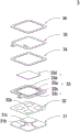
图2所示为本案微粒检测模块的相关构件分解示意图。Figure 2 shows a schematic diagram of the decomposition of the relevant components of the particle detection module of the present invention.
图3所示为本案微粒检测模块的基座示意图。FIG. 3 is a schematic diagram of the base of the particle detection module of the present invention.
图4所示为本案微粒检测模块的检测实施示意图。FIG. 4 shows a schematic diagram of the detection implementation of the particle detection module of the present invention.
图5A所示为本案微粒检测模块的微型泵相关构件由俯视角度视得的分解示意图。FIG. 5A shows an exploded schematic view of the micro-pump-related components of the particle detection module of the present invention from a top view.
图5B所示为本案微粒检测模块的微型泵相关构件由仰视角度视得的分解示意图。FIG. 5B shows an exploded schematic view of the micro-pump-related components of the particle detection module of the present invention viewed from a bottom-up angle.
图6A所示为本案微粒检测模块的微型泵的剖面示意图。FIG. 6A is a schematic cross-sectional view of the micropump of the particle detection module of the present invention.
图6B所示为本案微粒检测模块的微型泵另一压电致动器实施例的剖面示意图。FIG. 6B is a schematic cross-sectional view of another embodiment of the piezoelectric actuator of the micropump of the particle detection module of the present invention.
图6C至图6E所示为图6A中本案微粒检测模块的微型泵作动示意图。FIG. 6C to FIG. 6E are schematic diagrams illustrating the operation of the micro-pump of the particle detection module of the present application in FIG. 6A .
图7所示为本案微粒检测模块的基座外盖板件的外观示观图。FIG. 7 is a view showing the appearance of the outer cover plate of the base of the particle detection module of the present invention.
【具体实施方式】【Detailed ways】
体现本案特征与优点的一些典型实施例将在后段的说明中详细叙述。应理解的是本案能够在不同的态样上具有各种的变化,其皆不脱离本案的范围,且其中的说明及图示在本质上当作说明之用,而非用以限制本案。Some typical embodiments embodying the features and advantages of the present case will be described in detail in the description of the latter paragraph. It should be understood that this case can have various changes in different aspects, all of which do not depart from the scope of this case, and the descriptions and diagrams therein are essentially used for illustration rather than limiting this case.
请参阅图1至图4所示,本案提供一种微粒检测模块,包含一基座1、一检测部件2、一微型泵3。本案所提供微粒检测模块为了能组装应用于可携式电子装置及穿戴配件上,其中基座1具有一长度L、一宽度W及一高度H之外观尺寸,为了与检测部件2及微型泵3组配,依目前最佳化配置且符合薄型微小化的设计,将基座1的长度L配置为10~60mm,长度L为34~36mm为最佳,宽度W配置为10~50mm,宽度W为29~31mm为最佳,以及高度H配置为1~7mm,高度H为4.5~5.5mm为最佳,让整个微粒检测模块具备携带便利性的实施设计。Please refer to FIG. 1 to FIG. 4 , the present application provides a particle detection module, which includes a
请参阅图1至图4所示,上述的基座1具有一第一表面1a及一第二表面1b,第一表面1a及第二表面1b为相对设置的两个表面,基座1内部具有一检测部件承载区11、一微型泵承载区12、一检测通道13及一光束通道14,其中微型泵承载区12设置于第一表面1a,并具有一导气凹槽121,而检测部件承载区11、检测通道13及光束通道14分别贯通第一表面1a及第二表面1b,且微型泵承载区12与检测通道13连通,检测部件承载区11与光束通道14连通,且检测通道13与光束通道14为正交设置,又基座1侧边上具有一进气入口15及一排气出口16,进气入口15与检测通道13连通,排气出口16与导气凹槽121连通。Please refer to FIG. 1 to FIG. 4 , the above-mentioned
请参阅图2所示,上述检测部件2包含有一检测驱动电路板21、一微粒传感器22、一激光器23及一微处理器24。其中微粒传感器22、激光器23及微处理器24封装于检测驱动电路板21上,而检测驱动电路板21封盖于基座1的第二表面1b上,并使激光器23对应设置于检测部件承载区11中,并能发射光束投射于光束通道14中,以及微粒传感器22对应设置到检测通道13与光束通道14正交位置,如此微处理器24控制激光器23及微粒传感器22的驱动,使激光器23发射光束照射于光束通道14中通过检测通道13与光束通道14正交位置的气体,并使气体产生投射光点投射于微粒传感器22,微粒传感器22检测气体中所含悬浮微粒大小及浓度,并输出检测信号,而微处理器24接收微粒传感器22所输出检测信号进行分析,以输出检测数据。上述的激光器23包含一光定位部件231及一激光发射元件232,光定位部件231设置定位于检测驱动电路板21上,而激光发射元件232嵌入设置于光定位部件231中,并电性连接检测驱动电路板21,以受微处理器24控制驱动,并发射光束照射于光束通道14中。其中微粒传感器22为PM2.5传感器或PM10传感器。Please refer to FIG. 2 , the
请继续参阅图2所示,微粒检测模块进一步包括一绝缘板件4,封盖于基座1的第一表面1a上,使基座1外部的气体如图4所示由进气入口15导入检测通道13中,再通过微型泵承载区12的导气凹槽12,再由排气出口16于基座1外,以形成一导气路径。又如图2及图7所示,微粒检测模块进一步包含一基座外盖板件5,承置于绝缘板件4上封闭基座1的第一表面1a,以形成电子干扰防护作用,而基座外盖板件5对应到基座1的进气入口15位置也具有一进气入口51予以对应连通,基座外盖板件5对应到基座1的排气出口16位置也具有一排气出口52予以对应连通。Please continue to refer to FIG. 2 , the particle detection module further includes an insulating plate 4 , which is covered on the
请参阅图2、图4、图5A及图5B所示,上述的微型泵3承载于基座1的微型泵承载区12中,并封盖导气凹槽121。微型泵3由一进流板31、一共振片32、一压电致动器33、一第一绝缘片34、一导电片35及一第二绝缘片36依序堆叠组成。其中进流板31具有至少一进流孔31a、至少一汇流排槽31b及一汇流腔室31c,进流孔31a供导入气体,进流孔31a对应贯通汇流排槽31b,且汇流排槽31b汇流到汇流腔室31c,使进流孔31a所导入气体得以汇流至汇流腔室31c中。于本实施例中,进流孔31a与汇流排槽31b的数量相同,进流孔31a与汇流排槽31b的数量分别为4个,并不以此为限,4个进流孔31a分别贯通4个汇流排槽31b,且4个汇流排槽31b汇流到汇流腔室31c。Please refer to FIG. 2 , FIG. 4 , FIG. 5A and FIG. 5B , the above-mentioned
请参阅图5A、图5B及图6A所示,上述的共振片32通过贴合方式组接于进流板31上,且共振片32上具有一中空孔32a、一可动部32b及一固定部32c,中空孔32a位于共振片32的中心处,并与进流板31的汇流腔室31c对应,而可动部32b设置于中空孔32a的周围且与汇流腔室31c相对的区域,而固定部32c设置于共振片32的外周缘部分而贴固于进流板31上。Please refer to FIG. 5A , FIG. 5B and FIG. 6A , the above-mentioned
请继续参阅图5A、图5B及图6A所示,上述的压电致动器33包含有一悬浮板33a、一外框33b、至少一支架33c、一压电元件33d、至少一间隙33e及一凸部33f。其中,悬浮板33a为一正方型悬浮板,悬浮板33a的所以采用正方形,乃相较于圆形悬浮板的设计,正方形悬浮板33a的结构明显具有省电的优势,因在共振频率下操作的电容性负载,其消耗功率会随频率的上升而增加,又因边长正方形悬浮板33a的共振频率明显较圆形悬浮板低,故其相对的消耗功率亦明显较低,亦即本案所采用正方形设计的悬浮板33a,具有省电优势的效益;外框33b环绕设置于悬浮板33a之外侧;至少一支架33c连接于悬浮板33a与外框33b之间,以提供弹性支撑悬浮板33a的支撑力;以及一压电元件33d具有一边长,该边长小于或等于悬浮板33a的一边长,且压电元件33d贴附于悬浮板33a的一表面上,用以施加电压以驱动悬浮板33a弯曲振动;而悬浮板33a、外框33b与支架33c之间构成至少一间隙33e,用以供气体通过;凸部33f为设置于悬浮板33a贴附压电元件33d的表面的相对的另一表面,凸部33f于本实施例中,也可以通过悬浮板33a利用一蚀刻制程制出一体成形突出于贴附压电元件33d的表面的相对的另一表面上形成一凸状结构。Please continue to refer to FIG. 5A , FIG. 5B and FIG. 6A , the above-mentioned
请继续参阅图5A、图5B及图6A所示,上述的进流板31、共振片32、压电致动器33、第一绝缘片34、导电片35及第二绝缘片36依序堆叠组合,其中悬浮板33a与共振片32之间需形成一腔室空间37,腔室空间37可利用于共振片32及压电致动器33之外框33b之间的间隙填充一材质形成,例如:导电胶,但不以此为限,以使共振片32与悬浮板33a之间可维持一定深度形成腔室空间37,进而可导引气体更迅速地流动,且因悬浮板33a与共振片32保持适当距离使彼此接触干涉减少,促使噪音产生可被降低,当然于实施例中,亦可借由压电致动器33之外框33b高度加高来减少共振片32及压电致动器33之外框33b之间的间隙所填充导电胶的厚度,如此微型泵3整体结构组装不因导电胶的填充材质会因热压温度及冷却温度而间接影响到,避免导电胶的填充材质因热胀冷缩因素影响到成型后腔室空间37的实际间距,但不以此为限。Please continue to refer to FIG. 5A , FIG. 5B and FIG. 6A , the above-mentioned
另外,腔室空间37将会影响微型泵3的传输效果,故维持一固定的腔室空间37对于微型泵3提供稳定的传输效率是十分重要,因此于图6B所示,另一些压电致动器33实施例中,悬浮板33a可以采以冲压成形使其向外延伸一距离,其向外延伸距离可由至少一支架33c成形于悬浮板33a与外框33b之间所调整,使在悬浮板33a上的凸部33f的表面与外框33b的表面两者形成非共平面,亦即凸部33f的表面将低于外框33b的表面,利用于外框33b的组配表面上涂布少量填充材质,例如:导电胶,以热压方式使压电致动器33贴合于共振片32的固定部32c,进而使得压电致动器33得以与共振片32组配结合,如此直接通过将上述压电致动器33的悬浮板33a采以冲压成形构成一腔室空间37的结构改良,所需的腔室空间37得以通过调整压电致动器33的悬浮板33a冲压成形距离来完成,有效地简化了调整腔室空间37的结构设计,同时也达成简化制程,缩短制程时间等优点。此外,第一绝缘片34、导电片35及第二绝缘片36皆为框型的薄型片体,依序堆叠于压电致动器33上即组构成微型泵3整体结构。In addition, the
为了了解上述微型泵3提供气体传输的输出作动方式,请继续参阅图6C至图6E所示,请先参阅图6C,压电致动器33的压电元件33d被施加驱动电压后产生形变带动悬浮板33a向下位移,此时腔室空间37的容积提升,于腔室空间37内形成了负压,便汲取汇流腔室31c内的气体进入腔室空间37内,同时共振片32受到共振原理的影响被同步向下位移,连带增加了汇流腔室31c的容积,且因汇流腔室31c内的气体进入腔室空间37的关系,造成汇流腔室31c内同样为负压状态,进而通过进流孔31a、汇流排槽31b来吸取气体进入汇流腔室31c内;请再参阅图6D,压电元件33d带动悬浮板33a向上位移,压缩腔室空间37,同样的,共振片32被悬浮板33a因共振而向上位移,迫使同步推挤腔室空间37内的气体往下通过间隙33e向下传输,以达到传输气体的效果;最后请参阅图6E,当悬浮板33a被向下带动时,共振片32也同时被带动而向下位移,此时的共振片32将使压缩腔室空间37内的气体向间隙33e移动,并且提升汇流腔室31c内的容积,让气体能够持续地通过进流孔31a、汇流排槽31b来汇聚于汇流腔室31c内,通过不断地重复上述图6C至图6E所示的微型泵3提供气体传输作动步骤,使微型泵3能够连续将气体自进流孔31a进入进流板31及共振片32所构成流道产生压力梯度,再由间隙33e向下传输,使气体高速流动,达到微型泵3传输气体输出的作动操作。In order to understand the output operation mode of the above-mentioned
请继续参阅图6A,微型泵3的进流板31、共振片32、压电致动器33、第一绝缘片34、导电片35及第二绝缘片36皆可通过微机电的面型微加工技术制程,使微型泵3的体积缩小,以构成一微机电系统的微型泵3。Please continue to refer to FIG. 6A , the
由上述说明可知,本案所提供一种微粒检测模块在具体实施中,当微型泵3受驱动吸附引导基座1外部的气体快速导入检测通道13中,气体通过检测通道13与光束通道14正交位置,受激光器23照射而投射光点至微粒传感器22,微粒传感器22检测气体中所含悬浮微粒大小及浓度。如此本案所提供微粒检测模块可应用组装于可携式电子装置上,以形成移动式微粒检测模块。其中可携式装置包含一手机、一平板电脑、一穿戴式装置及一笔记型电脑其中之一。或者本案所提供微粒检测模块可应用组装于穿戴配件上,以形成移动式微粒检测模块。其中该穿戴配件包含一吊饰、一钮扣、一眼镜及一手表其中之一。It can be seen from the above description that in the specific implementation of the particle detection module provided in this application, when the
综上所述,本案所提供的微粒检测模块,利用薄型基座的检测通道及光束通道及配置定位检测部件的激光器及微粒传感器在其中,以检测通过检测通道与光束通道正交位置的气体中所含悬浮微粒大小及浓度,并利用微型泵将基座外气体快速汲取进入检测通道去检测气体中悬浮微粒的浓度,而本装置非常适合应用组装于可携式电子装置及穿戴配件上,以形成移动式微粒检测模块,供使用者可无时无刻、随时随地地监测周遭的悬浮微粒浓度,极具产业利用性及进步性。To sum up, the particle detection module provided in this case uses the detection channel and beam channel of the thin base and the laser and particle sensor with positioning detection components in it to detect the gas passing through the detection channel and the beam channel at the orthogonal position. The size and concentration of the suspended particles contained, and the gas outside the base is quickly drawn into the detection channel by a micro pump to detect the concentration of suspended particles in the gas. This device is very suitable for application and assembly on portable electronic devices and wearable accessories. A mobile particle detection module is formed, which allows users to monitor the concentration of suspended particles around them anytime and anywhere, which is highly industrially applicable and progressive.
【符号说明】【Symbol Description】
1:基座1: base
1a:第一表面1a: first surface
1b:第二表面1b: second surface
11:检测部件承载区11: Detect the component bearing area
12:微型泵承载区121:导气凹槽12: Micro pump bearing area 121: Air guide groove
13:检测通道13: Detection channel
14:光束通道14: Beam channel
15:进气入口15: Intake inlet
16:排气出口16: Exhaust outlet
2:检测部件2: Detecting parts
21:检测驱动电路板21: Detect the drive circuit board
22:微粒传感器22: Particulate sensor
23:激光器23: Laser
231:光定位部件231: Light Positioning Parts
232:激光发射元件232: Laser emitting element
24:微处理器24: Microprocessor
3:微型泵3: Micro pump
31:进流板31: Inlet plate
31a:进流孔31a: inlet hole
31b:汇流排槽31b: Busbar groove
31c:汇流腔室31c: Convergence Chamber
32:共振片32: Resonance sheet
32a:中空孔32a: Hollow hole
32b:可动部32b: Movable part
32c:固定部32c: Fixed part
33:压电致动器33: Piezoelectric Actuators
33a:悬浮板33a: Hoverboard
33b:外框33b: Outer frame
33c:支架33c: Bracket
33d:压电元件33d: Piezo Components
33e:间隙33e: Gap
33f:凸部33f: convex part
34:第一绝缘片34: The first insulating sheet
35:导电片35: Conductive sheet
36:第二绝缘片36: Second insulating sheet
37:腔室空间37: Chamber Space
4:绝缘板件4: Insulating panels
5:基座外盖板件5: Base outer cover plate
51:进气入口51: Intake inlet
52:排气出口52: Exhaust outlet
H:高度H: height
L:长度L: length
W:宽度W: width
Claims (18)
Priority Applications (1)
| Application Number | Priority Date | Filing Date | Title |
|---|---|---|---|
| CN201811001754.3A CN110873680B (en) | 2018-08-30 | 2018-08-30 | Particle Detection Module |
Applications Claiming Priority (1)
| Application Number | Priority Date | Filing Date | Title |
|---|---|---|---|
| CN201811001754.3A CN110873680B (en) | 2018-08-30 | 2018-08-30 | Particle Detection Module |
Publications (2)
| Publication Number | Publication Date |
|---|---|
| CN110873680A true CN110873680A (en) | 2020-03-10 |
| CN110873680B CN110873680B (en) | 2023-08-01 |
Family
ID=69714307
Family Applications (1)
| Application Number | Title | Priority Date | Filing Date |
|---|---|---|---|
| CN201811001754.3A Active CN110873680B (en) | 2018-08-30 | 2018-08-30 | Particle Detection Module |
Country Status (1)
| Country | Link |
|---|---|
| CN (1) | CN110873680B (en) |
Cited By (1)
| Publication number | Priority date | Publication date | Assignee | Title |
|---|---|---|---|---|
| CN113758838A (en) * | 2020-06-03 | 2021-12-07 | 研能科技股份有限公司 | Gas detection device |
Citations (10)
| Publication number | Priority date | Publication date | Assignee | Title |
|---|---|---|---|---|
| KR101044208B1 (en) * | 2010-02-03 | 2011-06-29 | 삼성전기주식회사 | Piezo Actuator Module |
| CN104749075A (en) * | 2014-10-16 | 2015-07-01 | 北京汉王蓝天科技有限公司 | Air particle detection device and air particle detection method |
| CN205120537U (en) * | 2015-11-24 | 2016-03-30 | 上海迪勤传感技术有限公司 | Microparticle thing detects sensor and check out test set |
| JP2016090350A (en) * | 2014-10-31 | 2016-05-23 | パナソニックIpマネジメント株式会社 | Particle detection sensor, dust sensor, smoke detector, air cleaner, ventilation fan and air conditioner |
| TWM552576U (en) * | 2017-07-27 | 2017-12-01 | Microjet Technology Co Ltd | Air quality reporting device |
| TWM561788U (en) * | 2018-01-26 | 2018-06-11 | Microjet Technology Co Ltd | Gas detecting device |
| TWM562967U (en) * | 2018-02-27 | 2018-07-01 | 研能科技股份有限公司 | Gas detecting device |
| CN108302015A (en) * | 2017-01-13 | 2018-07-20 | 研能科技股份有限公司 | Micro fluid control device |
| TWM565305U (en) * | 2018-04-27 | 2018-08-11 | 研能科技股份有限公司 | Gas detecting device |
| CN209264499U (en) * | 2018-08-30 | 2019-08-16 | 研能科技股份有限公司 | Particle Detection Module |
-
2018
- 2018-08-30 CN CN201811001754.3A patent/CN110873680B/en active Active
Patent Citations (10)
| Publication number | Priority date | Publication date | Assignee | Title |
|---|---|---|---|---|
| KR101044208B1 (en) * | 2010-02-03 | 2011-06-29 | 삼성전기주식회사 | Piezo Actuator Module |
| CN104749075A (en) * | 2014-10-16 | 2015-07-01 | 北京汉王蓝天科技有限公司 | Air particle detection device and air particle detection method |
| JP2016090350A (en) * | 2014-10-31 | 2016-05-23 | パナソニックIpマネジメント株式会社 | Particle detection sensor, dust sensor, smoke detector, air cleaner, ventilation fan and air conditioner |
| CN205120537U (en) * | 2015-11-24 | 2016-03-30 | 上海迪勤传感技术有限公司 | Microparticle thing detects sensor and check out test set |
| CN108302015A (en) * | 2017-01-13 | 2018-07-20 | 研能科技股份有限公司 | Micro fluid control device |
| TWM552576U (en) * | 2017-07-27 | 2017-12-01 | Microjet Technology Co Ltd | Air quality reporting device |
| TWM561788U (en) * | 2018-01-26 | 2018-06-11 | Microjet Technology Co Ltd | Gas detecting device |
| TWM562967U (en) * | 2018-02-27 | 2018-07-01 | 研能科技股份有限公司 | Gas detecting device |
| TWM565305U (en) * | 2018-04-27 | 2018-08-11 | 研能科技股份有限公司 | Gas detecting device |
| CN209264499U (en) * | 2018-08-30 | 2019-08-16 | 研能科技股份有限公司 | Particle Detection Module |
Cited By (2)
| Publication number | Priority date | Publication date | Assignee | Title |
|---|---|---|---|---|
| CN113758838A (en) * | 2020-06-03 | 2021-12-07 | 研能科技股份有限公司 | Gas detection device |
| CN113758838B (en) * | 2020-06-03 | 2024-05-10 | 研能科技股份有限公司 | Gas detection device |
Also Published As
| Publication number | Publication date |
|---|---|
| CN110873680B (en) | 2023-08-01 |
Similar Documents
| Publication | Publication Date | Title |
|---|---|---|
| CN209069775U (en) | Particle Detection Module | |
| CN209069776U (en) | Particle Detection Module | |
| TWI708934B (en) | Particle detecting module | |
| CN209264499U (en) | Particle Detection Module | |
| TWI723771B (en) | Miniature gas detection and purification device | |
| TW201945706A (en) | Gas detecting device | |
| TWI760681B (en) | Gas detection purification device | |
| CN211576880U (en) | Particle detection module | |
| TW202130401A (en) | Miniature gas detection and purification device | |
| CN208621468U (en) | Particle Detection Module | |
| CN210775134U (en) | Power bank device with gas detection | |
| TWM574228U (en) | Mobile device having particle detecting module | |
| TWM574684U (en) | Particle detecting module | |
| CN110873685B (en) | Particle detection module | |
| TWI735044B (en) | Particle detecting module | |
| TWI697173B (en) | Gas-detectable portable power device | |
| CN110873680A (en) | Particle Detection Module | |
| CN110873682A (en) | Particle Detection Module | |
| TWI678524B (en) | Particle detecting module | |
| CN110873681B (en) | Mobile Devices with Particle Detection Module | |
| CN209167059U (en) | Particle Detection Module | |
| TWI831905B (en) | External gas detecting device | |
| CN210775142U (en) | Particle detection module | |
| TWI748327B (en) | Gas detecting module | |
| CN210775143U (en) | Particle detection module |
Legal Events
| Date | Code | Title | Description |
|---|---|---|---|
| PB01 | Publication | ||
| PB01 | Publication | ||
| SE01 | Entry into force of request for substantive examination | ||
| SE01 | Entry into force of request for substantive examination | ||
| GR01 | Patent grant | ||
| GR01 | Patent grant |