CN1108748C - Method and apparatus for pest monitoring or control - Google Patents
Method and apparatus for pest monitoring or control Download PDFInfo
- Publication number
- CN1108748C CN1108748C CN97194223A CN97194223A CN1108748C CN 1108748 C CN1108748 C CN 1108748C CN 97194223 A CN97194223 A CN 97194223A CN 97194223 A CN97194223 A CN 97194223A CN 1108748 C CN1108748 C CN 1108748C
- Authority
- CN
- China
- Prior art keywords
- outer cover
- cover
- matrix
- insect
- plate
- Prior art date
- Legal status (The legal status is an assumption and is not a legal conclusion. Google has not performed a legal analysis and makes no representation as to the accuracy of the status listed.)
- Expired - Lifetime
Links
Images


Classifications
-
- A—HUMAN NECESSITIES
- A01—AGRICULTURE; FORESTRY; ANIMAL HUSBANDRY; HUNTING; TRAPPING; FISHING
- A01M—CATCHING, TRAPPING OR SCARING OF ANIMALS; APPARATUS FOR THE DESTRUCTION OF NOXIOUS ANIMALS OR NOXIOUS PLANTS
- A01M1/00—Stationary means for catching or killing insects
- A01M1/20—Poisoning, narcotising, or burning insects
- A01M1/2005—Poisoning insects using bait stations
- A01M1/2011—Poisoning insects using bait stations for crawling insects
-
- A—HUMAN NECESSITIES
- A01—AGRICULTURE; FORESTRY; ANIMAL HUSBANDRY; HUNTING; TRAPPING; FISHING
- A01M—CATCHING, TRAPPING OR SCARING OF ANIMALS; APPARATUS FOR THE DESTRUCTION OF NOXIOUS ANIMALS OR NOXIOUS PLANTS
- A01M1/00—Stationary means for catching or killing insects
- A01M1/02—Stationary means for catching or killing insects with devices or substances, e.g. food, pheronones attracting the insects
- A01M1/026—Stationary means for catching or killing insects with devices or substances, e.g. food, pheronones attracting the insects combined with devices for monitoring insect presence, e.g. termites
-
- A—HUMAN NECESSITIES
- A01—AGRICULTURE; FORESTRY; ANIMAL HUSBANDRY; HUNTING; TRAPPING; FISHING
- A01M—CATCHING, TRAPPING OR SCARING OF ANIMALS; APPARATUS FOR THE DESTRUCTION OF NOXIOUS ANIMALS OR NOXIOUS PLANTS
- A01M1/00—Stationary means for catching or killing insects
- A01M1/24—Arrangements connected with buildings, doors, windows, or the like
- A01M1/245—Arrangements connected with buildings, doors, windows, or the like for pesticide application or distribution, e.g. using a network of pipes
-
- A—HUMAN NECESSITIES
- A01—AGRICULTURE; FORESTRY; ANIMAL HUSBANDRY; HUNTING; TRAPPING; FISHING
- A01M—CATCHING, TRAPPING OR SCARING OF ANIMALS; APPARATUS FOR THE DESTRUCTION OF NOXIOUS ANIMALS OR NOXIOUS PLANTS
- A01M2200/00—Kind of animal
- A01M2200/01—Insects
- A01M2200/011—Crawling insects
Landscapes
- Life Sciences & Earth Sciences (AREA)
- Pest Control & Pesticides (AREA)
- Engineering & Computer Science (AREA)
- Insects & Arthropods (AREA)
- Wood Science & Technology (AREA)
- Zoology (AREA)
- Environmental Sciences (AREA)
- Health & Medical Sciences (AREA)
- General Health & Medical Sciences (AREA)
- Toxicology (AREA)
- Catching Or Destruction (AREA)
Abstract
Method and apparatus for monitoring and controlling pests typically in an above-ground setting are provided, particularly those harmful social insects which live in colonies and communicate through chemical signals, such as termites. Included are a pest-edible matrix, a plurality of interchangeable housings (12), each defining an interior chamber (15) capable of holding the matrix (16), means for removably connecting each of the housings to at least one other of the housings whereby the interior chambers are disposed in communication with each other through orifices defined in the housings, means for mounting at least one of the housings to a mounting surface proximate to the pests, whereby the housings may be detached from each other, rearranged, eliminated, supplemented, and reattached while the matrices are provided within an environment that has relatively restricted air movement and controlled moisture evaporation.
Description
The present invention relates to and be used for method and apparatus that insect is monitored or prevents and treats, specifically, relate to live in assemble in the ground and can by chemical signal link up such as isoptera insect particularly the gregarious insect the termite monitor or prevent and treat.
Have the multiple method and apparatus that gregarious insect is monitored or prevents and treats of being used at present.In general, in case because of monitoring process has detected insect, these method and apparatus will be prevented and treated insect.After the detection, by making insect particularly from specific nest or assemble the insect picked-up on ground or otherwise with in the matrix attract the poison of insect to contact and insect is prevented and treated.
Subteranean termites is generally lived in the soil and can be formed bigger gathering ground usually.The member who assembles ground can gather food and excavate self aggregation ground nest outside corridor or passage in soil, and the food portion that the termite of looking for food is measured can be passed back nest.Termite is given other termite that assembles in the ground by the chemical signal such as pheromone with the position informing of food source.In the field of the invention, utilize these features to go the invasion of pest control effectively.In moving towards the process of nest, insect can stay very special trace pheromone, and this pheromone can be guided other insect or call together to food source into.Subsequently, thus usually can detect this chemical signal from same other insect that assembles ground is drawn towards food source.The debita spissitudo of these pheromones and composition are that species and gathering ground are proprietary, and the trace pheromone has a great difference with the pheromone that feed is caused.Insect can be stayed the pheromone that feed is caused in the food source of oneself, so that the desirability of announcement food.The insect of looking for food is placed on concrete pheromone and can helps in the matrix food source that contains poison to call other nest companion together contain poison to this matrix, at this matrix place, insect can search for food, is exposed to poison and places more pheromone, prevents and treats method thereby formed a kind of circulation.Pass to the poison of insect colony preferably chronic, be fatal on concentration, can not make targeted insect feel to detest and can combine with insect food.Directly the insect of contact or picked-up poison can not killed at once, assemble ground other nest companion called together to said poison but can return, thereby can because of before death with the interaction of assembling ground member with preventing and treating a large amount of gatherings.
When being provided for monitoring insect and poison passed to the method and apparatus of insect, preferably the interference that insect had been begun the place of searching for food already reduces to minimum.For example, as described in No. the 5329726th, PCT international document 93/05004 and United States Patent (USP), when above-mentioned place is placed soil, reduce to minimum by the scene being disturbed with a workbench outer cover, described workbench outer cover then for good and all be fixed in the soil and can periodically refill removable supervision with and contain poisonous matrix.
Although this method and apparatus has utilizability, but, present technique still needs such being used for, and insect monitors or the method and apparatus of control, the place that equipment can not be placed on hole in of this method and apparatus can be present in building, trees and similar place such as insect in is used for application on the ground, and, described method and apparatus can provide place stable, that disturb minimum, at place, this place, can replenish this matrix stoping the control of insect personnel to be exposed under the situation of the matrix that contains poison.
In order to help to understand the present invention, by the most basic summary form, the present invention relates to and be used to monitor or the method and apparatus of pest control, wherein, can periodically monitor and additional insect to the consumption of matrix, keep stable feed environment for insect simultaneously.Said method and apparatus can be used for such as comprise the underground of house and inside on the ground and outside plant and can be used for trees, on hedge or the similar device or near application, and be preferably used in facility on the ground.Particularly, said method and apparatus can partly use, and this is because this method and apparatus can monitor and/or pest control that there is minimum interference in the place that insect has been begun to take food simultaneously.
Specifically, in one aspect in, the present invention relates to a kind of attachable device or equipment that insect is monitored and prevents and treats of being used for, it is characterized in that described equipment comprises a main outer cover, a jockey and an erecting device.Described main outer cover comprises an outer surface and defines an internal chamber and a plurality of perforate that these perforates are arranged between said external surface and the chamber.Described jockey is used for above-mentioned main outer cover and one second outer cover are coupled together, thereby, at least one meeting in the perforate of described main outer cover aligns with the perforate that above-mentioned second outer cover is limited at least in part, therefore, the chamber of described main outer cover can interlink with the internal chamber that second outer cover is limited.The position that described erecting device is used for insect that the outer surface of main outer cover will be monitored or prevent and treat in vicinity is installed on the installation surface of building, therefore, in the perforate of main outer cover at least one can be arranged on and position adjacent place, above-mentioned installation surface, so that provide a path between the chamber of main outer cover and building.The edible matrix of one insect is set, so that insect is monitored or prevents and treats in above-mentioned chamber.
In one aspect of the method, the present invention relates to a kind of equipment that insect is monitored or prevents and treats of being used for, it is characterized in that described equipment comprises a plurality of outer covers, jockey, erecting device and at least one cover cap.This cover cap is used for covering basically described outer cover perforate and does not directly interlink with other perforate of other outer cover or be arranged on any one perforate with the surperficial adjacent position of above-mentioned installation.
The invention still further relates to a kind of equipment that insect is monitored or prevents and treats of being used for, it is characterized in that described equipment comprises a plurality of outer covers, erecting device, jockey and a cover cap.Described a plurality of outer cover comprises a main outer cover and at least one second outer cover, and each outer cover all has one first outer surface and one second outer surface and defines an internal chamber.One first perforate is arranged between first outer surface and the internal chamber, and one second perforate is arranged between second outer surface and the internal chamber.Described jockey can be connected in each second outer cover at least one in other outer cover, and therefore, first outer surface of each second outer cover can contact with second outer surface of another outer cover.So the second perforate meeting of each second outer cover interlinks with second perforate of another outer cover, therefore, the internal chamber of the outer cover that links to each other can the company of communicating with each other.Second perforate of one of second outer cover of the said equipment any one directly and in first perforate of other outer cover interlinks.Be provided with a cover cap so that cover second perforate of not leading to.
The invention still further relates to a kind of equipment that insect is monitored or prevents and treats of being used for, it is characterized in that, described equipment comprises flexible first, second and the 3rd plate.First plate defines one and is arranged to therefrom pass perforate and have: one is arranged to cover the detachable detachable cap of above-mentioned perforate; One is generally the surface, inside on plane; And, one relatively to the outer surface that is generally the plane.Second plate defines an observation panel of being arranged to therefrom pass and has: a dismountable mobile observation detachable cap, and it can move to cover and to expose above-mentioned observation panel; One is generally the lower surface on plane; And, one relatively to be generally planar upper surface.The 3rd plate have one be generally the inner surface on plane relative with one to the outer surface that is generally the plane.Be provided with such device, this device is used at the first path place that surrounds aforementioned perforate and observation panel at least in part described inner surface being connected in described lower surface, thereby defines certain volume between first and second plate.Also be provided with such device, this device is used at the alternate path place that surrounds aforementioned observation panel at least in part described inner surface being connected in described upper surface removably and being used in the position of contiguous insect the said external surface being installed on an installation surface along the 3rd path that surrounds described perforate removably.
In a further aspect, the present invention relates to and be used for equipment that insect is monitored or prevents and treats, it is characterized in that, described equipment comprises a plurality of outer covers and erecting device, described erecting device is used for being installed on an installation surface in the position of contiguous insect with the outer surface that structure arranged side by side will be equipped with outer cover, therefore, the internal chamber of described outer cover can interlink and communicate with each other even via second perforate via first perforate and installation surface.
The invention still further relates to some kinds uses with above-mentioned and is used for to insect monitors or the equipment prevented and treated and device the are similar equipment and the method for device.
An object of the present invention is to provide the method and apparatus that is used to carry out insect supervision or control, described method and apparatus can only use with monitoring the insect gathering under the situation of seldom measuring poison very effectively and/or prevent and treat bigger insect and assemble ground.
Another object of the present invention provides and is used to carry out the method and apparatus that insect monitors or prevents and treats, thus, can use poison with controlled way so that strictness is limited, thereby so that be exposed to environment with making the poison minimum degree by poison being limited to very limited quantity, coverage and time cycle.
Another purpose of the present invention provides and is used to carry out the method and apparatus that insect monitors or prevents and treats, and described method and apparatus is to form and step reliably and by the simple of minimum number on environment.
Also purpose of the present invention provides and is used to carry out that insect monitors or the method and apparatus of control, and wherein, described equipment can be simply and safeguarded safely simultaneously and can will handle the exposing danger to the open air and reduce to minimum of personnel of poison.
Also purpose of the present invention provides and is used to carry out the method and apparatus that insect monitors or prevents and treats, and the poison that described method and apparatus can make insect take in is maximum to reduce employed poison amount simultaneously significantly.
By research specification with lower part, claim and accompanying drawing, other purpose of the present invention as can be seen and advantage.
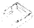
Fig. 1 is the decomposition diagram of first embodiment of the representative equipment that is used to carry out the insect supervision or prevents and treats of the present invention;
Fig. 2 is the perspective view of first embodiment of the representative equipment that is used to carry out the insect supervision or prevents and treats of the present invention;
To be that representative is of the present invention be used to carry out that insect monitors or the enlarged perspective of the outer cover of first embodiment of the equipment of control to Fig. 3;
To be that representative is of the present invention be used to carry out that insect monitors or the amplification plan view from above of the outer cover of first embodiment of the equipment of control to Fig. 4;
To be that representative is of the present invention be used to carry out that insect monitors or the enlarged side view of the outer cover of first embodiment of the equipment of control to Fig. 5;
Fig. 6 is the outer amplification inclinating view that covers under the not shown matrix situation of first embodiment of the representative equipment that is used to carry out the insect supervision or prevents and treats of the present invention;
To be that representative is of the present invention be used to carry out that insect monitors or the enlarged perspective of the cover cap of first embodiment of the equipment of control to Fig. 7;
To be that representative is of the present invention be used to carry out that insect monitors or the amplification face upwarding view of the cover cap of first embodiment of the equipment of control to Fig. 8;
Fig. 9 is the decomposition diagram of second embodiment of the representative equipment that is used to carry out the insect supervision or prevents and treats of the present invention;
Figure 10 is the perspective view of second embodiment of the representative equipment that is used to carry out the insect supervision or prevents and treats of the present invention;
Figure 11 is the perspective view of first and second embodiment of the representative equipment that is used to carry out the insect supervision or prevents and treats of the present invention;
Figure 12 is the plate plan view from above partly of the 3rd embodiment of the representative equipment that is used to carry out the insect supervision or prevents and treats of the present invention;
Figure 13 is the plate face upwarding view partly of the 3rd embodiment of the representative equipment that is used to carry out the insect supervision or prevents and treats of the present invention;
Figure 14 is the perspective view of the 3rd embodiment of the representative equipment that is used to carry out the insect supervision or prevents and treats of the present invention;
Figure 15 is the face upwarding view of the 3rd embodiment of the representative equipment that is used to carry out the insect supervision or prevents and treats of the present invention;
Figure 16 is the detailed cross sectional view along 16-16 line among Figure 14, and the 3rd plate of described equipment is arranged to link to each other with second plate of this equipment.
Figure 17 is the perspective view of the first and the 3rd embodiment of the representative equipment that is used to carry out the insect supervision or prevents and treats of the present invention;
Figure 18 is the plate plan view from above partly of the 4th embodiment of the representative equipment that is used to carry out the insect supervision or prevents and treats of the present invention;
Figure 19 is the plate face upwarding view partly of the 4th embodiment of the representative equipment that is used to carry out the insect supervision or prevents and treats of the present invention;
Figure 20 is the decomposition diagram of the 5th embodiment of the representative equipment that is used to carry out the insect supervision or prevents and treats of the present invention;
To be that representative is of the present invention be used to carry out that insect monitors or the enlarged perspective of the outer cover of the 5th embodiment of the equipment of control to Figure 21;
To be that representative is of the present invention be used to carry out that insect monitors or the amplification plan view from above of the outer cover of the 5th embodiment of the equipment of control to Figure 22;
Figure 23 is the outer amplification inclinating view that covers under the not shown matrix situation of the 5th embodiment of the representative equipment that is used to carry out the insect supervision or prevents and treats of the present invention;
This specification with the lower part together with description of drawings most preferred embodiment of the present invention.Although should be realized that in parameter area of the present invention and can realize multiple improved form, the embodiment of the invention disclosed herein is that the inventor thinks and is used under business environment realizing optimal mode of the present invention.
Following with reference to accompanying drawing so that describe the first embodiment of the present invention in detail, at first with reference to Fig. 1-8, they have illustrated equipment 10, equipment 10 comprises a plurality of outer covers 12, each outer cover all preferably the durable material by any in the various known polymer that comprises polystyrene and non-corrosive metal and wax constitute, described material is preferably resilient, be not biodegradable and prevent temperature and the ultraviolet radiation decay basically.With reference to Fig. 3 and 6, each outer cover 12 include first outer surface 13 that is generally the plane, relatively to second outer surface 14 that is generally the plane and define internal chamber 15, this chamber the edible base of at least a insect can be stopped 16 be included in part limit internal chamber 15 around in the inner surface 20.
Suitable matrix can be that any matrix of the pest species that monitors or prevent and treat and best usable fibers or modified fibrous substance of being suitable for constitutes as the material that contains vegetable fiber.The suitable material that contains vegetable fiber comprise be not limited to paper, paper products (100% primary paper, recycled writing paper or primary paper and recycled writing paper combination), cotton wool, card, cardboard, wooden particle or wood powder, such as can on market, press Methocel (recycled writing paper or vegetable fiber or other agricultural fibre the methylcellulose of (trade mark of Dow Chemical Company) trade (brand) name acquisition, HYDROXY PROPYL METHYLCELLULOSE, the HBMC.General available one or more solution that are made of bleaching compounds of these materials for example aqueous solution are bleached.Paper products and cotton wool can be veined or coarse selectively and can comprise a plurality of laminations selectively.
In order to use for the termite that is attracted or relies on to some extent or other pest species, enough moisture content, water can be increased to described matrix, this matrix can also comprise heat preserving agent or other moisture content adjusting device, so that generally the water content of internal chamber is maintained predetermined level.Can also provide make described matrix institute's pest species of monitoring or preventing and treating is attracted or is not added pheromone analogies or other composition of repulsion.
Described matrix also can comprise poison, preferably includes chronic and porous advances or comprises the into poison of described matrix.In addition, if wish under the situation of not carrying out insect control, to monitor suspicious insect activity, then can not have to use said matrix under the situation of poison.Suitable poison for example is chemical insecticide, insect growth regulator, IGR, microbial pathogens such described in PCT international document WO 93/23998 and WO 93/24011 or the toxin that comes from microbial pathogens.Preferable chemical insecticide is as described in the PCT international document WO 93/24011, those desinsection compounds in the claim of PCT international document WO 93/24011 more preferably, and that best is hexafluoro alditol (hexaflumuron).Also can use structurally and No. 5556883 disclosed hexafluoro alditol of United States Patent (USP) or No. 4833158 disclosed acyl urea compound of United States Patent (USP) such as fluorine tears alditol (flufenxuron).Other suitable poison can comprise the U.S. Provisional Application book submitted to No. the 08/745387th, the U.S. Patent application book of submitting on November 8th, 1996 and on November 8th, 1996 No. 60/029742, No. 60/029747 and No. 60/029748 disclosed some similar benzoyloxy phenyl carbamide compound, and, this paper has quoted PCT international document WO 96/32009, No. the 5556883rd, United States Patent (USP), No. the 60/029742nd, No. the 08/745387th, U.S. Patent application book and U.S. Provisional Application book, No. 60/029747 and No. 60/029748, this be because, these file specifications the multiple Pesticidal compound that can be used as the poison relevant with the present invention.
With reference to Fig. 4, by the ledge of removing one or more fragilities comprise big ledge 38 and be arranged between the internal upright 18 relatively to little ledge 39, can change the structure of outer cover first perforate 26, generally be to be enlarged to predetermined size.Certainly, should be realized that the described ledge of Fig. 4 only is exemplary, also can a plurality of positions on outer cover 12 be provided with other ledge.With reference to Fig. 3, each outer cover 12 of position of contiguous second outer surface 14 also define relatively to matrix grip block groove 40, be provided with near each matrix grip block groove 40 that flexible matrix grip block is fixing to refer to 41.
Shown in Fig. 7 and 8, cover cap 42 comprises is arranged to the cover cap pillar 45 adjacent with cover cap inner surface 44 near cover cap outer surface 43, cover cap inner surface 44 and a pair of relative corner on the diagonal of cover cap 42 that is generally the plane.Cover cap 12 preferably is made of the durable material any in multiple known polymer, non-corrosive metal and wax, and described durable material is preferably resilient, be not biodegradable and prevent temperature and the ultraviolet radiation decay basically.Each cover cap pillar 45 all defines cover cap perforate 46, and cover cap outer surface 43 defines a pair of and cover cap hole 46 corresponding perforated portions 47.As described below, when cover cap 42 was installed on outer cover 12, cover cap perforate 46 was arranged to align with the self tapping pillar 22 of outer cover 12.Cover cap 42 also comprises cover cap periphery crossette 48, and a plurality of closure passages 50 are arranged on cover cap crossette 48 places, and each closure passages 50 includes a locking smooth, that outwards give prominence to and refers to 52.Therefore, refer to that by making each locking 52 snap-fit in the corresponding fluting 36 of outer cover 12, cover cap 42 can be done engagement with second outer surface 14 of outer cover 12 and engage.In case engage with outer cover 12, cover cap 42 just can cover outer cover second perforate, 28 (see figure 4)s of outer cover 12 basically or it is stashed.Can be in prizing pull down and be positioned to make the cover cap 42 that engagement engages with outer cover 12 with the foliaceous instrument with groove 37.Refer to the crooked relatively of 52 phase cross-notchings 36 and each locking referred to that 52 are provided with in the fluting 36 that by locking cover cap 42 can be connected in any one outer cover 12 in detachable and removable mode.In addition, can with refer to except that aforementioned locking 52 with the multiple jockey of fluting 36 in any each cover cap 42 that makes be connected with outer cover 12 removably.For example, as previously mentioned, cover cap perforate 46 is arranged to align with self tapping pillar 22, therefore, when cover cap 42 engages with outer cover 12, can cover cap 42 be installed on outer cover 12 with unshowned spiral fastener such as self-tapping screw, described spiral fastener is arranged to pass each cover cap perforate 46 and is embedded in each self tapping pillar 22 in the mode of spiral.One or more moisturizing devices 54 preferably are installed, so that regulate the water content in the present invention on the cover cap inner surface 44.Moisturizing device 54 can constitute with the spongy material that any suitable material which can retain moisture for example can absorb water and for example be installed on the cover cap 42 with adhesive.Moisturizing device 45 can be used for the water content of internal chamber 15 is adjusted to predetermined level in some cases.
With reference to Fig. 1 and 6, by the protruding wing 58 being snap-fited in the matrix grip block groove 40, the matrix grip block 56 that is generally the plane that has the protruding wing 58 can be installed on outer cover 12 removably, matrix grip block 56 is then remained on the appropriate location (see figure 3) by the fixing finger 41 of matrix grip block.In addition, by make the protruding wing 58 for good and all be connected in the matrix grip block groove 40, by making 12 one-tenth integral body of matrix grip block 56 and outer cover or, matrix grip block 56 can being arranged to for good and all link to each other with outer cover 12 by suitably being connected in outer cover 12 with any matrix grip block 56 that makes in multiple securing member, adhesive or the similar device.Matrix grip block 56 is used for matrix 16 suitably is clamped in the appropriate position of internal chamber 15 and cover cap 42 can also be being demonstrated indication, warning or other for information about to the user when outer cover 12 is pulled down.
With reference to Fig. 1, the outer cover 12 that is called main outer cover 60 can be installed on installation surface 62 promptly by following mode near the known insect activity place: first outer surface, 13 (see figure 6)s of outer cover 12 are installed in installs on the surface 62.Thereby internal chamber 15 can interlink by outer cover first perforate 26 (see figure 6)s and installation surface 62, and outer cover first perforate 26 then is arranged on and installs surperficial 62 position adjacent places, so that provide a path between internal chamber 15 and installation surface 62.Surface 62 is installed can be positioned at indoor or outdoors, can be the building such as the room or the surface of trees, hedge or analog, and, be used to make insect suitably to select and prepare out installation surface 62 for intervention near surperficial 62 paths are installed by forming one.For example, can surface 62 be installed, main outer cover 60 can be installed to and install on the surface 62 by a unshowned securing member being arranged to pass each porose pillar 24 (see figure 3) and entering.Can be from present selecting said securing member the obtainable securing member that comprises bolt, nail, pin or similar device.In addition, can also main outer cover 60 be installed on installation surface 62 with other device that comprises magnetic devices, adhesive, caulked agent and adhesive tape.In order to monitor or prevent and treat insect or insect, if necessary, can as described the matrix 16 that includes insecticide be arranged in the internal chamber 15 of main outer cover 60, and moisture content be increased to moisturizing device 54 and cover cap 42 is snapped at second outer surface, 14 (see figure 3) places and do engagement with main outer cover 60 and engage.Also have, matrix 16 can not be equipped with poison in some cases, thereby, can before using poison, monitor the activity of the suspicious insect of facility on the ground, so that insect is prevented and treated.
In addition, can also removably cover cap 42 be fixed in main outer cover 60, thereby reduce illegally or the accidental chance of pulling down cover cap 42 with the spiral fastener that passes cover cap perforate 46 (see figure 7)s and enter self tapping pillar 22 (see figure 3)s.Cover cap 42 is used for covering basically outer cover second perforate 28 (see figure 4)s, and this perforate does not directly interlink (promptly not being in close proximity to said perforate) with arbitrary other perforate of other outer cover or is arranged on and the surperficial 62 position adjacent places of installation of described structure.Therefore, main outer cover 60 and cover cap 42 can remain on matrix 16 in the environment of internal chamber 15, and this environment preferably has limited relatively air movement so that disturb look for food insect or insect minimumly, and, when needed, described environment is unglazed basically and can controls the evaporation of moisture content.Outer cover 12 and cover cap 42 are kept apart matrix 16 and above-mentioned environment, thereby stoped in the face of people of the present invention and be exposed to poison, this be because, all can not be from any one outside opening of outer cover 12 or cover cap 42 near matrix 16, and outer cover 12 or cover cap 42 are used to also to prevent that moisture content from reducing to disappear can seal the base with multiple shape and size simultaneously and stop 16.As can be seen, cover cap 42 can move between the second place that the primary importance that covers outer cover second perforate 28 and outer cover second perforate 28 are not covered from above explanation.
When install surface 62 for nonplanar and define turnover insect of the present invention can be during through the edge from it, the ledge of one or more different sizes for example is set on main outer cover 60 shown in Fig. 1 and 2 like that, in Fig. 1 and 2, surface 62 is installed comprises edge 66, pass in and out insect of the present invention and can pass through this edge, can before being installed on the installation surface 62, take off big ledge 38 (see figure 3)s from main outer cover 60, and main outer cover 60 is installed in such a way promptly: the edge that outer cover 12 includes big ledge 38 in advance is configured to align with edge 66.Also have, one or more other ledges can be set in outer cover 12 little ledge 39 (see figure 3)s for example are set, it can take off from main outer cover 60 before being installed on the installed surface 62.Little ledge 39 has special advantage, wherein, for example, when the present invention is arranged to and the insect tunnel that raises when aligning, can be near insect of the present invention through the little perforate of perforate that is provided than big ledge 38.
By seeing through that transparent or semitransparent cover cap 42 is observed or by pulling down cover cap 42 so that expose matrix 16 from main outer cover 60 remaining when being no luminous environment basically through outer cover second perforate 28 (see figure 4)s, can monitor the consumption of insect, surface 62 can be installed simultaneously relatively main outer cover 60 is remained on the appropriate location matrix 16.Contain under the situation of matrix 16 of poison having consumed major part already, shown in the matrix 16 in being present in main outer cover 60 among Fig. 1, refer to that by locking thereby another outer cover 12 that 34 flutings 36 that snap-fit into main outer cover 60 will be called second outer cover 70 is mounted to main outer cover 60, can pass to insect with other poison with second outer cover 70.Second outer cover 70 similar substantially to main outer cover 60 usually and can with main outer cover 60 exchanges.Therefore, second outer cover 70 can be positioned to do engagement with main outer cover 60 and engage, second outer surface 13 of second outer cover 70 is arranged on second outer surface, the 14 position adjacent places with main outer cover 60, and first perforate 26 of the outer cover of second outer cover 70 can be at least in part aligns and interlinks with outer cover second perforate 28 of main outer cover 60.As a result, appear in the internal chamber 15 that is limited by main outer cover 60 insect freely shift-in second outer cover 70 internal chamber 15 and begin to consume wherein matrix 16, this is because the internal chamber of the main outer cover 60 and second outer cover 70 communicates with each other and connects.By cover cap 42 being installed on second outer cover 70 by above the above the mode of main outer cover 60 that just is installed to, can constitute the present invention with expansion, stacked form, so that other matrix 16 is provided down in the interference-free to a great extent environment of installing between surface 62 and the main outer cover 60 in bonding part, therefore, insect can move to the matrix 16 of second outer cover 70 from the matrix 16 of main outer cover 60 under the situation that its feed environment is had least interference.
Clearly, after most of matrix 16 of such used up second outer cover 70 of finding out by the activity that periodically monitors in second outer cover 70, by being installed on second outer cover 70, can increase another outer cover 12 with above the above the similar mode of main outer cover 60 that just second outer cover 70 is installed to.Can also increase another outer cover 12 by similar mode, thus the duplexer that can form the expansion that constitutes by outer cover 12 that is installed on the main outer cover 60.Increase outer cover 12 and can not influence the turnover corridor of formation or the existing network of path between termite gathering ground or nest and main outer cover 60 in the past.
Can remove and reconfigure the superimposed body that constitutes by outer cover 12 that is installed on main outer cover 60, thereby each outer cover 12 relative position in above-mentioned duplexer is interchangeable, perhaps, can removes wherein matrix 16 by used up substantially specific outer cover 12.And, thereby being placed on the matrix 16 that can make insect can gnaw through new outer cover 12 between the outer cover 12 of current insect activity and the main outer cover 60, new unworn outer cover 12 is back to main outer cover 60.
Should be realized that, although can pull down main outer cover 60 from surface 62 is installed in some cases, but, in general, main outer cover 60 should be stayed original position and be installed in and install on the surface 62, so as in surface 60 to be installed or install on the surface 60 and outer cover 12 in environment and main outer cover 60 between provide a familiar and stable bonding part for insect.
When matrix grip block 56 is installed on the outer cover 12 removably and after all or part of matrix 16 in having consumed outer cover 12 already, if necessary, can be by pulling down matrix grip block 56 from outer cover 12, will new replacement matrix 16 after removing any remainder of original matrix 16 put in the internal chamber 15 then by each protruding wing 58 reeve matrix grip block grooves 40 with matrix grip block 56, thus 16 settings of new replacement matrix are advanced in the outer cover 12.
In the second embodiment of the present invention, two or more outer covers 12 can be arranged to structure side by side, for example shown in Fig. 9-10, Fig. 9-10 shows a pair of outer cover 12 and a pair of cover cap 42, and they are installed in removably abreast installs on the surface 62.A pair ofly be used to make insect suitably to select and prepare out installation surface 62 for intervention by near each outer cover 12, forming, and each internal chamber 15 interlinks by corresponding outer cover first perforate 26 (see figure 6)s and the insect path that surperficial 62 places are installed near the path that surface 62 is installed.Remove little ledge 39 from the sides adjacent of each outer cover 12, directly lead to thereby make between the outer cover 12.Matrix 16 is arranged in the internal chamber 15 of each outer cover 12.Just as said, comprise that by making a securing member pass each porose pillar 24 (see figure 3)s and entering surface 62 to be installed or to utilize magnetic devices, adhesive, caulked agent and adhesive tape can be installed to outer cover 12 on the installation surface 62.Moisture content can be increased to moisturizing device 54, and each cover cap 42 snaps into the 12 do engagements of an outer cover and engages.As previously mentioned, can also cover cap 42 be fixed on the outer cover 12 with passing the spiral fastener that cover cap perforate 46 (see figure 7)s enter self tapping pillar 22 (see figure 3)s.When monitoring service shows the most of matrix 16 that has consumed already in the outer cover 12, can unload the paired outer cover 12 and be replaced from surface 62 is installed with a new replacement outer cover 12.Can before being installed to installed surface 62, remove the corresponding little ledge 39 of new replacement outer cover 12, therefore, installed surperficial 62 o'clock being installed to, new replacement outer cover 12 will be via interlinking with remaining original outer cover 12 because of the opening of removing on the outer cover 12 that little ledge 39 forms.In this way, the insect of feed can freely enter new replacement outer cover 12 so that consume other matrix 16 in remaining original outer cover 12.Therefore, when in remaining original outer cover 12, forming the insect feed, can replace remaining original outer cover 12, can surface 62 be installed relatively with stylish replacement outer cover 12 and continue to remain on the appropriate location with another outer cover 12.As can be seen, can similarly continue to be replaced with a outer cover 12 later on, only change the insect environment continuity that in the outer cover 12 arranged side by side one can obtain height in any given time in the outer cover 12.Certainly, should be realized that, when having used plural outer cover 12 by parallel construction, can change one or more selected outer covers 12, therefore, time change in the operating process being equipped with, needn't change the outer cover 12 that at least one insect is taken food just therein.
Can use first and second embodiment of the present invention simultaneously, as shown in figure 11, wherein, there are a plurality of outer covers 60 to be installed in and install on the surface 62, each outer cover 60 interlinks by a ledge and another outer cover 60 at least, and these outer covers 60 utilize the ledge of more than one suitable location and more than one other outer cover 60 to interlink.In addition, each outer cover 60 can have one or more second outer covers 70 mounted thereto.Certainly, outer cover 60 shown in Figure 11 and second outer cover, 70 arrays are to be exemplary arbitrarily and only, and each outer cover 60 ledge and other outer cover 60 on its each side by suitable location interlinks and have any amount of second outer cover 70.
In addition, should be realized that in another form, main outer cover 60 can be arranged to for good and all link to each other each other with second outer cover 70 in some cases.This respect, first outer surface 13 of one second outer cover 70 can be fixed into to be done engagement with one in stacked mode and main outer cover 60 or another second outer cover 70 second outer surface 14 and engages, and/or, can remove the little ledge 39 of an outer cover 60, thereby, when for good and all outer cover 60 being installed, being formed on opening on the outer cover 60 and can being positioned at the same manner (removing its little ledge 39) and being formed near the opening on another outer cover 60 by parallel construction.
In the third embodiment of the present invention, shown in Figure 12-16, equipment 10 comprise a plurality of thin and plate outer surfaces 151 (seeing Figure 12) of having the first flexible plate 150, each plate all to have to be generally the plane and relatively to the plate outer surface 152 (seeing Figure 13) that is generally the plane and define it and pass plate first perforate 154 (seeing Figure 13) of first plate 150 and comprise the detachable cap 154 of being arranged to cover plate first perforate 153.Cut out first joint-cutting 155 so that form detachable cap 154 simultaneously and plate first perforate 153 by passing first plate 150, detachable cap 154 can link to each other with 150 one-tenth integral body of first plate and with this first plate.Shown in Figure 12-13, first joint-cutting 155 does not constitute the continuous edge of detachable cap 154, this be because, have to connect and refer to 156, it is used at plate first perforate 153 places detachable cap 154 being connected in first plate 150.As will being illustrated, connect to tear and refer to 156 by grasping the protruding wing 157, pulling detachable cap 154, can pull down detachable cap 154 from first plate 150, thereby expose plate first perforate 153.In addition,, a unshowned releasable adhesive cover can be arranged on the outer surface 152 of plate,, therefore, can expose plate first perforate 153 by the releasable adhesive cover of dismantling so that replace detachable cap to cover plate first perforate 153 with reference to Figure 13.
Although be not main for purposes of the invention,, shown in Figure 13 and 15, each detachable cap 154 also can limit plate second perforate 160 of passing detachable cap 154 and comprise second detachable cap 162, and it is arranged to cover plate second perforate 160.Like this plate second perforate 160 of Xian Dinging on area less than plate first perforate 153.Cut out second joint-cutting 163 so that form second detachable cap 162 simultaneously and plate second perforate 160, the second detachable caps 162 can be whole with 154 one-tenth of detachable caps and link to each other with this detachable cap by passing detachable cap 154.According to above with regard to first joint-cutting, 155 described similar modes, second joint-cutting 163 does not constitute the continuous edge of second detachable cap 162, this be because, have to connect and refer to 156, it is used at plate second perforate 160 places second detachable cap 162 being connected in detachable cap 154.In addition, connect to tear and refer to 156, can pull down second detachable cap 162 from detachable cap 154, thereby expose plate second perforate 160 by grasping the second protruding wing 164, pulling second detachable cap 162.
Shown in Figure 12-16, equipment 10 comprise a plurality of thin and lower surfaces 168 (seeing Figure 12) of having the second flexible plate 166, each plate all to have to be generally the plane and relatively to be generally planar upper surface 170 (seeing Figure 13) and define the observation panel 172 (seeing Figure 14) that passes second plate 166 and comprise the observation detachable cap 174 of being arranged to cover observation panel 172.Second plate 166 cuts out arc joint-cutting 176 so that form observation detachable cap 174 and observation panel 172 simultaneously by passing, and observing detachable cap 174 can link to each other with 166 one-tenth integral body of second plate and with this second plate.Shown in Figure 12-13, joint-cutting fluting 176 does not constitute the continuous edge of observing detachable cap 174, this be because, have perforated edge 178, it is used for sentencing flexible mode at observation panel 172 and will observes detachable cap 174 and be connected in second plate 166.As will being illustrated, observe detachable cap 174 by doing the opening and closing campaign by relative observation panel 172 in the bending of perforated edge 178 places, and can also observe detachable cap 174 tearing along perforated edge 178 and to disassemble by grasping, thereby expose observation panel 172 from second plate 166.In addition, Figure 12-16 illustrated a plurality of thin and inner surfaces 182 (seeing Figure 12) of having the 3rd flexible plate 180, each plate all to have to be generally the plane and relatively to the outer surface that is generally the plane 183 (seeing Figure 13).
First, second and the 3rd plate 150,166 and 180 are can be with the monomer such as the polymer plate thin and have the flexible material that is generally the plane to constitute, and said polymer plate can metallize selectively or be retractable.First, second and the 3rd plate 150,166 and 180 can constitute with convenient with transparent or semitransparent material to be observed, or opaquely preferably approaches and have flexible matrix 184 (seeing Figure 14-16) that a unglazed basically environment is provided so that as will be described be.Although be not crucial for purposes of the invention, but, except belonging to the material that to keep out insect destruction basically, first, second and the 3rd plate 150,166 and 180 preferably are made of durable material, and described durable material is nondegradable basically and can prevents temperature and the ultraviolet radiation decay.
Can provide thin and flexible matrix 184 is arranged and it is chosen as the edible matrix of any insect, this matrix is suitable for that the pest species of being monitored uses and be flexible with monitoring, reducing or eliminating, thereby the ability of applying can be provided when third embodiment of the invention is installed on nonplanar surface in the best way.As just illustrate matrix employed, term " flexible " comprises the matrix that forms one or more continuous physical structures such as cardboard shape structure, described structure has higher flexible, and, term " flexible " comprises such as wooden particle, the matrix that the gathering colony or the aggregate by the individual particles structure of wood powder or similar substance and so on constitutes, the composition of this gathering colony or aggregate can be done relative motion each other, therefore, this gathering colony or aggregate can be made bending motion as a whole as described below when covering between first and second plate 150 and 166.Flexible matrix 184 generally comprises host material, and is flexible as long as matrix 184 can maintain, and described host material just can be from above-mentioned together with selecting the illustrated material of the above embodiment of the present invention.In addition, matrix 184 can comprise the poison such as above-mentioned poison.In addition, if under the situation of not carrying out insect control, monitor suspicious insect, then can not have to use flexible matrix 184 under the situation of poison.
Can be by folding along first fold line 185 and first plate 150 being connected together with second plate 166 along the first path side 186, thereby the lower surface 168 of second plate 166 is fixed on the inner surface 151 of plate, and said first passage side 186 is surrounded plate first perforate 153 and observation panel 172 at least in part.After this, flexible matrix 184 can be put in the volume 188 (seeing Figure 16) that is limited between each first plate 150 and second plate 166 and lower surface 168 is fixed in and seal in place in the inner surface 151 of plate, keep the flexible flexibility properties of matrix 184, first plate 150 and second plate 166 simultaneously by being preferably in the first path inner side, 190 places.Can by ordinary person in heat seal or the multiple present technique other known means realize said fixing.
With reference to Figure 12-16, by fold also pinched together along second fold line 192 each inner surface 182 of the 3rd plate 180 is installed on the upper face 170 of second plate 166 removably, so that carry out detachable installation along the alternate path 194 that surrounds observation panel 172 to small part.Be provided with and unfold line hole 193 so that pull down the 3rd plate 180 from second plate 166 as will be described.With the releasable adhesive 196 on the inner surface 182 that is arranged on the 3rd plate 180 or by any in multiple other detachable Installation Modes comprise installation with slide fastener, with the installation of hook and circulation fixator and with the installation of a plurality of buckles, can realize the 3rd plate 180 is installed on second plate 166 removably.
With reference to Figure 13, although can find out to use first plate 150 is installed to nonplanar multiple alternate manner of installing on the surface 197 in flexible and dismountable mode, but, can be installed in removably on surperficial 197 (the seeing Figure 14) of nonplanar installations near the position of insect plate outer surface 152 at the 3rd path 198 places that surround plate first perforate 153 with any in the multiple device such as foam adhesive tape 199 with first plate 150.Just as will be described, also can be by and after the second flexible outer casing device 200 be pulled down the 3rd plate 180 along unfolding that line hole 193 is dismantled, will be installed on removably by each flexible (promptly flexible) outer casing device 200 (seeing Figure 14) that first plate 150, second plate 166 and the 3rd plate 180 are constituted on the upper face 170 of second plate 166 of the second flexible outer casing device 200.
By forming first plate 150 that constitutes by flexible flexible material, second plate 166, the 3rd plate 180 and matrix 184, by first plate 150 is fixed on second plate 166, thereby by removably the 3rd plate 180 being installed on second plate 166 and, each flexible outer casing device 200 can being arranged to snugly be installed in the on-plane surface of an injustice like on the surface by removably first plate 150 being installed to nonplanar flexible flexibility that keeps them on surface 197 or another second plate 166 of installing.Certainly, should be noted that each flexible outer casing device 200 also can be installed on one equivalently and be generally on the surface on plane.And first plate 150, second plate 166 and the 3rd plate 180 can keep that such environment is arranged in the volume 188, and this environment has strict air movement, controlled water evaporates and is unglazed basically.
In the method for the invention, can pull down detachable cap 154 from first plate 150 of flexible outer casing device 200, so that expose flexible matrix 184.Under the situation that is provided with second detachable cap 162 already, can pull down second detachable cap 162 from detachable cap 154, simultaneously can keep detachable cap 154 to link to each other with first plate 150, so that expose the flexible matrix 184 than small size, and this area of the flexible matrix 184 that will expose under specific environment is to comprise insect activity, position feature and the environmental factor such as predetermined temperature and humidity range and selected according to multiple factor.Then, deposit with processing procedure in be equipped with under the situation of dismountable liner for foam adhesive tape 199 already, dismountable this dismountable liner, and, generally by be formed for making insect near surface 197 is installed suitably selected and prepare out installation surface 197 for intervention after, removably flexible outer casing device 200 is mounted to nonplanar installations surperficial 197 in the position of contiguous insect.With reference to Figure 14, in many cases, flexible outer casing device 200 preferably is installed, therefore, observe detachable cap 174 and can be arranged to and upwards to lift, do not help to stop the exterior materials bending to enter flexible outer casing device 200 so that do not form under the situations about closely linking to each other with second plate 166 at the 3rd plate 180.Because it is flexible around property character that each flexible outer casing device 200 has, so can removably flexible outer casing device 200 be mounted to bending, fluctuating is arranged, coarse, uneven or obviously be the surface of on-plane surface.
After flexible outer casing device 200 being mounted to nonplanar installation surface 197, peel off the 3rd plate 180 so that expose upper face 170 from second plate 166.After this, observing detachable cap 174 is having bore edges 178 places bending to leave second plate 166, thereby exposes the part of flexible matrix 184 via observation panel 172.Can be for example promptly be total moisture content of 65% to 70% by with syringe water is injected flexible matrix 184 in a plurality of positions concerning some is used in predetermined scope until water content, moisture content can be increased to flexible matrix 184.After having regulated water content, it is crooked backward so that cover observation panel 172 to observe detachable cap 174, and, the 3rd plate 180 is reinstalled to second plate 166, so flexible outer casing device 200 is available.
Then, by peeling the 3rd plate 180 from second plate 166 and making 174 bendings of observation detachable cap leave second plate 166, can monitor the consumption of insect to flexible matrix 184 so that expose flexible matrix 184 via observation panel 172.When second plate 166 and the 3rd plate 180 are made of transparent or semitransparent village's material, can observe detachable cap 174 bendings and leave under the situation of second plate 166 and directly observe the supervision that realizes flexible matrix 184 not peeling the 3rd plate 180 or not make from second plate 166 by seeing through second plate 166 and the 3rd plate 180.
Under the most situation that consumes the flexible matrix 184 that contains Poison already, can increase to the local of insect feed by the flexible matrix that will more contain poison or by locating to pull down the 3rd plate 180 and observe detachable cap 174 exposing observation panel 172 there being bore edges 178 to pull down unfolding line 193 (seeing Figure 12), thereby other poison is passed to insect from second plate 166 from second plate 166.Then, prepare to use another flexible outer casing device 200 as described above, and, thereby by align with original flexible outer casing device 200 that thereby plate first perforate 153 that makes original flexible outer casing device 200 observation panels 172 and another flexible outer casing device 200 aligns or by another flexible outer casing device 200 partly is mounted to original flexible outer casing device 200 and partly be mounted to nonplanar install observation panel 172 that surface 197 makes original flexible outer casing device 200 at least in part with plate first perforate 153 overlaids of another flexible outer casing device 200, said another flexible outer casing device 200 can be mounted to the upper face 170 of second plate 166 of original flexible outer casing device 200.Because each flexible outer casing device 200 has flexibility, so the second flexible outer casing device 200 can be arranged to snugly be mounted to original flexible outer casing device 200, and any in the available multiple flexible detachable installed part that comprises the foam adhesive tape realized this installation.In this way, insect can move to the flexible matrix 184 of the second flexible outer casing device 200 from the flexible matrix 184 of original flexible outer casing device 200.
Certainly, should be realized that, after the major part of the flexible matrix 184 that has consumed the second flexible outer casing device 200 already, can be by by just the second flexible outer casing device 200 being mounted to original bendable and by outer casing device 200 described similar modes the second flexible outer casing device 200 being installed and being increased by one the 3rd flexible outer casing device 200 with above.In addition, can increase other flexible outer casing device 200 by similar mode, thereby, the flexible or flexible superimposed body that constitutes by flexible outer casing device 200 can be formed.Also have, owing to removably each flexible outer casing device 200 is mounted to nonplanar installation surface 197 or is mounted to another flexible outer casing device 200, so can dismantle and re-assembly the superimposed body that constitutes by flexible outer casing device 200, thereby, the relative position of each the flexible outer casing device 200 in this superimposed body can change, perhaps, can remove its flexible matrix 184 and be consumed flexible outer casing device 200 already basically.Although can remove original flexible outer casing device 200 from nonplanar installation surface 197 in some cases, but, in general, original flexible outer casing device 200 should be stayed original position and be installed on the nonplanar installation surface 197, so as nonplanar environment in the surface 197 is installed and is installed between the flexible outer casing device 200 on original flexible outer casing device 200 provide a familiar and stable bonding part for insect.
Clearly, when suitably selecting the relative size of outer cover 12 and flexible outer casing device 200, can use the of the present invention first and the 3rd embodiment simultaneously.For example, as shown in figure 17, main outer cover 60 can be installed on installs surface 62, second outer cover 70 can be installed on main outer cover 60, and, plate first perforate 153 that can prepare to use flexible outer casing device 200 and outer cover second perforate 28 by flexible outer casing device 200 being arranged to second outer cover 70 and flexible outer casing device 200 as described above aligns and flexible outer casing device 200 is mounted to second outer surface 14 of second outer cover 70, and any in the available multiple flexible detachable installed part that comprises the foam adhesive tape is mounted to second outer cover 70 with flexible outer casing device 200.Under the situation that does not have second outer cover 70, flexible outer casing device 200 can be mounted to main outer cover 60, in addition,, can be by using the third embodiment of the present invention with aforementioned on all four mode and fourth embodiment of the invention.
In the fourth embodiment of the present invention, shown in Figure 18 and 19, each is first with the thin of the 3rd plate 150 and 180 monomer available and have the flexible opaque material that is generally the plane to become integrally to form, and each second plate 166 is then available to be approached and have the flexible transparent or semitransparent material that is generally the plane to constitute respectively.By linking together along the first path side 168 and the first path exterior lateral sides 191, the inner surface 151 of the plate of first plate 150 can be fixed on the lower surface 168 of second plate 166, then flexible matrix 184 be put into volume 188 and in the first path inner side, 19 place's seal in place.Under the situation that second plate 166 is made of transparent or semitransparent material,, can realize insect is consumed the supervision of flexible matrix 184 by peelling off the 3rd plate 180 so that expose the second transparent or semitransparent plate 166 from second plate 166.In addition, observing detachable cap 174 can have bore edges 178 places bending to leave second plate 166, directly checks flexible matrix 184 so that see through observation panel 172.
Have in the fifth embodiment of the present invention, shown in Figure 20-23, equipment 10 comprises a plurality of outer covers 312, each outer cover all preferably is made of the durable material a kind of in the multiple known polymer that comprises polystyrene and non-corrosive nonmetal and wax, preferably resilient, nondegradable and can prevent the decay of temperature and ultraviolet radiation basically of described durable material.Each outer cover 312 is all similar but be not illustrated as the square configuration that has as the illustrated outer cover 12 of Fig. 1-6 with the outer cover 12 of first embodiment.Each outer cover 312 comprise first outer surface 313 (seeing Figure 23) that is generally the plane, relatively to second outer surface 314 (seeing Figure 21) that is generally the plane and inner surface around 320 (seeing Figure 21) in define internal chamber 315, this chamber can comprise at least one matrix 316 and generally comprise two matrix 316, and inner surface 320 then partly defines internal chamber 315.Can be from above-mentioned together with selecting suitable matrix the illustrated matrix of the previous embodiment of the present invention, and this matrix can comprise the poison of selecting or not comprise poison from the above poison.
With reference to Figure 21, self tapping pillar 322 relatively to first corner 323 near be installed on inner surface 320, two porose pillars 324 (only showing a porose pillar 324 among Figure 21) relatively to second corner 325 near be installed on inner surface 320 in a similar fashion, and two porose pillars 327 (only showing a porose pillar 327 among Figure 21) are installed on inner surface 320 in a similar fashion near self tapping pillar 322.Each outer cover 312 defines: outer cover first perforate 326 (seeing Figure 23), and it is arranged between first outer surface 313 and the internal chamber 315; And, outer cover second perforate 328 (seeing Figure 22), it is arranged between second outer surface 314 and the internal chamber 315.Near first outer surface 313 position, each outer cover 312 also comprises peripheral crossette (flange) 330, near second outer surface 314 position, each outer cover 312 comprises peripheral ladder 322, therefore, first outer surface 313 of each outer cover 312 can be done to mesh and engage with second outer surface 314 of another outer cover 312.Be provided with a plurality of passages 333 at each peripheral crossette (flange) 330 place, each passage includes locking barb, that outwards give prominence to and refers to 334 (seeing Figure 23), and this locking refers to be used for the effect of a unidirectional clamping close device.Each ladder 332 place is positioned with a plurality of inwardly outstanding grooves 335, and they are arranged to corresponding with the passage 333 of another outer cover 312.Each groove 335 comprises fluting 336, therefore, to make joggle(d) joint fashionable with second outer surface 314 of another outer cover 312 when first outer surface 313 of outer cover 312 is positioned to, by each locking being referred to 334 snap-fit into a corresponding fluting 336, an outer cover 312 can be able to be mounted to another outer cover 312.Refer to the crooked relatively of 334 phase cross-notchings 336 and each locking is referred to that 334 are provided with a fluting 336 by locking, can make each outer cover 312 be connected in other outer cover 312 in detachable and removable mode.Can also by with suitable securing member for example nut inject via the porose pillar 327 of outer cover 312 in the porose pillar 327 of another outer covers 312 and outer cover 312 be connected in other outer cover 312 in detachable and removable mode.Can use putting in such as screwdriver to prize the outer cover 12 that is positioned to mesh joint with the dismounting of the foliaceous instrument in one of groove 337 in a manner described, described prizing with groove then is being limited near second outer surface 314 on each outer cover 312, if the outer cover 312 that is meshed is connected together with securing member by securing member being injected porose pillar 327, then can pull down this securing member from porose pillar 327.In addition, can with refer to except that aforementioned locking with fluting and/or securing member and porose pillar 327 multiple jockey in any each outer cover 312 that makes be connected with other outer cover 312 in detachable and removable mode.
By remove one or more ledges comprise big ledge 338 and be arranged between the internal upright 318 relatively to little ledge 339, can change the structure of outer cover first perforate 326.Certainly, should be realized that Figure 21 and 22 described ledges only are exemplary, can be provided with other ledge on a plurality of positions on the outer cover 312.In the contiguous little ledge 339 and the position of internal upright 318, outer cover 312 also comprises four partially perforated pillars 340, and they are installed on the inner surface 320.
With reference to Figure 20, the cover cap of the cover cap 342 and first embodiment 42 is similar but be not illustrated as the square configuration that has as the illustrated cover cap 42 of Fig. 1-2 and 7-8.On the contrary, cover cap 342 is illustrated as in Figure 20 and only has rectangular shape.All the cover cap 42 with first embodiment is identical in all others for cover cap 342.With reference to Figure 20, cover cap 342 comprises the cover cap outer surface 343 that is generally the plane and is generally the cover cap inner surface 344 on plane, it relative with cover cap outer surface 343 to.Although do not show, cover cap 342 also comprise a pair of on the diagonal of cover cap 342 relatively to corner near be arranged to the cover cap pillar adjacent with cover cap inner surface 344.Similar with the cover cap 42 of first embodiment, cover cap 342 preferably is made of durable material any in multiple known polymer, non-corrosive metal and wax, and described durable material is preferably resilient, be not biodegradable and prevent temperature and the ultraviolet radiation decay basically.Each cover cap pillar all defines the cover cap perforate 346 of therefrom passing, and cover cap outer surface 343 defines a pair of boring part 347, and they are corresponding with cover cap perforate 346.As will illustrating, when cover cap 342 was mounted on the outer cover 312, cover cap perforate 346 was arranged to align with the self tapping pillar 322 (seeing Figure 21) of outer cover 312.Cover cap 342 also comprises cover cap periphery crossette 348, has a plurality of closure passages 350 to be arranged on cover cap periphery crossette 348 places, and each closure passages 350 includes a level and smooth outwards outstanding cover cap and refers to 352.Therefore, cover cap 342 can snap-fit in the corresponding fluting 336 of of outer cover 312 and does engagement with second outer surface 314 (seeing Figure 21) of outer cover 312 and engage by each cover cap being referred to 352.Can in prizing, be positioned to make the cover cap 342 that engagement engages with outer cover 312 with the dismounting of foliaceous instrument with groove 337.Refer to the crooked relatively of 354 phase cross-notchings 336 and each cover cap is referred to that 352 are provided with a fluting 336 by cover cap, can make each outer cover 342 be connected in other outer cover 312 in detachable and removable mode.In addition, can with refer to except that aforementioned cover cap 352 with the multiple jockey of fluting 336 in any each outer cover 342 that makes be connected with other outer cover 312 removably.For example, as previously mentioned, cover cap perforate 346 is arranged to align with self tapping pillar 322, therefore, when cover cap 342 engages with outer cover 312, available unshowned spiral fastener such as tapping screw further is installed to cover cap 342 on the outer cover 312, and said spiral fastener then is arranged to pass in each cover cap perforate 346 and each the self tapping pillar 322 of mode embedding with spiral.Best is, cover cap inner surface 344 is equipped with one or more moisturizing devices 354, and they can be used for regulating the moisture content resultant in the present invention.Moisturizing device 354 can constitute with the spongy material that any suitable material which can retain moisture for example absorbs water and for example be installed on the cover cap inner surface 344 with adhesive.
With reference to Figure 20 and 23, the matrix grip block 35 that is generally the plane often is the outer surface 359 on plane and the inner surface 361 that is generally the plane, it relative with outer surface 359 to.The pillar 358 outstanding inner surfaces 361 that leave.In general, have four pillars 358, and pillar 358 generally extension vertically leaves inner surface 361.Can inject by each pillar 358 in the partially perforated pillar 340 of outer covers 312 and matrix grip block 356 is mounted to outer cover 312 matrix grip block 356.Matrix grip block 356 can forever or be removably installed in outer cover 312.For example, can by the present technique expert known mode process pillar 356 and partially perforated pillar 340, therefore, matrix grip block 356 can forever or be removably installed in outer cover 312.In a most preferred embodiment of the present invention, but following manner processes pillar 358 and partially perforated pillar 340 promptly: in case pillar 358 is received in the partially perforated pillar 340, anyly will all can cause pillar 358 to disconnect mutually with the inner surface 361 of matrix grip block 356 from the trial that outer cover 312 is pulled down matrix grip block 356 and separate.As the method for the matrix 316 that replaces with new matrix 316 running out, generally use this structure to stop the operating personnel of control of insect to pull down matrix grip block 356 from outer cover 312.It shall yet further be noted that matrix grip block 356 can be whole with 312 one-tenth of outer covers or otherwise suitably link to each other with outer cover 312 with any in multiple securing member, adhesive or the similar substance.Matrix grip block 356 is used for suitably matrix 316 being clamped in the appropriate location of internal chamber 315 and can showing indication, warning and for information about to the user when outer cover 312 is pulled down cover cap 342.
Can be in said method of the present invention by with the equipment 10 that uses the 5th embodiment that comprises outer cover 312 together with the illustrated identical mode of first embodiment and outer cover 12.Install surface 362 be on-plane surface and define the insect of the present invention of coming in and going out can be under the situation at the edge 366 of its process, can on main outer cover 360, be provided with one and become a plurality of ledges with different size and by using above-mentioned ledge with regard to the illustrated same way as of main outer cover 60 with above.
By seeing through that transparent or semitransparent cover cap 342 is observed or by covering 360 from the principal and subordinate when being unglazed environment substantially and pull down cover cap 342 maintaining so that expose matrix 316 via outer cover second perforate 328 (seeing Figure 22), can monitor the consumption of insect, surface 362 can be installed simultaneously relatively main outer cover 360 is remained on the appropriate location matrix 316.Under the most situation that has consumed the matrix 316 that contains Poison already, shown in the matrix 316 in being present in main outer cover 360 among Figure 20, refer to that by cover cap 334 (seeing Figure 23) snap-fit into another outer cover 312 that will be called second outer cover 370 in the fluting 336 (seeing Figure 21) of main outer cover 360 and are mounted to main outer cover 360, thereby other poison can be passed to insect second outer cover 370.According to this mode, second outer cover 370 is positioned to do engagement with main outer cover 360 and engages, it is adjacent with second outer surface 314 (seeing Figure 21) of main outer cover 360 that the outer surface 313 (seeing Figure 23) of second outer cover 370 is arranged to, and outer cover first perforate 326 (seeing Figure 21) of second outer cover 370 interlinks with outer cover second perforate 328 (seeing Figure 22) of main outer cover 360.Therefore, be present in the internal chamber 315 that main outer cover 360 limited insect freely shift-in second outer cover 370 internal chamber 315 and begin to consume wherein matrix 316.By cover cap 342 being mounted to main outer cover 360 by before just being mounted to main outer cover 360 described modes, can constitute the present invention by the stacked form that expands, thereby can in such environment, provide matrix 36, in said environment, the bonding part of installing between surface 326 and the main outer cover 360 is interference-free to a great extent, therefore, have under the situation of minimum influence at the feed environment to insect, insect can move to the matrix 316 of second outer cover 370 from the matrix 316 of main outer cover 360.
Clearly, after the major part of the matrix 316 that as shown in basis periodically monitors the work of the activity in second outer cover 370, had consumed second outer cover 370 already, by second outer cover 370 being installed, can increase another outer cover 312 by the similar mode illustrated with before just second outer cover 370 being mounted to main outer cover 360.Can increase other outer cover 312 by similar mode, thereby form a superimposed body of expansion that constitutes by outer cover 312 that is installed on the main outer cover 360.Increase outer cover 312 and can not influence the previous discrepancy corridor that between termite gathering ground one-tenth nest and main outer cover 360, forms or the existing network of path.
Can dismantle and re-assembly the superimposed body that constitutes by outer cover 312 that is installed on the main outer cover 360, thereby, the relative position of each outer cover 312 in this superimposed body can exchange, and perhaps, can remove the selected outer cover 312 that wherein matrix 316 had been consumed already basically.And, new unworn outer cover 312 is placed between outer cover 312 with current insect activity and the main outer cover 360 can makes insect gnaw through the matrix 316 of new outer cover 312 to be back to main outer cover 360.
Should be realized that, although can remove main outer cover 360 from surface 362 is installed in some cases, but, in general, main outer cover 360 should be stayed original position and be installed in and install on the surface 362, so that the environment in surface 362 is installed and be installed between the outer cover 312 on the main outer cover 360 and provide a familiar and stable boundary part for insect.
When matrix grip block 356 is installed on the outer cover 312 removably and after all or part of matrix 316 in having consumed outer cover 312 already, if necessary, can be by pulling down matrix grip block 356 from outer cover 312, will new replacement matrix 316 after removing any remainder of original matrix 316 put in the internal chamber 315 then by partially perforated pillar 340 with the pillar 358 reeve outer covers 312 of matrix grip block 356, thus 316 settings of new replacement matrix are advanced in the outer cover 312.
With regard to as described in outer cover 12 and the second embodiment of the invention, can also two or more outer covers 312 be arranged to parallel construction as above by same mode.In addition, with regard to outer cover 12 with use simultaneously as described in the present invention first and second embodiment, outer cover 312 can also be arranged to arranged side by side and stacked form, wherein as above, by one or more second outer covers 370 are mounted to outer cover 312, each outer cover 312 can play main outer cover 360.
The present invention pays close attention to multiple operable method and apparatus, the content of utilizing this paper to provide, and expert of the present invention is best ad hoc approach and equipment to specific target pest and environmental facility as can be seen.Although this explanation mainly lays particular emphasis on the control of termite,, should be realized that the version of said method and equipment and they are found out at an easy rate the applicable performance of insect except that termite and insect and can be utilized by the expert of present technique.With most preferred embodiment the present invention had been described already, clearly, under the situation of the practice that does not break away from the scope of the invention and personnel of the present invention, the present invention has the multiple improved form and the embodiment of the limit of power that belongs to expert in the present technique.Specifically, under the situation that not necessarily breaks away from the scope of the invention, can use the geometry except that rectangle or square outer cover and equipment.Therefore, scope of the present invention is restricted to the described content of scope of following claim.
Claims (12)
Applications Claiming Priority (2)
| Application Number | Priority Date | Filing Date | Title |
|---|---|---|---|
| US1642296P | 1996-04-29 | 1996-04-29 | |
| US60/016,422 | 1996-04-29 |
Publications (2)
| Publication Number | Publication Date |
|---|---|
| CN1216895A CN1216895A (en) | 1999-05-19 |
| CN1108748C true CN1108748C (en) | 2003-05-21 |
Family
ID=21777044
Family Applications (1)
| Application Number | Title | Priority Date | Filing Date |
|---|---|---|---|
| CN97194223A Expired - Lifetime CN1108748C (en) | 1996-04-29 | 1997-04-16 | Method and apparatus for pest monitoring or control |
Country Status (17)
| Country | Link |
|---|---|
| US (2) | US6058646A (en) |
| EP (1) | EP0902619B1 (en) |
| JP (1) | JP3777557B2 (en) |
| CN (1) | CN1108748C (en) |
| AU (1) | AU726871B2 (en) |
| BR (1) | BR9708884A (en) |
| ES (1) | ES2206705T3 (en) |
| GT (1) | GT199700050A (en) |
| ID (1) | ID16842A (en) |
| IL (1) | IL126599A (en) |
| MY (1) | MY123786A (en) |
| PA (1) | PA8428901A1 (en) |
| SG (1) | SG83754A1 (en) |
| TW (1) | TW361991B (en) |
| UY (1) | UY24525A1 (en) |
| WO (1) | WO1997040667A1 (en) |
| ZA (1) | ZA973652B (en) |
Families Citing this family (70)
| Publication number | Priority date | Publication date | Assignee | Title |
|---|---|---|---|---|
| US5927001A (en) | 1997-02-03 | 1999-07-27 | Fmc Corporation | Sectional bait station |
| EP0968652A4 (en) * | 1997-11-25 | 2001-05-11 | Takeda Chemical Industries Ltd | Wood preservative, rot- and insect-proofing system, and bait kit |
| US6343434B1 (en) * | 1999-02-16 | 2002-02-05 | John Michael Petti | Pest-activated bait dispensing system |
| US6234111B1 (en) * | 1999-04-29 | 2001-05-22 | Research Diets, Inc. | Animal feeder, feeder mount, feeder monitor, and feeder monitoring network |
| US6189259B1 (en) * | 1999-06-14 | 2001-02-20 | S. C. Johnson & Son, Inc. | Insect bait-and-switch delivery apparatus |
| US6637150B1 (en) | 1999-10-13 | 2003-10-28 | University Of Florida | Below ground non-edible foraging matrix configurations for arthropod control |
| US6606816B2 (en) * | 1999-10-13 | 2003-08-19 | University Of Florida | Ground surface non-edible foraging matrix configurations for arthropod control |
| DE10000326A1 (en) * | 2000-01-07 | 2001-07-19 | Klaus Hoppe | Insect trap for insertion into e.g. switch cabinet or cable conduit comprises bait box with open end which is inside housing and closed end outside it, box being held in place by clips |
| US6370814B1 (en) * | 2000-01-20 | 2002-04-16 | David H. Curtis | Conformable termite bait container for walls and corners |
| US6374536B1 (en) * | 2000-06-27 | 2002-04-23 | Lawrence Washburn | Subterranean termite monitor and method |
| US6370811B1 (en) * | 2000-07-31 | 2002-04-16 | Michael J. Masterson | Apparatus and method for monitoring termite activity |
| US6584728B2 (en) * | 2001-02-15 | 2003-07-01 | Harold W. Aesch, Jr. | Termite bait station and method of service |
| US6969512B2 (en) * | 2001-03-05 | 2005-11-29 | The University Of Florida Research Foundation, Inc. | Devices and methods for eliminating termite colonies |
| US6716421B2 (en) | 2001-03-05 | 2004-04-06 | University Of Florida Research Foundation, Inc. | Devices and methods for eliminating termite colonies |
| US7030156B2 (en) | 2001-03-05 | 2006-04-18 | University Of Florida Research Foundation, Inc | Devices and methods for eliminating termite colonies |
| US6964124B2 (en) * | 2001-03-05 | 2005-11-15 | University Of Florida Research Foundation, Inc. | Devices and methods for eliminating termite colonies |
| US6581325B2 (en) | 2001-03-26 | 2003-06-24 | Gordon Laboratories, Inc. | Device and method for controlling termites |
| US6526692B2 (en) | 2001-06-15 | 2003-03-04 | Clark Pest Control Of Stockton, Inc. | Method and apparatus for in-ground subterranean termite detection |
| AUPR744301A0 (en) * | 2001-09-03 | 2001-09-27 | CARPENTER, Bradley John | Apparatus for and methods of inhibiting termite infestation |
| US20040031190A1 (en) * | 2001-10-12 | 2004-02-19 | Collins James Robert | System and methods for monitoring arthropods |
| US6678995B1 (en) * | 2002-01-16 | 2004-01-20 | Jeff Carviel | Flying insect control device |
| ES2311695T3 (en) | 2002-03-22 | 2009-02-16 | University Of Florida Research Foundation, Inc. | HERMETICALLY SEALED BAITS FOR UNDERGROUND TERMITES. |
| CN100475032C (en) | 2002-03-22 | 2009-04-08 | 佛罗里达大学研究基金会公司 | A semiochemical reservoir to attract subterranean termites tunneling in soil |
| US7051474B1 (en) * | 2002-04-30 | 2006-05-30 | Tesh William A | Insect monitor and method |
| US20060162236A1 (en) * | 2002-08-18 | 2006-07-27 | Ecospan Consulting Services Pty Ltd | Detection and elimination of termites |
| BR0315369B1 (en) | 2002-10-25 | 2011-02-08 | camouflaged termite monitoring device and termite monitoring method in one site. | |
| EP1606174B1 (en) * | 2003-03-12 | 2006-07-19 | Pallet Detection Systems Ltd | Pallet load-infestation monitoring |
| WO2004084625A2 (en) * | 2003-03-22 | 2004-10-07 | Vickery Ethan | Tamper resistant weighted rodent and insect bait station |
| US20060005462A1 (en) * | 2004-07-08 | 2006-01-12 | Ballard James B | Devices and methods for monitoring and controlling arthropods |
| US20060053682A1 (en) * | 2004-09-13 | 2006-03-16 | Michael Goldstein | Corner-fitting escape-proof repeating animal trap |
| US7377072B2 (en) * | 2005-05-31 | 2008-05-27 | S.C. Johnson & Son, Inc. | Bait station |
| US20090300968A1 (en) * | 2006-03-14 | 2009-12-10 | Syngenta Crop Protection, Inc. | Bait station for termite control |
| US8720107B1 (en) | 2006-04-11 | 2014-05-13 | Vm Products Inc. | Tamper-resistant fly control station and methods for using the same |
| US20080052982A1 (en) * | 2006-08-30 | 2008-03-06 | Windsor Earl S | Wood-Boring Insect Trap |
| US7669363B2 (en) * | 2006-10-10 | 2010-03-02 | Steven Frisch | Rodent bait station |
| US7685778B2 (en) * | 2007-06-04 | 2010-03-30 | Edell James J | Rodent guard |
| USD587334S1 (en) | 2007-06-28 | 2009-02-24 | Whitmire Micro-Gen Research Laboratories, Inc. | Termite station container |
| US8387306B2 (en) | 2007-06-28 | 2013-03-05 | Basf Corporation | Method of monitoring and controlling termites with heat-treated wood |
| US8407933B2 (en) | 2007-06-28 | 2013-04-02 | Basf Corporation | Above-ground termite station |
| USD587779S1 (en) | 2007-06-28 | 2009-03-03 | Whitmire Micro-Gen Research Laboratories, Inc. | Termite station container |
| MY152693A (en) * | 2007-07-26 | 2014-11-28 | Dow Agrosciences Llc | Techniques for maintaining palatability of a bait material in a pest control device |
| US20090090044A1 (en) * | 2007-10-08 | 2009-04-09 | Foley Terrence J | In-wall pest control device |
| US20090094884A1 (en) * | 2007-10-12 | 2009-04-16 | Whitmire Micro-Gen Research Laboratories, Inc. | Termite station with replaceable cartridge |
| US7874098B2 (en) * | 2008-08-05 | 2011-01-25 | Vm Products, Inc. | Weighted rodent bait stations and related methods |
| WO2010028378A2 (en) | 2008-09-08 | 2010-03-11 | Vm Products Inc. | Weighted rodent bait stations and related methods |
| US8266839B2 (en) * | 2009-02-13 | 2012-09-18 | Alan Bernard | Insect bait station with snap-open cartridge and cradle |
| USD667526S1 (en) | 2010-02-10 | 2012-09-18 | Larry Covington | Bait station |
| US8701336B2 (en) * | 2010-08-12 | 2014-04-22 | Daniel J. Kay | Pest control device |
| US9532564B1 (en) * | 2011-01-03 | 2017-01-03 | Oms Investments, Inc. | Tamper-resistant rodent bait station |
| US8959829B2 (en) | 2012-04-06 | 2015-02-24 | Daniel Kay | Rodent trap mounting member and method |
| AU2013100496B4 (en) * | 2012-06-20 | 2014-01-16 | Ion Leslie Staunton | Method and device for attracting and baiting termites |
| AU2014223364C1 (en) | 2013-03-01 | 2018-02-15 | Arthropod Biosciences, Llc | Insect trap device and method of using |
| AU2013204887B2 (en) * | 2013-04-12 | 2016-05-26 | Staunton, Ion Leslie MR | Bait delivery |
| US9629352B2 (en) * | 2013-11-13 | 2017-04-25 | Leonard E. Anderson | Animal entrapment device and system |
| ES2952696T3 (en) | 2013-11-27 | 2023-11-03 | Procter & Gamble | Insect catching device |
| SG11201608318WA (en) * | 2014-04-26 | 2016-11-29 | Procter & Gamble | Insect trap device and method of using |
| WO2015179899A1 (en) | 2014-05-28 | 2015-12-03 | Pesense Pty Ltd | Pest detection |
| CN107404866A (en) | 2015-01-12 | 2017-11-28 | 宝洁公司 | Insect trapping device and method of use |
| AU2016374488A1 (en) * | 2015-12-17 | 2018-07-05 | Bradley John CARPENTER | Construction materials and methods for insect monitoring |
| US20170188565A1 (en) * | 2016-01-05 | 2017-07-06 | Creative Pest Design Inc. | Pest control system with improved usability |
| USD829846S1 (en) | 2017-05-10 | 2018-10-02 | Vm Products, Inc. | Pest trap |
| USD828484S1 (en) | 2017-05-10 | 2018-09-11 | Vm Products, Inc. | Pest trap |
| US12256723B2 (en) | 2017-12-21 | 2025-03-25 | Pesense Pty Ltd | Mounting and positioning device for an electronic sensor in a termite monitor |
| USD844759S1 (en) * | 2017-12-28 | 2019-04-02 | David Kresge | Plastic bird guard for dryer vent |
| US11523601B2 (en) * | 2018-10-26 | 2022-12-13 | Woodstream Corporation | Insect control device and method for household outdoor garbage receptacles |
| US12171234B2 (en) * | 2019-03-08 | 2024-12-24 | Ypf Tecnología S.A. | Sexual attraction pheromone of tribolium castaneum and insect control device |
| JP6618102B1 (en) * | 2019-09-13 | 2019-12-11 | 株式会社トラスト | Termite guidance device, installation structure of this termite guidance device, and installation method of this termite guidance device |
| ES1247524Y (en) * | 2019-12-20 | 2020-08-28 | Probodelt S L | ATTRACTING DEVICE FOR DIPTERS |
| US20240180137A1 (en) * | 2022-07-19 | 2024-06-06 | Bayer Cropscience Kk | Cartridge, anti-termite device, and its application method |
| WO2026024915A1 (en) * | 2024-07-23 | 2026-01-29 | Trapmaster Technologies, LLC | Secure bait box with secure bait and attachment system |
Family Cites Families (65)
| Publication number | Priority date | Publication date | Assignee | Title |
|---|---|---|---|---|
| US520715A (en) * | 1894-05-29 | Sticky fly-paper | ||
| US859636A (en) * | 1906-09-04 | 1907-07-09 | Fred Stimson Welch | Insect-trap. |
| US911794A (en) * | 1908-02-04 | 1909-02-09 | George T Williams | Record-packet. |
| US1013514A (en) * | 1911-07-03 | 1912-01-02 | Charles F Penn | Poison-receptacle. |
| US1087058A (en) * | 1913-07-23 | 1914-02-10 | John A V Zielfeldt | Fly-catcher. |
| GB148775A (en) * | 1918-04-16 | 1921-08-18 | Vickerys Ltd | Improvements in or relating to paper calendering rolls or the like |
| US1477157A (en) * | 1920-08-20 | 1923-12-11 | Harold L Tuers | Envelope |
| US2088335A (en) * | 1936-10-16 | 1937-07-27 | Hubert J Michaels | Insect feeder |
| US2725322A (en) * | 1954-09-03 | 1955-11-29 | Brady Co W H | Protected adhesive article |
| US2808679A (en) * | 1955-12-13 | 1957-10-08 | Paramount Paper Products Co | Pest exterminator |
| US2837861A (en) * | 1957-07-24 | 1958-06-10 | Sr James T Graham | Outdoor insecticide container |
| US3017717A (en) * | 1960-01-05 | 1962-01-23 | David H Caubre | Ant vault |
| US3173223A (en) * | 1963-09-24 | 1965-03-16 | Nutrilite Products | Insect killing device |
| US3624953A (en) * | 1969-12-10 | 1971-12-07 | Frank P Crosby | Termite control system |
| US3717297A (en) * | 1971-03-11 | 1973-02-20 | Creative Posters Inc | Disc record carrier |
| US3940875A (en) * | 1972-11-15 | 1976-03-02 | Basile Mario J | Method of treating soil for controlling termites and the like |
| US3858346A (en) * | 1973-01-29 | 1975-01-07 | Allied Chem | Control of subterranean termites |
| JPS5081868A (en) * | 1973-11-13 | 1975-07-02 | ||
| US3906656A (en) * | 1974-01-24 | 1975-09-23 | Vincent D Burke | Anti-coagulant bait package for rodents including methods of making and using same |
| US4043073A (en) * | 1974-08-09 | 1977-08-23 | Basile Mario J | Method of treating soil for controlling termites and the like |
| GB1561901A (en) * | 1975-08-06 | 1980-03-05 | Atomic Energy Of Australia | Control of insects |
| DE2644217C3 (en) * | 1976-09-30 | 1979-12-06 | Max-Planck-Gesellschaft Zur Foerderung Der Wissenschaften E.V., 3400 Goettingen | Method for the early detection, localization and control of khapra beetles and their larvae and odor, taste and / or tactile stimulus trap for carrying out the method |
| US4217722A (en) * | 1977-03-01 | 1980-08-19 | Mcmullen Malcolm | Insect trap |
| GB1597293A (en) * | 1978-03-11 | 1981-09-03 | Atomic Energy Of Australia | Insect control |
| US4363798A (en) * | 1981-07-09 | 1982-12-14 | S. C. Johnson & Son, Inc. | Termite bait composition |
| FR2556562B2 (en) * | 1981-11-23 | 1988-04-08 | Couloigner Rene | DEVICE FOR CARRYING BAITS FOR MUSCAN RATS ONDATRA ZIBETHICUS |
| US4626528A (en) * | 1983-10-20 | 1986-12-02 | S. C. Johnson & Son, Inc. | O,O-dialkyl O[p-(N-alkylcarbamoyl)phenyl]phosphorothionates and insecticidal compositions including the same |
| US4581845A (en) * | 1984-05-16 | 1986-04-15 | The United States Of America As Represented By The Secretary Of Agriculture | Suffocation-type insect trap with pitfall and attractant |
| US5027546A (en) * | 1987-01-09 | 1991-07-02 | Tallon Joseph C | Non-toxic method of exterminating insects |
| US4747230A (en) * | 1987-02-25 | 1988-05-31 | Randean, Inc. | Slug trap |
| US4841669A (en) * | 1987-07-02 | 1989-06-27 | S. C. Johnson & Son, Inc. | Insect bait device |
| US5022180A (en) * | 1988-04-26 | 1991-06-11 | Victor Albanese | Rodent trap |
| JPH01319401A (en) * | 1988-06-17 | 1989-12-25 | Syst Maintenance:Kk | Extermination of white ant |
| JPH026787A (en) * | 1988-06-21 | 1990-01-10 | Nippon Nuclear Fuel Dev Co Ltd | Nuclear fuel assembly |
| US4866877A (en) * | 1988-09-22 | 1989-09-19 | The United States Of America As Represented By The Secretary Of Agriculture | Vertical wall mount insect trap |
| US4970822A (en) * | 1988-10-11 | 1990-11-20 | Sherman Daniel A | Contact poison delivery system |
| US5046280A (en) * | 1989-04-19 | 1991-09-10 | E. I. Du Pont De Nemours & Company | Device for killing insects |
| US5057316A (en) * | 1989-03-15 | 1991-10-15 | Ecoscience Laboratories, Inc. | Method and device for the biological control of insects |
| US5057315A (en) * | 1989-03-15 | 1991-10-15 | Ecoscience Laboratories, Inc. | Method and device for the biological control of cockroaches |
| JPH0348162A (en) * | 1989-04-24 | 1991-03-01 | Fuji Electric Co Ltd | Speed motor detector |
| JPH0331683A (en) * | 1989-06-28 | 1991-02-12 | Matsushita Refrig Co Ltd | Refrigerator |
| US4988510A (en) * | 1989-06-29 | 1991-01-29 | The United States Of America As Represented By The Secretary Of Agriculture | Insect control system |
| US4945673A (en) * | 1989-10-03 | 1990-08-07 | Lavelle Kevin P | Centralized extermination system |
| JPH0421449A (en) * | 1990-05-16 | 1992-01-24 | Fujitsu Ltd | Multi-nozzle ink jet head |
| US5114037A (en) * | 1990-06-19 | 1992-05-19 | Perstorp Xytec, Inc. | Container with sidewall extension |
| US5151443A (en) * | 1990-07-20 | 1992-09-29 | Sandoz Ltd. | Method of controlling termites |
| IL105772A (en) * | 1992-06-01 | 1998-07-15 | Univ Florida | Methods and materials for combating pests |
| AU4792393A (en) * | 1992-08-19 | 1994-03-15 | Ecoscience Corporation | Biological control of termites |
| US5329726A (en) * | 1992-09-08 | 1994-07-19 | Thorne Barbara L | System for termite detection and control |
| TW270882B (en) * | 1992-09-08 | 1996-02-21 | American Cyanamid Co | |
| CA2090256A1 (en) * | 1993-02-24 | 1994-08-25 | Timothy George Myles | Method for controlling termites |
| US5450953A (en) * | 1993-04-15 | 1995-09-19 | Reisman; James | Compact disc package with slide tab |
| US5564222A (en) * | 1993-12-03 | 1996-10-15 | Environmental Laboratories, Inc. | Method and articles for killing termites |
| US5623124A (en) * | 1995-03-27 | 1997-04-22 | Chien; Chi-Hua | Wall switch housing |
| DE69626506D1 (en) * | 1995-04-11 | 2003-04-10 | Fmc Corp | TERMITE BAIT |
| US5579908A (en) * | 1995-07-24 | 1996-12-03 | Johnson; Robert | Retaining envelope for a computer disk |
| US5778596A (en) * | 1995-12-07 | 1998-07-14 | Board Of Supervisors Of Louisiana State University | Termite bait apparatus and method |
| US5683005A (en) * | 1996-02-27 | 1997-11-04 | Federal-Hoffman, Inc. | Adjustable mounting system |
| AU710598B2 (en) * | 1996-03-29 | 1999-09-23 | Sumitomo Chemical Company, Limited | Device and method for luring termites |
| US5634293A (en) * | 1996-07-19 | 1997-06-03 | Mike; Andrew V. | Adhesive device for insect capture, sealing and hygienic disposal |
| US5832658A (en) * | 1996-10-10 | 1998-11-10 | Louisiana Landscape Specialty, Inc. | System and apparatus for detecting and monitoring the presence of wood-destroying insects |
| US5901496A (en) * | 1996-12-20 | 1999-05-11 | American Cyanamid Company | Termiticide bait tube for in ground application |
| US5815981A (en) * | 1997-04-17 | 1998-10-06 | Allbrook Developments Ltd. | Fly trap |
| US5813534A (en) * | 1997-05-22 | 1998-09-29 | Schamante; John A. | Package for an article |
| US5899018A (en) * | 1997-09-16 | 1999-05-04 | Gordon; Glenn D | Device and method for termite detection and control |
-
1997
- 1997-04-16 WO PCT/US1997/006241 patent/WO1997040667A1/en not_active Ceased
- 1997-04-16 BR BR9708884-6A patent/BR9708884A/en not_active IP Right Cessation
- 1997-04-16 IL IL12659997A patent/IL126599A/en not_active IP Right Cessation
- 1997-04-16 ES ES97920398T patent/ES2206705T3/en not_active Expired - Lifetime
- 1997-04-16 US US08/834,337 patent/US6058646A/en not_active Expired - Lifetime
- 1997-04-16 SG SG9905677A patent/SG83754A1/en unknown
- 1997-04-16 AU AU24604/97A patent/AU726871B2/en not_active Expired
- 1997-04-16 JP JP53893297A patent/JP3777557B2/en not_active Expired - Lifetime
- 1997-04-16 EP EP97920398A patent/EP0902619B1/en not_active Expired - Lifetime
- 1997-04-16 CN CN97194223A patent/CN1108748C/en not_active Expired - Lifetime
- 1997-04-22 TW TW086105203A patent/TW361991B/en not_active IP Right Cessation
- 1997-04-22 UY UY24525A patent/UY24525A1/en unknown
- 1997-04-25 ZA ZA973652A patent/ZA973652B/en unknown
- 1997-04-25 MY MYPI97001826A patent/MY123786A/en unknown
- 1997-04-28 ID IDP971414A patent/ID16842A/en unknown
- 1997-04-28 PA PA19978428901A patent/PA8428901A1/en unknown
- 1997-04-29 GT GT199700050A patent/GT199700050A/en unknown
-
1999
- 1999-05-10 US US09/309,469 patent/US6079151A/en not_active Expired - Lifetime
Also Published As
| Publication number | Publication date |
|---|---|
| EP0902619A1 (en) | 1999-03-24 |
| UY24525A1 (en) | 1997-10-09 |
| PA8428901A1 (en) | 2000-05-24 |
| WO1997040667A1 (en) | 1997-11-06 |
| HK1019395A1 (en) | 2000-02-11 |
| JP2000509982A (en) | 2000-08-08 |
| AU726871B2 (en) | 2000-11-23 |
| BR9708884A (en) | 2000-05-09 |
| CN1216895A (en) | 1999-05-19 |
| ID16842A (en) | 1997-11-13 |
| GT199700050A (en) | 1998-10-21 |
| TW361991B (en) | 1999-06-21 |
| US6079151A (en) | 2000-06-27 |
| AU2460497A (en) | 1997-11-19 |
| IL126599A (en) | 2003-04-10 |
| EP0902619B1 (en) | 2003-11-26 |
| MY123786A (en) | 2006-06-30 |
| IL126599A0 (en) | 1999-08-17 |
| JP3777557B2 (en) | 2006-05-24 |
| ZA973652B (en) | 1998-10-26 |
| ES2206705T3 (en) | 2004-05-16 |
| US6058646A (en) | 2000-05-09 |
| SG83754A1 (en) | 2001-10-16 |
Similar Documents
| Publication | Publication Date | Title |
|---|---|---|
| CN1216895A (en) | Method and apparatus for pest monitoring or control | |
| US11033016B2 (en) | Roll for assembling a device for detection and elimination of insects such as bed bugs | |
| US8296993B2 (en) | Ultrasonic humidifier for repelling insects | |
| US6824850B2 (en) | Article for preventing pests from entering a building structure | |
| KR101123249B1 (en) | Apparatus for rearing the black soldier fly | |
| WO2011028688A2 (en) | Bed bug capturing device | |
| EP3228190B1 (en) | Insect trap | |
| CN1252686A (en) | Improved methods and devices for monitoring and controlling pests | |
| EP2247179A2 (en) | Method for combined application of two substances for simultaneous prevention and monitoring of differing types of pest | |
| AU734518B2 (en) | Methods and apparatus for pest monitoring or control | |
| US20090090044A1 (en) | In-wall pest control device | |
| JPH01261217A (en) | Silica gel for controlling insect pest and method for controlling insect pest with the same | |
| HK1019395B (en) | Method and apparatus for pest monitoring or control | |
| CN210630477U (en) | A multi-way induced bionic mosquito killer | |
| CN113767889A (en) | A high-efficiency automatic insect trapping and killing device for forestry | |
| KR100415622B1 (en) | Chemical compound having acaricidal activity and indicator | |
| KR200331589Y1 (en) | Trap preventing from the pests on trees | |
| JP2000325005A (en) | Insecticidal methods and tools for larvae of Drosophilid insects and other dipteran insects | |
| JP2003038078A (en) | Flying insect capture device | |
| JP2005295810A (en) | How to prevent pests from entering the building | |
| JP3247947B2 (en) | Wood | |
| JPH11158009A (en) | Bait kit | |
| JP2005145919A (en) | Insect controlling method for kennel | |
| JP2000342152A (en) | Fly catcher | |
| Parker | How to recognize and eliminate silverfish, beetles, cockroaches, moths, termites, rats and mildew in libraries and archives |
Legal Events
| Date | Code | Title | Description |
|---|---|---|---|
| C06 | Publication | ||
| PB01 | Publication | ||
| C10 | Entry into substantive examination | ||
| SE01 | Entry into force of request for substantive examination | ||
| C14 | Grant of patent or utility model | ||
| GR01 | Patent grant | ||
| CX01 | Expiry of patent term | ||
| CX01 | Expiry of patent term |
Granted publication date: 20030521 |