CN110876580A - Vacuum cleaner - Google Patents
Vacuum cleaner Download PDFInfo
- Publication number
- CN110876580A CN110876580A CN201911165198.8A CN201911165198A CN110876580A CN 110876580 A CN110876580 A CN 110876580A CN 201911165198 A CN201911165198 A CN 201911165198A CN 110876580 A CN110876580 A CN 110876580A
- Authority
- CN
- China
- Prior art keywords
- filter
- vacuum cleaner
- assembly
- exhaust
- air
- Prior art date
- Legal status (The legal status is an assumption and is not a legal conclusion. Google has not performed a legal analysis and makes no representation as to the accuracy of the status listed.)
- Pending
Links
Images




Classifications
-
- A—HUMAN NECESSITIES
- A47—FURNITURE; DOMESTIC ARTICLES OR APPLIANCES; COFFEE MILLS; SPICE MILLS; SUCTION CLEANERS IN GENERAL
- A47L—DOMESTIC WASHING OR CLEANING; SUCTION CLEANERS IN GENERAL
- A47L5/00—Structural features of suction cleaners
- A47L5/12—Structural features of suction cleaners with power-driven air-pumps or air-compressors, e.g. driven by motor vehicle engine vacuum
- A47L5/22—Structural features of suction cleaners with power-driven air-pumps or air-compressors, e.g. driven by motor vehicle engine vacuum with rotary fans
- A47L5/24—Hand-supported suction cleaners
-
- A—HUMAN NECESSITIES
- A47—FURNITURE; DOMESTIC ARTICLES OR APPLIANCES; COFFEE MILLS; SPICE MILLS; SUCTION CLEANERS IN GENERAL
- A47L—DOMESTIC WASHING OR CLEANING; SUCTION CLEANERS IN GENERAL
- A47L9/00—Details or accessories of suction cleaners, e.g. mechanical means for controlling the suction or for effecting pulsating action; Storing devices specially adapted to suction cleaners or parts thereof; Carrying-vehicles specially adapted for suction cleaners
- A47L9/10—Filters; Dust separators; Dust removal; Automatic exchange of filters
- A47L9/16—Arrangement or disposition of cyclones or other devices with centrifugal action
-
- A—HUMAN NECESSITIES
- A47—FURNITURE; DOMESTIC ARTICLES OR APPLIANCES; COFFEE MILLS; SPICE MILLS; SUCTION CLEANERS IN GENERAL
- A47L—DOMESTIC WASHING OR CLEANING; SUCTION CLEANERS IN GENERAL
- A47L9/00—Details or accessories of suction cleaners, e.g. mechanical means for controlling the suction or for effecting pulsating action; Storing devices specially adapted to suction cleaners or parts thereof; Carrying-vehicles specially adapted for suction cleaners
- A47L9/10—Filters; Dust separators; Dust removal; Automatic exchange of filters
- A47L9/16—Arrangement or disposition of cyclones or other devices with centrifugal action
- A47L9/165—Construction of inlets
-
- A—HUMAN NECESSITIES
- A47—FURNITURE; DOMESTIC ARTICLES OR APPLIANCES; COFFEE MILLS; SPICE MILLS; SUCTION CLEANERS IN GENERAL
- A47L—DOMESTIC WASHING OR CLEANING; SUCTION CLEANERS IN GENERAL
- A47L9/00—Details or accessories of suction cleaners, e.g. mechanical means for controlling the suction or for effecting pulsating action; Storing devices specially adapted to suction cleaners or parts thereof; Carrying-vehicles specially adapted for suction cleaners
- A47L9/10—Filters; Dust separators; Dust removal; Automatic exchange of filters
- A47L9/16—Arrangement or disposition of cyclones or other devices with centrifugal action
- A47L9/1658—Construction of outlets
- A47L9/1666—Construction of outlets with filtering means
-
- A—HUMAN NECESSITIES
- A47—FURNITURE; DOMESTIC ARTICLES OR APPLIANCES; COFFEE MILLS; SPICE MILLS; SUCTION CLEANERS IN GENERAL
- A47L—DOMESTIC WASHING OR CLEANING; SUCTION CLEANERS IN GENERAL
- A47L9/00—Details or accessories of suction cleaners, e.g. mechanical means for controlling the suction or for effecting pulsating action; Storing devices specially adapted to suction cleaners or parts thereof; Carrying-vehicles specially adapted for suction cleaners
- A47L9/10—Filters; Dust separators; Dust removal; Automatic exchange of filters
- A47L9/16—Arrangement or disposition of cyclones or other devices with centrifugal action
- A47L9/1683—Dust collecting chambers; Dust collecting receptacles
-
- A—HUMAN NECESSITIES
- A47—FURNITURE; DOMESTIC ARTICLES OR APPLIANCES; COFFEE MILLS; SPICE MILLS; SUCTION CLEANERS IN GENERAL
- A47L—DOMESTIC WASHING OR CLEANING; SUCTION CLEANERS IN GENERAL
- A47L9/00—Details or accessories of suction cleaners, e.g. mechanical means for controlling the suction or for effecting pulsating action; Storing devices specially adapted to suction cleaners or parts thereof; Carrying-vehicles specially adapted for suction cleaners
- A47L9/28—Installation of the electric equipment, e.g. adaptation or attachment to the suction cleaner; Controlling suction cleaners by electric means
- A47L9/2868—Arrangements for power supply of vacuum cleaners or the accessories thereof
-
- A—HUMAN NECESSITIES
- A47—FURNITURE; DOMESTIC ARTICLES OR APPLIANCES; COFFEE MILLS; SPICE MILLS; SUCTION CLEANERS IN GENERAL
- A47L—DOMESTIC WASHING OR CLEANING; SUCTION CLEANERS IN GENERAL
- A47L9/00—Details or accessories of suction cleaners, e.g. mechanical means for controlling the suction or for effecting pulsating action; Storing devices specially adapted to suction cleaners or parts thereof; Carrying-vehicles specially adapted for suction cleaners
- A47L9/32—Handles
- A47L9/322—Handles for hand-supported suction cleaners
Landscapes
- Engineering & Computer Science (AREA)
- Mechanical Engineering (AREA)
- Filters For Electric Vacuum Cleaners (AREA)
Abstract
本发明涉及一种吸尘器。吸尘器包括过滤装置、排气装置、供电装置及握持部。排气装置及供电装置相对且间隔设置于过滤装置相对的两端,且排气装置与过滤装置之间能够进行气流交换。握持部连接于排气装置及供电装置之间。其中,以握持部的轴线为基准,轴线的两端分别穿过供电装置及排气装置。本发明提供的吸尘器在握持时更省力,可方便握持。

The present invention relates to a vacuum cleaner. The vacuum cleaner includes a filter device, an exhaust device, a power supply device and a holding part. The exhaust device and the power supply device are opposite and arranged at opposite ends of the filter device at intervals, and air flow can be exchanged between the exhaust device and the filter device. The holding part is connected between the exhaust device and the power supply device. Wherein, taking the axis of the grip portion as a reference, both ends of the axis pass through the power supply device and the exhaust device respectively. The vacuum cleaner provided by the present invention saves effort in holding and can be held conveniently.
Description
技术领域technical field
本发明涉及智能技术领域,尤其涉及一种吸尘器。The invention relates to the field of intelligent technology, in particular to a vacuum cleaner.
背景技术Background technique
传统的吸尘器一般包括过滤装置、排气装置、供电装置及握持部。由于过滤装置、排气装置、供电装置及握持部布局结构不合理,导致握持于握持部并对吸尘器进行操作时较为费力,握持不方便。Conventional vacuum cleaners generally include a filter device, an exhaust device, a power supply device and a handle. Due to the unreasonable layout structure of the filter device, the exhaust device, the power supply device and the holding part, it is laborious to hold the holding part and operate the vacuum cleaner, and it is inconvenient to hold.
发明内容SUMMARY OF THE INVENTION
基于此,有必要针对传统的吸尘器握持不方便的问题,提供一种方便握持的吸尘器。Based on this, it is necessary to provide a vacuum cleaner that is convenient to hold in view of the inconvenience of holding the conventional vacuum cleaner.
一种吸尘器,包括:A vacuum cleaner comprising:
过滤装置;filter device;
排气装置及供电装置;所述排气装置及供电装置相对且间隔设置于所述过滤装置相对的两端,且所述排气装置与所述过滤装置之间能够进行气流交换;以及an exhaust device and a power supply device; the exhaust device and the power supply device are oppositely arranged at opposite ends of the filter device at intervals, and air flow can be exchanged between the exhaust device and the filter device; and
握持部,连接于所述排气装置及所述供电装置之间;a holding part, connected between the exhaust device and the power supply device;
其中,以所述握持部的轴线为基准,所述轴线的两端分别穿过所述供电装置及所述排气装置。Wherein, based on the axis of the holding portion, both ends of the axis pass through the power supply device and the exhaust device respectively.
在其中一实施例中,所述握持部连接于所述供电装置的一端到所述过滤装置的距离大于所述握持部连接于所述排气装置的一端到所述过滤装置的距离。In one embodiment, the distance from one end of the holding portion connected to the power supply device to the filter device is greater than the distance from the end of the holding portion connected to the exhaust device to the filter device.
在其中一实施例中,所述过滤装置包括壳体及容置于所述壳体内的过滤组件,所述排气装置包括排气件以及为所述排气件提供电驱动的动力组件;In one embodiment, the filter device includes a housing and a filter assembly accommodated in the housing, and the exhaust device includes an exhaust element and a power assembly for providing electric drive for the exhaust element;
其中,所述动力组件位于所述过滤组件与所述排气件之间。Wherein, the power assembly is located between the filter assembly and the exhaust element.
在其中一实施例中,所述动力组件的进风端配接于所述过滤组件的出风端。In one embodiment, the air inlet end of the power assembly is matched with the air outlet end of the filter assembly.
在其中一实施例中,所述过滤组件的出风端与所述动力组件的进风端套接。In one embodiment, the air outlet end of the filter assembly is sleeved with the air inlet end of the power assembly.
在其中一实施例中,所述动力组件的轴线穿过所述过滤组件的出风端及所述动力组件的进风端,所述过滤组件的轴线与所述动力组件的轴线呈夹角设置,且所述夹角小于等于90度。In one embodiment, the axis of the power assembly passes through the air outlet end of the filter assembly and the air inlet end of the power assembly, and the axis of the filter assembly and the axis of the power assembly are arranged at an angle , and the included angle is less than or equal to 90 degrees.
在其中一实施例中,所述动力组件与所述排气件沿所述动力组件的轴线方向间隔设置。In one embodiment, the power assembly and the exhaust member are arranged at intervals along an axis direction of the power assembly.
在其中一实施例中,所述过滤组件包括过滤件,所述过滤件包括过滤主体及设置于所述过滤主体外周的至少两条挡风墙,所述过滤主体中空形成收集腔,至少两条挡风墙沿所述过滤主体周向设置,且将所述过滤主体的外周分隔形成相互独立的进风区域及出风区域;In one embodiment, the filter assembly includes a filter element, the filter element includes a filter body and at least two windshields disposed on the outer periphery of the filter body, the filter body is hollow to form a collection cavity, at least two The wind-blocking wall is arranged along the circumference of the filter body, and separates the outer periphery of the filter body to form mutually independent air inlet areas and air outlet areas;
气流经所述进风区域一次过滤后再次经所述出风区域二次过滤,并由所述排气装置排出。The air flow is filtered once through the air inlet area and then filtered again through the air outlet area, and is discharged by the exhaust device.
在其中一实施例中,所述过滤组件还包括均配接于所述壳体内腔的分离件及除尘件,所述分离件连通于所述除尘件与所述过滤件之间;In one of the embodiments, the filter assembly further includes a separation piece and a dust removal piece, both of which are matched to the inner cavity of the housing, and the separation piece is communicated between the dust removal piece and the filter piece;
外部气流依次流经所述除尘件及所述分离件,由所述分离件分离产生的气流从所述进风区域进入所述收集腔内。The external air flow flows through the dust removal element and the separation element in sequence, and the air flow generated by the separation of the separation element enters the collection cavity from the air inlet area.
在其中一实施例中,所述壳体包括导风壳体及若干筋肋,所述导风壳体包括底壁、由所述底壁外缘朝同一方向延伸形成的侧壁以及与所述底壁相对的顶壁,每根所述筋肋沿所述过滤件的轴线方向配接于所述顶壁与所述底壁之间,且所述若干筋肋沿所述过滤件的周向间隔设置,所述过滤件可拆卸地装配于由所述若干筋肋围合形成的空间内。In one embodiment, the casing includes an air guide casing and a plurality of ribs, and the wind guide casing includes a bottom wall, a side wall formed by the outer edge of the bottom wall extending in the same direction, and a side wall formed with the outer edge of the bottom wall in the same direction. The top wall opposite the bottom wall, each of the ribs is matched between the top wall and the bottom wall along the axial direction of the filter element, and the plurality of ribs are along the circumferential direction of the filter element The filters are arranged at intervals, and the filter element is detachably assembled in the space enclosed and formed by the plurality of ribs.
在其中一实施例中,所述底壁上开设有导风孔,所述导风孔连通于所述分离件与所述导流腔之间。In one embodiment, an air guide hole is opened on the bottom wall, and the air guide hole is communicated between the separation element and the air guide cavity.
在其中一实施例中,所述若干筋肋沿所述过滤件周向间隔设置于所述进风区域外,每根所述筋肋与所述进风区域的所述过滤主体的外表面贴合,且每相邻的两根所述筋肋将对应的所述进风区域分隔形成一个子进风区域。In one embodiment, the plurality of ribs are arranged outside the air inlet area at intervals along the circumferential direction of the filter element, and each of the ribs is attached to the outer surface of the filter body in the air inlet area. and each adjacent two ribs separates the corresponding air inlet area to form a sub air inlet area.
上述吸尘器,排气装置及供电装置为吸尘器的主要重量部件,由于握持部连接于排气装置及所述供电装置之间,因此,吸尘器的重量可较为均匀的分布于握持部的两端,使得吸尘器的重心较为接近握持部。与此同时,以握持部的轴线为基准,轴线的两端分别穿过供电装置及排气装置,故吸尘器的重量还可较为均匀的分布于握持部的两侧,使得吸尘器的重心更为接近握持部。因此,吸尘器在握持时更省力,可方便握持。The above-mentioned vacuum cleaner, the exhaust device and the power supply device are the main weight components of the vacuum cleaner. Since the grip portion is connected between the exhaust device and the power supply device, the weight of the vacuum cleaner can be relatively evenly distributed at both ends of the grip portion. , so that the center of gravity of the vacuum cleaner is closer to the grip. At the same time, based on the axis of the holding part, the two ends of the axis pass through the power supply device and the exhaust device respectively, so the weight of the vacuum cleaner can be more evenly distributed on both sides of the holding part, so that the center of gravity of the vacuum cleaner is more To get close to the grip. Therefore, the vacuum cleaner can be held with less effort and can be held easily.
附图说明Description of drawings
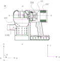
图1为本发明一实施例中吸尘器的结构示意图;1 is a schematic structural diagram of a vacuum cleaner in an embodiment of the present invention;
图2为图1所示的吸尘器的剖面图;Fig. 2 is a sectional view of the vacuum cleaner shown in Fig. 1;
图3为图2所示的吸尘器中去掉除尘件及分离件的剖面图;FIG. 3 is a sectional view of the vacuum cleaner shown in FIG. 2 with the dust removal part and the separation part removed;
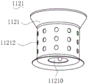
图4为图2所示的吸尘器中除尘件的结构示意图;Fig. 4 is the structural schematic diagram of the dust removal member in the vacuum cleaner shown in Fig. 2;
图5为图2所示的吸尘器中分离件的结构示意图;FIG. 5 is a schematic structural diagram of a separating member in the vacuum cleaner shown in FIG. 2;
图6为图5所示的分离件在另一方向的结构示意图;FIG. 6 is a schematic structural diagram of the separator shown in FIG. 5 in another direction;
图7为图2所示的吸尘器中集尘件的结构示意图;Fig. 7 is the structural schematic diagram of the dust collecting member in the vacuum cleaner shown in Fig. 2;
图8为图2所示的吸尘器中导风壳体的结构示意图;8 is a schematic structural diagram of an air guide housing in the vacuum cleaner shown in FIG. 2;
图9为图2所示的吸尘器中过滤件的结构示意图。FIG. 9 is a schematic structural diagram of the filter element in the vacuum cleaner shown in FIG. 2 .
具体实施方式Detailed ways
为了便于理解本发明,下面将参照相关附图对本发明进行更全面的描述。附图中给出了本发明的较佳的实施例。但是,本发明可以以许多不同的形式来实现,并不限于本文所描述的实施例。相反地,提供这些实施例的目的是使对本发明的公开内容的理解更加透彻全面。In order to facilitate understanding of the present invention, the present invention will be described more fully hereinafter with reference to the related drawings. Preferred embodiments of the invention are shown in the accompanying drawings. However, the present invention may be embodied in many different forms and is not limited to the embodiments described herein. Rather, these embodiments are provided so that a thorough and complete understanding of the present disclosure is provided.
需要说明的是,当元件被称为“固定于”另一个元件,它可以直接在另一个元件上或者也可以存在居中的元件。当一个元件被认为是“连接”另一个元件,它可以是直接连接到另一个元件或者可能同时存在居中元件。本文所使用的术语“垂直的”、“水平的”、“左”、“右”以及类似的表述只是为了说明的目的。It should be noted that when an element is referred to as being "fixed to" another element, it can be directly on the other element or intervening elements may also be present. When an element is referred to as being "connected" to another element, it can be directly connected to the other element or intervening elements may also be present. The terms "vertical," "horizontal," "left," "right," and similar expressions are used herein for illustrative purposes only.
除非另有定义,本文所使用的所有的技术和科学术语与属于本发明的技术领域的技术人员通常理解的含义相同。本文中在本发明的说明书中所使用的术语只是为了描述具体的实施例的目的,不是旨在于限制本发明。本文所使用的术语“及/或”包括一个或多个相关的所列项目的任意的和所有的组合。Unless otherwise defined, all technical and scientific terms used herein have the same meaning as commonly understood by one of ordinary skill in the art to which this invention belongs. The terms used herein in the description of the present invention are for the purpose of describing specific embodiments only, and are not intended to limit the present invention. As used herein, the term "and/or" includes any and all combinations of one or more of the associated listed items.
请一并参阅图1,本发明提供一种吸尘器10。吸尘器10包括过滤装置11、排气装置13、供电装置15及握持部17。供电装置15驱动排气装置13工作,以在过滤装置11内形成负吸压力,以使外部气流进入至过滤装置11内。过滤装置11用于过滤气流中的灰尘及杂质。握持部17用于方便用户握持。在一些实施例中,握持部17为中空结构,握持部17内设置有控制器,控制器与排气装置13及供电装置15电连接,握持部17的外周设置有控制按键170。吸尘器10工作时,按压控制按键170,控制器控制供电装置15驱动排气装置13工作。吸尘结束后,再次按压控制按键170,吸尘器10停止工作。Please also refer to FIG. 1 , the present invention provides a
排气装置13及供电装置15相对且间隔设置于过滤装置11相对的两端,且排气装置13与过滤装置11之间能够进行气流交换。握持部17连接于排气装置13及供电装置15之间。以握持部17的轴线为基准,握持部17轴线的两端分别穿过供电装置15及排气装置13。The
具体地,在吸尘器10中,排气装置13及供电装置15为吸尘器10的主要重量部件,握持部17连接于排气装置13及供电装置15之间,因此,吸尘器10的重量可较为均匀的分布于握持部17的两端,使得吸尘器10的重心较为接近握持部17。而以握持部17的轴线为基准,轴线的两端分别穿过供电装置15及排气装置13。故吸尘器10的重量还可较为均匀的分布于握持部17的两侧,使得吸尘器10的重心更为接近握持部17。因此,吸尘器10在握持时更省力,可方便握持。Specifically, in the
而握持部17连接于排气装置13及供电装置15之间时,在一些实施例中,握持部17相对排气装置13及供电装置15倾斜设置,握持部17连接于供电装置15的一端到过滤装置11的距离大于握持部17连接于排气装置13的一端到过滤装置11的距离。即握持部17连接排气装置13的一端相对握持部17连接供电装置15的一端更靠近过滤装置11。该种设计符合人体工学的设置,可方便用户握持,且在握持时更省力。When the gripping
在另一些实施例中,握持部17也可垂直排气装置13及供电装置15设置。In other embodiments, the holding
请一并参阅图2及图3,过滤装置11包括壳体110及容置于壳体110内的过滤组件112。具体地,壳体110具有壳体内腔1101,过滤组件112容置于壳体内腔1101。排气装置13包括具有排气腔1301的排气外壳130、排气件132以及为排气件132提供电驱动的动力组件134,排气件132及动力组件134均收容于排气腔1301内。供电装置15包括具有供电腔152的供电外壳150以及容置于供电腔152内的供电组件154。排气外壳130以及供电外壳150分别连接于壳体110相对的两端,且位于壳体110的同一侧,以拼接形成整个吸尘器10的机壳。具体地,壳体110、排气外壳130以及供电外壳150可一体成型或分开成型。Please refer to FIG. 2 and FIG. 3 together. The
在吸尘器10中,供电外壳150一般设置于整个吸尘器10的底部,排气外壳130相对供电外壳150间隔设置,位于整个吸尘器10的顶部。壳体110位于吸尘器10的左侧,按照用户一般为右手操作的原则,握持部17一般位于吸尘器10的右侧。In the
壳体110的外壁开设有与壳体内腔1101连通的进气口1102,进气管114配接于进气口1102,并与进气口1102连通形成进气通道1141。排气外壳130的排气腔1301与壳体110的壳体内腔1101连通,且排气外壳130上开设有排气腔1301连通的排气口1303。供电腔152与除尘腔及排气腔1301之间隔离并独立。因此,可使得收容于供电腔152内的供电组件154与外部的水汽及灰尘隔离,以便于维持供电组件154的正常工作。此外,当供电组件154设置于供电腔152内时,可使得整个供电装置15的重量较大。因此,供电装置15可以作为整个吸尘器10的支撑主体来使用。在吸尘器10未使用时,操作供电装置15与安装面(例如地面、桌面等)接触,使得整个吸尘器10可稳定地安装于安装面。The outer wall of the
在一些实施例中,排气外壳130与供电外壳150为平行设置,且排气外壳130及供电外壳150均与壳体110垂直设置,因此,整个吸尘器10的外观较为规整,且更为美观。在本具体实施例中,壳体110为竖直设置,排气外壳130与供电外壳150均为水平设置。(本发明中提及的水平、竖直等方位均以吸尘器10在图1所示的水平、竖直为参照标准,即吸尘器10正常放置于水平面时的状态)。In some embodiments, the
在其他一些实施例中,排气壳体110与供电外壳150之间也可倾斜设置。In some other embodiments, the
动力组件134与供电组件154电连接,且动力组件134在供电组件154的驱动下于壳体内腔1101及排气腔1301内形成负压吸力,以使外界环境中的空气形成气流进入壳体内腔1101,并从壳体内腔1101经过滤组件112后流入至排气腔1301。过滤组件112用于过滤带有灰尘与杂物的气流,且过滤后的灰尘及杂物收集于壳体内腔1101。排气件132用于在气流从排气口1303排出前再次对气流进行过滤,并将过滤后的清洁气流重新排入外界环境。The
动力组件134位于过滤组件112与排气件132之间。The
即动力组件134相较于排气件132更接近过滤组件112。因此,经过滤组件112过滤后的气流流动至动力组件134的路径更短。较短的路径使得气流在流动至动力组件134的过程中风损较小,动量衰减程度较小。进而,气流仍可以较快的速度流向排气件132,并经过排气件132的过滤后从排气口1303排出至外界环境。气流的流动速度较快,可加速吸尘器10内的气流与外部的交换速度,从而可有效提高整个吸尘器10的工作效率。That is, the
进一步地,动力组件134的进风端配接于过滤组件112的出风端。Further, the air inlet end of the
动力组件134的进风端配接于过滤组件112的出风端,可进一步缩短过滤组件112与动力组件134之间的气流流动路径,使得气流的风损更小,吸尘器10的工作效率可进一步提高。具体地,动力组件134的进风端配接于过滤组件112的出风端,可以理解为动力组件134位于过滤组件112外部,且动力组件134的进风端端面与过滤组件112的出风端端面抵接,使得动力组件134与过滤组件112仅在动力组件134进风端的端面以及过滤组件112的出风端端面处发生重合。或者,也可以动力组件134的进风端及过滤组件112的出风端套接,使得动力组件134与过滤组件112具有更多的重合部分。具体地,动力组件134的进风端与过滤组件112的出风端套接可以理解为动力组件134的进风端经过滤组件112的出风端端口伸入至过滤组件112内,或者过滤组件112的出风端经动力组件134的进风端端口伸入至动力组件134内。The air inlet end of the
更进一步地,过滤组件112的出风端与动力组件134的进风端套接。Furthermore, the air outlet end of the
因此,过滤组件112的出风端流出的气流可直接进入至动力组件134内,使得过滤组件112与动力组件134之间气流流动的路径最短,气流具有最小的风损,整个吸尘器10具有较高的工作效率。Therefore, the air flow from the air outlet end of the
动力组件134的轴线(b-b)穿过过滤组件112的出风端及动力组件134的进风端,过滤组件112的轴线(a-a)与动力组件134的轴线呈夹角设置,且夹角(∠β)小于等于90度。The axis (b-b) of the
具体地,过滤组件112进气端的进气方向(如图2箭头c所示)与过滤组件112轴线(a-a)的延伸方向(Y方向)垂直。在动力组件134的作用下,过滤组件112出气端的出气方向(如图2箭头d所示)及动力组件134进气端的进气方向(如图2箭头d所示)与动力组件134的轴线(b-b)的延伸方向(X方向)相同。过滤组件112内气流在进气端及出气端之间的气流方向(如图2箭头e所示)与过滤组件112轴线(a-a)的延伸方向(Y方向)相同。过滤组件112的轴线(a-a)与动力组件134的轴线(b-b)之间的夹角可以理解为过滤组件112在进气端与出气端的气流方向与过滤组件112出气端的出气方向之间的夹角(∠β),或者,也可以理解为过滤组件112在进气端与出气端的气流方向与动力组件134进气端的进气方向之间的夹角(∠β)。通过设置过滤组件112的轴线(a-a)与动力组件134(b-b)的轴线呈夹角(∠β)设置,且夹角(∠β)小于等于90度,气流流经过滤组件112后仅需转过较小的角度便可进入至动力组件134的进气端内,因而能够有效降低气流的转向风阻,使得气流仍保持较快的流速,以便于提高吸尘器10的工作效率。Specifically, the intake direction of the intake end of the filter assembly 112 (as shown by arrow c in FIG. 2 ) is perpendicular to the extension direction (Y direction) of the axis (a-a) of the
动力组件134与排气件132沿动力组件134的轴线方向间隔设置。The
一般地,动力组件134在工作的过程中会产生声波,且声波是通过气流的流动进行传播的。在本申请中,通过设置动力组件134与排气件132为间隔设置,因此,声波在排气腔1301内的传播路径增长,声波与排气外壳130内壁的接触频率将增加。声波不断与排气腔1301的内壁发生碰撞,导致声波的动量大幅衰减,声波的分贝数减弱。进而,从排气口1303处排出的声波噪音较小,吸尘器10的用户体验感也随之提升。Generally, the
需要说明的是,在其他一些实施例中,动力组件134与排气件132也可相抵接。It should be noted that, in some other embodiments, the
请再次参阅图2,过滤组件112包括配接于壳体内腔1101中的除尘件1121、分离件1123及过滤件1125。除尘件1121、分离件1123及过滤件1125沿过滤组件112的轴线方向,从壳体内腔1101的底部至顶部的方向依次布设,分离件1123连通于除尘件1121与过滤件1125之间。外部气流依次流经进气通道1141,除尘件1121及分离件1123,而由分离件1123分离产生的气流进入至过滤件1125内,并从过滤组件11的出气端流入至动力组件134内。除尘件1121、分离件1123及过滤件1125均可对气体进行气尘分离。。Referring to FIG. 2 again, the
请同时参阅图4、图5及图9,除尘件1121为筒状的过滤网。除尘件1121中空形成除尘腔11210,除尘件1121的侧壁开设有除尘孔11212,分离件1123上开设有分离通道11230,除尘孔11212、除尘腔11210及分离通道11230依次连通。具体地,除尘腔11210是指过滤网围设形成的空间,该空间属于壳体内腔1101的一部分。过滤件1125包括过滤主体11250及设置于过滤主体11250外周的至少两条挡风墙11252,过滤主体11250中空形成收集腔11253,至少两条挡风墙11252沿过滤主体11250周向设置,且将过滤主体11250的外周分隔形成相互独立的进风区域11254及出风区域11255。气流经进风区域11254一次过滤后再次经出风区域11255二次过滤,并由排气装置13排出。Please refer to FIG. 4 , FIG. 5 and FIG. 9 at the same time, the
下面通过具体的描述对气流流入并流出壳体内腔1101的具体流动路径进行解释说明。请同时参阅3及图6,从进气通道1141进入至壳体内腔1101中的气流在动力组件134的作用下,依次通过除尘孔11212、除尘腔11210及分离通道11230。继而,由分离件1123的分离通道11230分离产生的气流从进风区域11254进入收集腔11253内,而后经过出风区域11255流入至动力组件134的进气端。在气流流经除尘孔11212时,粒径较大的灰尘及杂物与气流分离,并收集于壳体内腔1101的底部。继而,气流从除尘腔11210内沿朝向壳体内腔1101顶部的方向流入至分离通道11230。具体地,分离件1123为旋风分离器,分离通道11230由锥状结构的内壁围设形成。锥形结构的侧壁开设有入气口11232,气流从入气口11232处流入至分离通道11230,并在分离通道11230内对气流及粒径较小的灰尘及杂质进行分离。The specific flow paths of the airflow flowing into and out of the
请同时参阅图7,过滤组件112还包括集尘件1127,集尘件1127穿设于除尘腔11210。集尘件1127相对的两端分别与壳体内腔1101的底部及锥形结构朝向壳体内腔1101底部的一端抵接,以支撑分离件1123,并可进行自身的定位。除尘件1121朝向分离件1123的一端开设有集尘孔11270,集尘件1127内部形成有集尘腔11272,集尘孔11270与分离通道11230朝向壳体内腔1101底部的开口对齐并连通。因此,从分离通道11230内分离出的粒径较小的灰尘及杂物可从集尘孔11270处收集于集尘腔11272内。经分离通道11230分离的气流继续流动,并依次流经进风区域11254、收集腔11253及出风区域11255,而后流入至动力组件134的进气端,在经过排气件132后从排气口1303排出。进风区域11254及出风区域11255分别对气流进行一次过滤及二次过滤,在进风区域11254处分离的灰尘及杂物可掉落至分离件1123上,或者收集于壳体内腔1101的底部等等。在出分区域分离的灰尘及杂物可收集于收集腔11253内。相较于传统的过滤件1125而言,本申请中的过滤件1125可对气流进行两次过滤,因而使得吸尘器10及其过滤装置11具有较佳的气尘分离效果。而挡风墙11252的设置,可防止流经进风区域11254与出风区域11255的气流窜流,使得气流在流经过滤件1125时必须经过进风区域11254后,才可流经出风区域11255,以保证吸尘器10及过滤装置11具有较佳的气尘分离效果。Please also refer to FIG. 7 , the
请同时参阅图8及图9,壳体110包括导风壳体110,过滤装置11包括导风管116,导风壳体110呈开放环形结构并在尾端形成开口,导风管116密封配接于开口,并与过滤主体11250上的出风区域11255对应连通。排气装置13的动力组件134与导风管116远离出风区域11255的一端配接。导风壳体110环设于进风区域11254的过滤主体11250外,且两者之间间隔形成一个导流腔11041。导风壳体110上开设有导风孔11043,位于进风区域11254的过滤主体11250上开设有一次过滤孔11256,导风孔11043、导流腔11041以及一次过滤孔11256共同连通形成一条进风通道。位于出风区域11255的过滤主体11250上开设有二次过滤孔11257,二次过滤孔11257及导风管116共同连通形成一条出风通道。Please refer to FIG. 8 and FIG. 9 at the same time, the
具体地,壳体110还包括主壳体1103,在一些实施例中,主壳体1103内形成有壳体内腔1101,导风壳体110配接于主壳体1103内,并将壳体内腔1101分隔形成导流腔11041、分离腔1103及过滤件1125的空间。在另一些实施例中,主壳体1103也可以与导风壳体110相互对接形成整个壳体110结构,主壳体1103内形成有分离腔1103,导风壳体110为双层结构,导风壳体110内形成有导流腔11041及过滤件1125的空间。导流腔11041、分离腔1103及设置过滤件1125的空间总共构造形成壳体内腔1101。除尘件1121及分离件1123位于分离腔1103内,且分离件1123上的分离通道11230远离集尘件1127的开口与导风孔11043连通。从分离通道11230分离出的气流依次通过导风孔11043、导流腔11041、一次过滤孔11256、收集腔11253、二次过滤孔11257及导风管116进入至动力组件134的进气端。具体地,导风管116远离二次过滤孔11257的一端即为过滤组件112的出风端。Specifically, the
通过设置导风壳体110,一方面,导风壳体110与进风区域11254共同形成的进风通道可对气流进行导向,以保证从分离件1123内流出的气流可在进风通道的作用下导入至进风区域11254。相较于气流在壳体内腔1101中四处扩散而言,进风通道的设置使得气流可集中进入至进风区域11254,从而便于提升吸尘器10的工作效率。另一方面,气流在流经过滤主体11250的一次过滤孔11256时,被分离的粒径更小的灰尘及杂质可收集于导流腔11041内,以防止灰尘及杂质扩散而影响吸尘器10的除尘效果。By arranging the
进一步地,一次过滤孔11256的孔径大于二次过滤孔11257的孔径。Further, the pore size of the
相较于一次过滤孔11256与二次过滤孔11257的孔径相等而言,通过设置一次过滤孔11256的孔径大于二次过滤孔11257的孔径,使得过滤件1125可对不同粒径的灰尘及杂质进而过滤,使得吸尘器10具有更好的气尘分离效果。Compared with the pore size of the
导风壳体110上开设有安装孔11044,过滤件1125通过安装孔11044可拆卸地装配于导风壳体110内,且收集腔11253与导流腔11041连通。The
因此,可方便过滤件1125的装卸。当收集腔11253内积满灰尘及杂物时,可从安装孔11044处将过滤件1125从吸尘器10中取出,并将过滤件1125清洁后重新放入至导风壳体110内使用,以防止灰尘堵塞一次过滤孔11256及二次过滤孔11257而造成过滤件1125较差的过滤效果。具体地,安装孔11044可开设于导风壳体110的侧壁、顶壁或者底壁等等。在本具体实施例中,安装孔11044开设于导风壳体110的顶壁,过滤件1125的一端设置有与收集腔11253连通的开口,且过滤件1125的开口与安装孔11044位置对齐,则过滤件1125安装于导风壳体110内时,过滤件1125内的灰尘及杂质可在重力的作用下收集于收集腔11253的底部。Therefore, the attachment and detachment of the
为方便对过滤件1125进行装卸,还可在过滤件1125的开口边缘设置提手11258,以方便用户握持于提手11258处操作过滤件1125安装或拆卸。In order to facilitate the mounting and dismounting of the
值得一提的是,若壳体110为由导风壳体110配接于主壳体1103内形成,则可在主壳体1103的顶端开设装配口,盖体覆盖于装配口处。当拆卸盖体时,可从装配口处对除尘件1121、集尘件1127、分离件1123、导风壳体110、过滤件1125及导风管116进行拆卸或安装,这样,可提升吸尘器10装配的简便性。若主壳体1103与导风壳体110相互对接形成整个壳体110,则可在安装孔11044处设置盖体,打开盖体即可对过滤件1125进行装配,盖上盖体还可防止收集于收集腔11253内的灰尘及杂质吹散至外界环境中,使得吸尘器10装配简单且具有较佳的集尘效果。It is worth mentioning that if the
进一步地,安装孔11044为阶梯孔,过滤主体11250的外缘形成有搭接边11259,搭接边11259搭设于阶梯孔的孔壁上。Further, the
具体地,搭接边11259可在重力的作用下搭设于阶梯孔的孔壁上,首先,可对整个过滤件1125进行支撑及固定,使得过滤件1125的安装更简单且更稳定。因此,可防止过滤件1125相对壳体110晃动而导致导流腔11041无法与进风区域11254对齐,出风区域11255无法与导气管对齐而影响过滤件1125的过滤效果。其次,搭接边11259的设置还可方便对过滤件1125进行拆卸。Specifically, the overlapping
更进一步地,壳体110包括若干筋肋,导风壳体110包括底壁11045、由底壁11045外缘朝同一方向延伸形成的侧壁11046以及与底壁11045相对的顶壁11047,每根筋肋沿过滤件1125的轴线方向配接于顶壁11047与底壁11045之间,且若干筋肋沿过滤件1125的周向间隔设置,过滤件1125可拆卸地装配于由若干筋肋围合形成的空间内。Further, the
具体地,底壁11045上开设有导风孔11043,安装孔11044开设于顶壁11047,底壁11045、顶壁11047及侧壁11046共同围设形成导流腔11041,导风孔11043连通于分离件1123的分离通道11230与导流腔11041之间。因此,导风孔11043内的气流可在导风孔11043的作用下沿动力组件134的驱动方向进入至导流腔11041内。在一些实施例中,顶壁11047及侧壁11046在底壁11045上的投影可部分覆盖底壁11045。在该实施例中,过滤件1125在安装于导风壳体110内时,过滤件1125背向安装孔11044的表面可与底壁11045贴合,使得过滤件1125可稳定地支撑于底壁11045上。或者,在其他一些实施例中,顶壁11047及侧壁11046在底壁11045上的投影可完全覆盖底壁11045。在该实施例中,在底壁11045与安装孔11044相对的位置开设有避位孔,过滤件1125在安装于导风壳体110内时,过滤件1125穿设于避位孔及安装孔11044内。Specifically, the
而通过设置多根筋肋1104,多根筋肋1104对过滤件1125的安装具有限位作用,过滤件1125可稳定地固定于筋肋1104围合形成的空间内,以防止过滤件1125在工作过程中晃动而导致导流腔11041无法与进风区域11254对准,出风区域11255无法与导风管116对齐而造成过滤件1125较差的过滤效果。具体地,在此处的空间仅为过滤件1125的安装区域,该空间不属于导流腔11041的一部分。该空间与导流腔11041及分离腔1103共同构成壳体内腔1101。And by providing a plurality of
进一步地,若干筋肋1104沿过滤件1125周向间隔设置于进风区域11254外,每根筋肋1104与进风区域11254的过滤主体11250的外表面贴合,且每相邻的两根筋肋1104将对应的进风区域11254分隔形成一个子进风区域11254。Further, a plurality of
具体地,每相邻的两根筋肋1104可对导流腔11041内的气流进行导流,使得与每个子进风区域11254对应的导流腔11041内的气流可从对应的子进风区域11254流入至收集腔11253内。因此,气流在通过进风区域11254时更加有序且较为均为,这不仅使得气流可较快的通过进风区域11254,以便于提高吸尘器10的工作效率,而且,每个子进风区域11254均可对气流进行过滤,还可提升吸尘器10的过滤效果。Specifically, every two
上述吸尘器10,排气装置13及供电装置15为吸尘器10的主要重量部件,由于握持部17连接于排气装置13及所述供电装置15之间,因此,吸尘器10的重量可较为均匀的分布于握持部17的两端,使得吸尘器10的重心较为接近握持部17。与此同时,以握持部17的轴线为基准,轴线的两端分别穿过供电装置15及排气装置13,故吸尘器10的重量还可较为均匀的分布于握持部17的两侧,使得吸尘器10的重心更为接近握持部17。因此,吸尘器10在握持时更省力,可方便握持。The above-mentioned
以上所述实施例的各技术特征可以进行任意的组合,为使描述简洁,未对上述实施例中的各个技术特征所有可能的组合都进行描述,然而,只要这些技术特征的组合不存在矛盾,都应当认为是本说明书记载的范围。The technical features of the above-described embodiments can be combined arbitrarily. For the sake of brevity, all possible combinations of the technical features in the above-described embodiments are not described. However, as long as there is no contradiction between the combinations of these technical features, All should be regarded as the scope described in this specification.
以上所述实施例仅表达了本发明的几种实施方式,其描述较为具体和详细,但并不能因此而理解为对发明专利范围的限制。应当指出的是,对于本领域的普通技术人员来说,在不脱离本发明构思的前提下,还可以做出若干变形和改进,这些都属于本发明的保护范围。因此,本发明专利的保护范围应以所附权利要求为准。The above-mentioned embodiments only represent several embodiments of the present invention, and the descriptions thereof are specific and detailed, but should not be construed as a limitation on the scope of the invention patent. It should be pointed out that for those of ordinary skill in the art, without departing from the concept of the present invention, several modifications and improvements can also be made, which all belong to the protection scope of the present invention. Therefore, the protection scope of the patent of the present invention should be subject to the appended claims.
Claims (12)
Priority Applications (1)
| Application Number | Priority Date | Filing Date | Title |
|---|---|---|---|
| CN201911165198.8A CN110876580A (en) | 2019-11-25 | 2019-11-25 | Vacuum cleaner |
Applications Claiming Priority (1)
| Application Number | Priority Date | Filing Date | Title |
|---|---|---|---|
| CN201911165198.8A CN110876580A (en) | 2019-11-25 | 2019-11-25 | Vacuum cleaner |
Publications (1)
| Publication Number | Publication Date |
|---|---|
| CN110876580A true CN110876580A (en) | 2020-03-13 |
Family
ID=69730106
Family Applications (1)
| Application Number | Title | Priority Date | Filing Date |
|---|---|---|---|
| CN201911165198.8A Pending CN110876580A (en) | 2019-11-25 | 2019-11-25 | Vacuum cleaner |
Country Status (1)
| Country | Link |
|---|---|
| CN (1) | CN110876580A (en) |
Cited By (3)
| Publication number | Priority date | Publication date | Assignee | Title |
|---|---|---|---|---|
| CN111568295A (en) * | 2020-06-09 | 2020-08-25 | 宁波海际电器有限公司 | A vacuum cleaner core assembly |
| CN111870181A (en) * | 2020-08-27 | 2020-11-03 | 东莞市智美生活电子科技有限公司 | Hand-held vacuum cleaner |
| CN114073441A (en) * | 2020-08-17 | 2022-02-22 | 添可智能科技有限公司 | Dust collector |
Citations (9)
| Publication number | Priority date | Publication date | Assignee | Title |
|---|---|---|---|---|
| CN101489454A (en) * | 2006-07-18 | 2009-07-22 | 戴森技术有限公司 | Hand-held cleaning device |
| CN203953544U (en) * | 2014-05-21 | 2014-11-26 | 深圳市斯珀特思科技有限公司 | Portable vacuum suction cleaner |
| CN205697528U (en) * | 2016-04-28 | 2016-11-23 | 雷国强 | A kind of portable and dust-sucking device |
| CN206687663U (en) * | 2016-11-03 | 2017-12-01 | 江苏美的清洁电器股份有限公司 | Hand-held cleaners |
| CN107744366A (en) * | 2017-11-12 | 2018-03-02 | 炬大科技有限公司 | A kind of dust catcher holds thermomechanical components |
| CN109124461A (en) * | 2017-06-28 | 2019-01-04 | 苏州宝时得电动工具有限公司 | Hand-held cleaners and dust catcher sub-assembly |
| CN109674395A (en) * | 2019-02-28 | 2019-04-26 | 小狗电器互联网科技(北京)股份有限公司 | Filter assemblies and dust catcher |
| CN110477798A (en) * | 2019-09-23 | 2019-11-22 | 小狗电器互联网科技(北京)股份有限公司 | A kind of electric machine assembly of dust catcher, gas deflation assembly, method for exhausting and dust catcher |
| CN211633058U (en) * | 2019-11-25 | 2020-10-09 | 珠海格力电器股份有限公司 | Vacuum cleaner |
-
2019
- 2019-11-25 CN CN201911165198.8A patent/CN110876580A/en active Pending
Patent Citations (9)
| Publication number | Priority date | Publication date | Assignee | Title |
|---|---|---|---|---|
| CN101489454A (en) * | 2006-07-18 | 2009-07-22 | 戴森技术有限公司 | Hand-held cleaning device |
| CN203953544U (en) * | 2014-05-21 | 2014-11-26 | 深圳市斯珀特思科技有限公司 | Portable vacuum suction cleaner |
| CN205697528U (en) * | 2016-04-28 | 2016-11-23 | 雷国强 | A kind of portable and dust-sucking device |
| CN206687663U (en) * | 2016-11-03 | 2017-12-01 | 江苏美的清洁电器股份有限公司 | Hand-held cleaners |
| CN109124461A (en) * | 2017-06-28 | 2019-01-04 | 苏州宝时得电动工具有限公司 | Hand-held cleaners and dust catcher sub-assembly |
| CN107744366A (en) * | 2017-11-12 | 2018-03-02 | 炬大科技有限公司 | A kind of dust catcher holds thermomechanical components |
| CN109674395A (en) * | 2019-02-28 | 2019-04-26 | 小狗电器互联网科技(北京)股份有限公司 | Filter assemblies and dust catcher |
| CN110477798A (en) * | 2019-09-23 | 2019-11-22 | 小狗电器互联网科技(北京)股份有限公司 | A kind of electric machine assembly of dust catcher, gas deflation assembly, method for exhausting and dust catcher |
| CN211633058U (en) * | 2019-11-25 | 2020-10-09 | 珠海格力电器股份有限公司 | Vacuum cleaner |
Cited By (3)
| Publication number | Priority date | Publication date | Assignee | Title |
|---|---|---|---|---|
| CN111568295A (en) * | 2020-06-09 | 2020-08-25 | 宁波海际电器有限公司 | A vacuum cleaner core assembly |
| CN114073441A (en) * | 2020-08-17 | 2022-02-22 | 添可智能科技有限公司 | Dust collector |
| CN111870181A (en) * | 2020-08-27 | 2020-11-03 | 东莞市智美生活电子科技有限公司 | Hand-held vacuum cleaner |
Similar Documents
| Publication | Publication Date | Title |
|---|---|---|
| CN109730581B (en) | Handheld Vacuum Cleaner | |
| CN103169420B (en) | vacuum cleaner | |
| CN211633113U (en) | Dust collection station for robot vacuums | |
| CN110840326B (en) | Dust collection device and dust collection equipment | |
| JP2005081135A (en) | Cyclone separation device and vacuum cleaner provided with the same | |
| JP2013132561A (en) | Separating apparatus | |
| WO2019105142A1 (en) | Dust-air separating device and dust collector therewith | |
| JP2005305111A (en) | Cyclone dust collector and vacuum cleaner using the same | |
| KR20180061357A (en) | Three-stage cyclone dust cup filtration system and vacuum cleaner including this system | |
| CN109674395B (en) | Filtering component and dust collector | |
| GB2418630A (en) | Cyclonic separator with noise reducing feature | |
| CN111358336A (en) | handheld vacuum cleaner | |
| CN211484334U (en) | Dust suction device and dust suction equipment | |
| CN211633058U (en) | Vacuum cleaner | |
| CN209915880U (en) | Dust collecting box and cleaning electric appliance | |
| EP4491076B1 (en) | Filtering assembly, vacuum cleaner and cleaning set | |
| CN211484371U (en) | Dust collector and filtering device thereof | |
| CN209915868U (en) | Dust separator of dust collector | |
| CN110584533A (en) | Cyclone, cyclone separation device and handheld dust collector | |
| CN112842131B (en) | Hand-held vacuum cleaner | |
| CN217852707U (en) | Cyclone separator and surface cleaning device | |
| TWM520349U (en) | Cyclone dust collector | |
| WO2024244116A1 (en) | Filtering assembly, vacuum cleaner and cleaning set | |
| CN110893084B (en) | Vacuum cleaner and filter device thereof | |
| CN206063056U (en) | Hand-held cleaners |
Legal Events
| Date | Code | Title | Description |
|---|---|---|---|
| PB01 | Publication | ||
| PB01 | Publication | ||
| SE01 | Entry into force of request for substantive examination | ||
| SE01 | Entry into force of request for substantive examination | ||
| RJ01 | Rejection of invention patent application after publication |
Application publication date: 20200313 |
|
| RJ01 | Rejection of invention patent application after publication |