For example in the switching power circuit of a high-amperage that is used for controlling high-frequency range, people adopt choke to go to change the AC electrorheological into the DC electric current usually, or go to block from the high fdrequency component of DC electric current or the AC electric current of low frequency.
On the other hand, but the field of application switch power circuit since the major part of electronic equipment be tending towards tendency small-sized and that more and more approach and now be expanded.To be summed to and make the slimming of switching power circuit own for satisfying this, so must make the part dimension of choke and so on of Switching Power Supply little and thin.
For example, for the height with a kind of product is reduced to half inch, then from the franchise viewpoint, require constituting its parts or the height (or length) of element is 10mm or littler.In other words, up to now, such as transformer, this class magnetic parts of choke and so on also fails to satisfy the low clearance requirement, in the occasion of using 10W or bigger electrical power, does not also have this small-sized component especially.
In addition, be the radiation efficiency of intensifier circuit, also require the overall physical size of circuit to approach.
In this case, utilization is can be with ferromagnetic powder molded or form the characteristic of certain required form, and the slim magnetic element such as slim choke comes out.
Yet, because the saturation flux density of ferromagnetic material is compared low with metallicl magnetic material, so find that people do not obtain being made by ferromagnetic material the gratifying miniaturization of product all the time during each choke of under the identical performance situation of contrast, making by different magnetic materials.
In view of this class viewpoint, people's attentiveness has been put into to obtaining the technical of a kind of small-sized choke, the strip that has adopted noncrystalline magnetic alloy with saturation flux density more much higher than ferromagnetic material or crystal magnetic alloy to make in this choke.
For producing this element, the magnetic alloy strip that will have a bandwidth is wound in the toroidal core and the appropriate heat treatment in addition of the hollow central portion of a pre-determined inner diameter.Then magnetic core is placed in the plastic holding device or coating with a resinous coat.So a winding twines part by the predetermined number of turn to its strip and works.
One say in passing, it should be noted that as above said because noncrystalline magnetic alloy and crystallization magnetic alloy have the saturation flux density higher than common ferrite, so and the ferrite comparison might obtain a kind of choke of compact conformation by these materials.
Because the magnetic core of this choke obtains by twining above-mentioned magnetic alloy strip, choke makes lead run through toroidal core and constitutes in the case, so for reducing the width that the magnetic core height just must reduce strip.
Yet the width of magnetic alloy strip reduces to make its utmost point to be difficult to be wound in band.That is to say that because the strip width reduces, the pull resistance of this strip reduces.When strip bears predetermined the stretching when going to twine around the axle center, probably strip is very likely broken.
Moreover the inventor finds: even consider and twine thickness and reduced the thickness of resinous coat or container or reduced the width of strip, also be atomic for the effect of the overall slimming of choke.
In view of above-mentioned task, one object of the present invention is to realize the miniaturization of inductance element such as choke.
Inductance element according to the present invention is made of a magnetic core, and this magnetic core constitutes by magnetic alloy strip (bar) coiled being had along the hollow space of its center line and a lead being run through the magnetic core core.In addition, in this specification " magnetic alloy strip (bar) is meant " a magnetic alloy strip (bar), many magnetic alloy strips (bar) or lamination magnetic alloy thin slice ".
Its relative permeability μ is in 100 to 10000 scope.
Preferably the saturation flux density Bs of this magnetic alloy strip is equal to or greater than 0.6T.
0<BsφO/μφi
2≤10
Equally preferably use Fe-based amorphous matter alloy or iron-based alloy crystalline as the magnetic alloy strip.
" hollow space " is meant the space segment that forms in a central shaft part that is defined by winding magnetic alloy strip or superimposed magnetic alloy thin layer (sheet), comprise also that simultaneously resin and so on is filled in this space segment and makes lead pass the housing of this resin.In addition, the present invention includes the device that a keeper of being made by pottery (spacer) can be inserted into this space segment and lead can be inserted keeper.
In addition, the magnetic alloy strip also can be directly on lead, to be formed with magnetic core among the present invention.In a word, lead is inserted with just much of that in the magnetic alloy strip that twines under the final product state.
In addition, when the magnetic alloy strip is twined facing to lead, at that part of virtual band (dummy tape) that is provided with that begins to twine the magnetic alloy strip.
Attach and say that conductor resistance preferably is equal to or less than 20 μ Ω cm, it is then better to be not more than 2 μ Ω cm.
When making inductance element, the example of noncrystalline magnetic alloy as strip can be described below by the present invention:
M
100-aMa′
Wherein M is that dvielement that at least a Fe of being selected from and Co constitute, and M ' is at least a B of being selected from, that dvielement that SiC and Cr constitute, and a is not less than 4 but to be not more than 40 be the atomic percentage (atomic percentage) of Fe-based amorphous matter magnetic alloy.
In the present invention, Fe-based amorphous matter magnetic alloy is preferable.
More particularly, preferably will be used as the noncrystalline magnetic alloy strip of making in the inductance element process of the present invention by the noncrystalline magnetic alloy that following molecular formula is represented.
Fe
xSi
yBzMw
Wherein M is at least a Co that is selected from, Ni, and Nb, Ta, Mo, W, Zr, Cu, Cr, Mn, AL, P and so on formation group, and x, y, z and W are meant atomic percentage, its value satisfies following relation: 0≤X≤85,5≤y≤15,5≤z≤25 and 0≤w≤10 respectively.
Can regulate required component and required strip shape by the method that is called quenching under the melt (rapidly quenching from the melt) by the amorphous thin band that these alloys are made.Usually also might improve various characteristics by it being not less than the appropriate heat treatment that Curie temperature is not higher than under the crystallization temperature again.
It is for example as follows also can to illustrate ultra micro crystalline state (thin crystalline state) magnetic alloy that is configured for making by the strip of inductance element of the present invention:
(Fe
1-aM
a)
100-a-bM′
xM″
y
M is selected from the element of Co and Ni formation group at least one herein, and M ' is that at least a being selected from constitutes Si, B, Ga, Nb, Mo, Ta, W, Ti, Zr, Cr, the element of Mn and Hf, M " be the element of at least a formation Cu and Al family; and a, x and y satisfy relation respectively: the value of 0≤a≤0.5,0≤x≤50 and 0≤y≤10 (wherein x and y are atomic percentages).
In above-mentioned alloy, particularly the crystallite attitude alloy by following general formula (general type) shown type meets the requirements:
(Fe
1-aM
a)
100-x-y-z-α-βSi
xB
yM′
zAl
αCu
β
M is that at least a being selected from constitutes Co in the formula, and the element of Ni family, M ' are that at least a being selected from constitutes Ca, Nb, Mo, Ta, W, Ti, Zr, Cr, Mn, the element of Hf family.Described a, x, y, z, α and β value satisfy the following relationship formula:
0≤a≤0.5 0≤z≤25
0≤x≤30 0≤α≤10
0≤y≤25 0≤β≤3(0.1≤β≤3 are better)
5≤x+y+z≤40 0.1≤α+β≤10
(x wherein, y, z, α and β are atomic percentages)
Best: the crystal particle diameter of alloy crystalline is for being not more than 100
, more desirablely be not more than 500
The crystal block section of same desirable alloy crystalline is not less than 30%, more desirablely is not less than 50%.
Above-mentioned crystalline alloy thin band can obtain by the appropriate heat treatment that applies under a certain temperature that is not less than crystallization temperature to the strip that obtains as the amorphous alloy band usually.Might improve various magnetic characteristics (for example, magnetic permeability, iron loss or electric current stack) by changing condition of heat treatment equally.
Also might be by will be such as MgO, SiO
2And Sb
2O
5And so on the medium powder be accumulated on the surface, one or both sides on strip surface so that the stack surface various characteristics (for example, magnetic conductance or high frequency iron loss) that improves insulated from each other that strip twines.
The magnetic core of inductance element of the present invention is to produce by twining the strip that so obtains.At first, will there be the strip of preset width and predetermined thickness to be wrapped in the heart parts (core member) that reservation shape is arranged.The cross section of these heart parts can be a garden shape or such as any other polygon of rectangle etc.
When the thickness of strip winding part reaches predetermined extent, just stop the winding operation of strip.Then, stable on heating high viscosity resins band is arranged by use, as polyimides (trade (brand) name of producing by chemical company of Du Pont: Kapton) band or by spot welding in case non-return around (wind-back), is fixed to magnetic core with the winding end of strip.
Then lead is inserted and removed in the magnetic core of heart parts.In the case, since with lead as heart parts, so might be easy to obtain the black box formed by magnetic core and lead.In addition, can save the work of the independent heart parts of dismounting.This makes it might reduce manufacturing cost and component number.
In the present invention, by superimposed annular (troidal) magnetic alloy sheet is bonded to each other or inject resin with it with bonding agent, also can obtain the magnetic core of a hollow space.Such magnetic core also is provided with a hollow space near the center so that lead can run through configuration.
Can enumerate as an example: aluminium, aluminium alloy, copper, copper alloy, what ferroalloy or its surface scribbled antioxidation coating is coated with Sn copper cash or the soft Sn copper cash that is coated with, and is coated with the copper cash of scolder, 42 alloy wires and CP line etc.In above-mentioned example, preferably use plating Sn copper cash with low-resistivity.
Subsidiary saying for lead, can respectively have many leads in identical or different cross section along the configuration of magnetic core center line bunchy ground.In the case, these many leads are (that is, lead is by the coating or the porcelain tube insulation) of insulation each other, and these leads can longitudinally be used as a winding on the sidewall of magnetic core.
Secondly, the magnetic core of lead of such acquisition has been installed through heat-treated (for example, for controlling the magnetic characteristic of relative lead magnetic rate) on it.Subsidiary saying also can be installed lead after the heat treatment.For strip is remained on amorphous state, best heat treatment temperature is not less than Curie temperature and is not higher than crystallization temperature again, and is when strip is remained in the ultramicro-crystal attitude under heat-treat condition, and this temperature is not less than crystallization temperature.The optimum range of this heat treatment cycle is from 30 minutes to 24 hours.Subsidiary saying, in the case, by at the oxidizing gas that uses such as nitrogen (N) or argon (Ar), reducing gas or inert gas be as under the surrounding atmosphere, applies 0 to 60KA/m magnetic field (for example 5KA/m) or apply a power along an invariable direction to magnetic core along the strip Width and implement this heat treatment simultaneously and various characteristics can be transferred to desirable value.
After this, magnetic core is encapsulated in the housing or with resin for example (epoxy resin, alkyd resin or silicones) coating reach insulation, to obtain according to inductance element of the present invention.
In element of the present invention, for the relative permeability μ that obtains good electric current superimposed characteristics magnetic core initial point place of magnetization curve under 100KHz must satisfy following relationship:
100≤μ≤10000
Inductance element of the present invention is used as series reactor, alternating current wires choke, active filter choke, switch converters or noise reduction elements choke or the like.
Now, for obtaining good superimposed characteristics under the choke situation that is used for active filter choke and/or switch converters at series reactor or the choke that is used for alternating current wires, best, the relative permeability μ of magnetic core satisfies relational expression: 100≤μ≤2000
Preferable is by regulating heat treated condition, so that relative permeability μ satisfies the relation of 500≤μ≤2000, then the electric current superimposed characteristics becomes more excellent.
On the other hand, for obtain satisfied anti-acoustic capability under the noise reduction elements situation, preferably the relative permeability μ of magnetic core satisfies relational expression: 5000≤μ≤10000.
Attach and say that it is divided by the resulting value of space permeability μ o with magnetic permeability mu i that relative permeability μ means.
On the other hand, the miniaturization of magnetic element depends primarily on saturation flux and crosses density.That is to say, suppose: relative permeability μ keeps constant in saturation flux density Bs, then provides the following relationship between the volume V of the capacitance E of magnetic element and magnetic core:
E∝(Bs)V/(μ)
For obtaining now extensively and generally to use and have than the more jumbo small-sized magnetic cell of ferrite magnetic material, the saturation flux density of this magnetic alloy strip preferably is not less than 0.6T.
In the present invention, the design magnetic core external diameter φ o(m: rice) and internal diameter φ i(m) time, saturation flux density Bs(T: tesla), φ o φ i, relative permeability, space permeability μ o(4 π * 10
-7H/m) and the maximum current density σ of lead will follow following relational expression and meet the requirements)
Bsφo/μμo≤σφi
2/4
The element that satisfies the above-mentioned relation formula by design can obtain a kind of big capacity and small-sized magnet assembly.
Described relational expression can be transformed into following formula:
Bsφ0/μφi
2≤μ0σ/4
Consider the band spare of realizing this magnetic simultaneously, that is, φ 0, and φ i>0 just draws following condition:
0<Bsφo/μφi
2≤μoσ/4
The inventor finds: for suppressing the heat that this element produces, current density preferably is not more than σ=100/ π * 10
6A/m
2(about 32 * 10
6A/m
2).Therefore, through substitution σ=100/ π * 10
6A/m
2, just obtain the saturation flux amount Bs of magnetic core, relative permeability μ, the external diameter φ o(m of magnetic core) and internal diameter φ i(m) between following relationship:
0<Bsφo/μφi
2≤10
According to the present invention, this element satisfies this relation, that is, and and 0<Bs φ, 0/ μ φ i
2≤ 10, more desirablely satisfy relational expression 0.1≤Bs φ o/ μ φ i
2≤ 10, Bs(T wherein) be the saturation flux density of magnetic core, μ is a relative permeability, φ o(m) be the external diameter of magnetic core and φ (m) is the internal diameter of magnetic core, thus even might obtain to make when small-sized when actual components, it still has the element of less temperature rise.
And the conductor resistance that will be used for the present invention preferably is not more than 20 μ Ω cm, the more desirable 2 μ Ω cm that are not more than.That is,, help suppressing temperature rise if conductor resistance is not more than 20 μ Ω cm.In addition, to be not more than the further advantage of 2 μ Ω cm situations be further to have suppressed temperature rise to conductor resistance.
This inductance element can be encapsulated in the housing of the nonmagnetic substance system such as synthetic resin or aluminium, or in the other type can be by the material sealing of epoxy resin and so on.Arranged outside by giving assembly that is to say by the blade of making such as nonmagnetic substances such as aluminium, is housing under the situation that foliaceous or assembly made by synthetic resin in the profile of assembly, can strengthen heat-radiating properties.
The material that can be used as housing can be the polyamide (nylon) that is called plastics, modified model polyamide (trade (brand) name :) by the ARLEN of Mitsui petrochemical company manufacturing, the PBT(polybutylene terephthalate), the PET(polyethylene terephthalate), PPS(polyphenylene sulfide) and the pp(polypropylene) etc.
In addition, be connected in parallel to each other or be connected in series, just may obtain to have the element of different induction and electric current by inductance element with a plurality of such acquisitions.In the case, can obtain uniform outer appearance and do not change the multipurpose element of element heights,, seal these elements to form the assembly of a single assembly element unit with epoxy resin and so on material for example by after parallel each inductance element of configuration.
Subsidiary one says, also these inductance elements can be encapsulated in the housing that a synthetic resin makes, to form single assembly.Under this assembly element situation, owing to the heat that produces also increases, so thereby the housing profile should be the good inductance assembling parts of outside acquisition heat-radiating properties that foliaceous maybe should be arranged on the nonmagnetic substance of aluminium and so on this assembly.
About connecting the method for a plurality of elements, can be encapsulate connected in advance element or by epoxy sealing they, or connect actual installation these elements on substrate by method with printed wire and so on another way.
With to such as electric capacity, the same manner of different elements such as resistance is handled or used element according to the present invention is possible.Because the no winding of element itself, so be easy to handle and compact in size by element of the present invention.
Now the present invention is described with reference to all accompanying drawings.
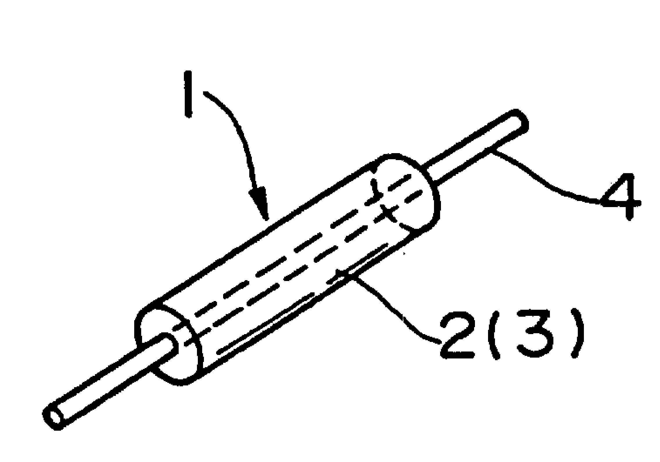
As shown in Figure 1, according to the present invention, the magnetic core 2 that is used for inductance element 1 is made by twining acquired as mentioned above strip 3.At first, will have the strip of preset width and predetermined thickness to be wrapped in is on the heart parts (not shown) that gives the form slection shape.The cross section of these heart parts is not limited to garden shape, and can be rectangle or polygon.
When the thickness of strip winding part reaches predetermined value, the winding operation of constipation bundle strip 3.Processing that the winding end of strip 3 is fixed to magnetic core 2 is to use that (trade (brand) name: Kapton) band waits high viscosity resin band that can be heat-resisting or realizes by spot welding, thereby has prevented to unroll such as polyimides.
Lead 4 is inserted in the magnetic core 2 that takes out heart parts.In the case, as shown in Figure 7, as heart parts, might easily obtain the black box of forming by magnetic core 2 and lead 4 by direct use lead 4.In addition, might save the work of the independent heart parts of dismounting.This makes to reduce manufacturing cost and reduce the component number becomes possibility.
Can enumerate as an example: aluminium, aluminium alloy, copper, copper alloy, ferroalloy or its surface scribble antioxidation coating be coated with the Sn copper cash or through annealing be coated with the Sn copper cash, be coated with the copper cash of scolding tin, 42 alloy wires and CP line etc.Specifically, in above-mentioned example, use plating Sn copper cash to meet the requirements with low-resistivity.
Subsidiary one says, for lead 4, might arrange many bunched conductor 4a that identical or different cross section is respectively arranged along the center line of magnetic core 2.In the case, multiple conducting wires (that is, lead is by coating or porcelain tube insulation) insulated from each other, these leads can be longitudinally on the sidewall of stand-by magnetic core, coiled winding as shown in Figure 9.
Then, make the lead 4 that so obtains has been installed on it magnetic core 2 through heat-treated.Subsidiary one says that it also is possible in heat treatment lead being installed later on.Under heat-treat condition, be in amorphous state for keeping strip, preferably temperature is not less than Curie temperature but is not higher than crystallization temperature, and is when keeping strip to be in the ultra micro crystalline state, and temperature is not less than crystallization temperature.The heat treatment cycle scope is 30 minutes to 24 hours.Subsidiary saying, in the case, by using oxidizing gas, reducing gas or inert gas are as under the surrounding atmosphere, apply 0 to 60KA/m magnetic field (for example 5KA/m) or apply a power to magnetic core along the strip Width, implement this heat treatment simultaneously and various different qualities can be adjusted to desirable value along an invariable direction.
The inductance element 1 that can be encapsulated in the housing that the nonmagnetic substance such as synthetic resin or aluminium makes can be by sealings such as epoxy resin.In the case, as shown in Figure 8, the blade of being made by nonmagnetic substance such as aluminium by the arranged outside of giving assembly promptly, is housing 18 under the situation that foliaceous or assembly made by synthetic resin in the profile of assembly, can strengthen heat-radiating properties.
In addition, by connecting the element that a plurality of inductance elements that obtain like this 1 that are connected in parallel to each other or connect can obtain different induction and electric current.In the case, can obtain uniform outer appearance and do not change the multipurpose element of element heights, for example, by after parallel each inductance element 1 of configuration, seal these elements to form the assembly 5 of a single assembly element unit 6 as shown in Figure 4 with epoxy resin and so on material.
Subsidiary one says, though a plurality of inductance element 1 by resin-sealed among Fig. 4, these inductance elements 1 can be encapsulated in the housing that is made of synthetic resin to form single composition element.Under this composition element situation, because the heat that produces also increases, be the outside that foliaceous maybe should be configured in the nonmagnetic substance such as aluminium assembly so the outward appearance of housing is should be similar shown in Figure 8, thereby obtain the inductor combination unit of heat-radiating properties excellence.
About being used to connect the method for a plurality of elements 1, can encapsulate in advance the element that connects or with epoxy sealing they, or utilize another way by method connection actual installation these elements on substrate with printed wire and so on.
Several instantiation of the present invention and reference examples now are described.
Example 1
As shown in Figure 7, a kind of iron-based non-crystalline magnetic alloy strip 3(trade (brand) name of being made by U.S. Allied-signal company: " Metglas2605S-2 ", composition are Fe
78Si
9B
13(atom %), thickness: 20 μ m, wide: surface 15mm) (side) is coated with Sb
2O
5After this fine powder, is wrapped in this band on the lead 4, and (resistivity: 0.97 μ Ω cm) diameter is that 1.6mm is that the 1.6mm external diameter is 5mm to form internal diameter to the Sn copper cash that is coated with that this is soft, and length is the element 1 of 15mm.
This winding end is fixing by polyimides band (Kapton band).Be exposed under the N atmosphere and heat being not less than Curie temperature and not being higher than under the temperature of crystallization temperature.Specifically, heat-treat condition is 430 ℃ and reaches 2 hours.
Each five element that produce as mentioned above is by parallel arranged and by epoxy resin 5 sealings, and to form an assembly, line end (lead 4) is to stretch out so that can be installed on the printed circuit board (PCB) from assembly one side, produces an assembly element 6 thus.Its outward appearance is shown in Fig. 4.
So that five elements 1 are connected in series in assembly, and the electric current superimposed characteristics of inductance is to record under the 100KHz frequency to these line ends by electric short circuit.
Example 2
As shown in Figure 7, the Fe-based amorphous matter magnetic alloy strip (trade (brand) name: " Metglas 2605S-2 " composition: Fe of making by U.S. Allide-signal company
78Si
9B
13(atom %) thickness: 20 μ m, width: 15ml is on the winding core of 1.6mm around diameter, and after finishing this winding, the end is fixed through spot welding.After this, remove the winding core.So just, obtaining an internal diameter is that 5mm and length are the magnetic core of 15mm for the 1.6mm external diameter.Again it is exposed to N
2Under the atmosphere, and be not less than the temperature heating that Curie temperature is not higher than crystallization temperature again with one.Specifically, heat-treat condition is 430 ℃ and reaches 2 hours.
Be configured as in advance the U-font soft be coated with Sn copper cash (resistivity: 0.89 μ Ω cm) be inserted into this product and be lead 14 by the press reshaping.
This product is encapsulated in by Mitsui Petrochemical company and makes by (the trade (brand) name: in the housing of ARLEN) making 15 of improved polyamide, the adhesive of these housing 15 usefulness epoxy systems (epoxysystem) is fixed to one another, and this outward appearance is shown in Figure 11 and 12.
Reference examples
On the other hand, as a comparison, produce toroidal chokes 11(TM coil 6 μ H-10A as illustrated in Figures 5 and 6) with same nominal capacity.
With with example 1 same way as, (trade (brand) name: " Metglas 2605S-2 ", component is Fe to a kind of Fe-based amorphous matter magnetic alloy strip that will be made by U.S. Allide-signal company
78Si
9B
13, thickness: 20 μ m, wide 5mm) surface (side) around being 21.5mm to external diameter, internal diameter is on the magnetic core 12 of 12.0mm.Make this winding through heat-treated and be placed in the resin-case 15 again.After this will respectively there be two leads 16 of 1.1mm diameter to center on the garden Zhou Fangxiang of this resin system housing 15 side by side around 8 circles.So obtain external diameter (1) is that 27mm and height (h) are the toroidal chokes 11 of 12mm.
To this toroidal chokes, under the 100KHz frequency, measure the electric current superimposed characteristics (reference examples) of its inductance.Figure 10 illustrates between example of the present invention and this reference examples inductance to the variation of superimposed current.Express the contrast on component size between example and the reference examples down.
Therefore, compare with traditional product according to this two example, impression is less, and actual height is about half of conventional products simultaneously.
Do not breaking away under spirit of the present invention and the protection range situation and may make change its various details.In addition, the front only provides for graphic extension the explanation according to the embodiment of the invention, is not for restriction as by the present invention that appended claims defined and the scope of equivalent thereof.