Manual prepreg cutting device
Technical Field
The invention belongs to the field of composite material processing, and relates to a prepreg cutting device for a composite material, in particular to a manual prepreg cutting device.
Background
The maturation of advanced technology in composite materials has made it possible to optimize their performance and to reduce their cost, thus greatly driving the use of composite materials in aircraft. Some large aircraft manufacturers are gradually reducing the proportion of traditional metal working in aircraft design and manufacture, with composite manufacturing being preferred. The automatic filament spreading technology is a full-automatic composite material processing technology developed in the 70 th century by integrating the advantages of two composite material forming technologies of a fiber winding technology and an automatic tape spreading technology. In the automatic filament laying process, prepreg filaments with fixed widths of 3.17mm, 6.35mm or 12.7mm are required. In general, a special automatic slitting device is used to slit prepregs, but in the absence of the slitting device or the slitting capability, it becomes difficult to slit prepregs having a certain width into prepreg filament products having a predetermined size.
Disclosure of Invention
In order to ensure that the production can still normally run under the condition of lacking expensive automatic cutting equipment or lacking cutting capacity, the invention provides a device for manually cutting prepreg, which has the following specific technical scheme:
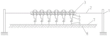
the utility model provides a prepreg device is cut to manual, includes lead screw, knife rest, circular knife blade, steel mould, the knife rest is installed on the lead screw, and is perpendicular with the lead screw, the circular knife blade passes through the bearing connected mode and connects on the knife rest, the steel mould level sets up the below of lead screw is parallel with the lead screw, the circular knife blade perpendicular to the steel mould, the lead screw both ends are connected to on the draw-in groove that can reciprocate through the connecting piece, the draw-in groove is established in support piece.
In the device, when needs cutting preimpregnation material, can lay preimpregnation material on the steel mould, through the connecting piece lapse on the spout, drive the lead screw downwards promptly for the knife rest pushes down, and the blade also then pushes down, removes preimpregnation material, then can carry out the cutting of preimpregnation material. The circular blade is perpendicular to the steel die, so that the cutting linearity can be ensured.
As a further improvement, the method is characterized in that: and a steel plane sacrificial layer is arranged on the upper surface of the steel die.
The steel mould forms horizontal surface, sets up steel plane sacrificial layer on it, can guarantee like this that prepreg can the level place, because the continuous cutting of blade, the life of circular blade can be prolonged in the existence of steel plane sacrificial layer.
As a further improvement, the method is characterized in that: a plurality of tool rests are arranged on the screw rod, and each tool rest is correspondingly provided with a circular blade. The prepreg can be cut into the prepreg meeting the specification at one time according to the specification, so that the cutting efficiency is accelerated.
As a further improvement, the method is characterized in that: and two ends of the tool rest are fixed on the lead screw by screws. In the cutting process, can fix the position of knife rest through the screw for it can not remove in the course of the work, and to a plurality of circular blades during operation together, the horn drunkenness can not appear, also can strictly restrict the position of knife rest according to size specification, makes the cutting more accurate stable.
As a further improvement, the method is characterized in that: the steel plane sacrificial layer is made of a high-molecular soft material. Because the prepreg is laid on the steel plane sacrificial layer, the circular blade can be cut to the steel plane sacrificial layer in the cutting process, and the service life of the circular blade can be prolonged because the steel plane sacrificial layer is made of soft materials.
As a further improvement, the method is characterized in that: the soft material of polymer is rubber or PTFE.
The invention has the beneficial effects that: the device can finish the cutting work of the prepreg under the condition of lacking automatic cutting equipment, and the whole mechanism has the advantages of simple structure, convenient maintenance, wide applicability and convenient use;
in addition, because the two ends of the tool rest are fixed on the screw rod by screws, the prepreg with different specifications and widths can be cut by moving the position of the tool rest, and the application range of the prepreg is expanded.
Drawings
FIG. 1 is a schematic structural diagram of a manual prepreg slitting device in the embodiment;
FIG. 2 is a schematic structural diagram of a tool holder of a manual prepreg slitting device in implementation;
FIG. 3 is a schematic top view of a slitting process of the manual prepreg slitting device in the embodiment;
fig. 4 is a left side sectional view of the support member in the embodiment.
Detailed Description
For the purpose of enhancing the understanding of the present invention, the present invention will be described in further detail with reference to the accompanying drawings and examples, which are provided for the purpose of illustration only and are not intended to limit the scope of the present invention.
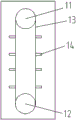
A manual prepreg cutting device is shown in figures 1 and 3 and comprises a screw rod 3, a tool rest 5, a circular blade 6 and a steel die 8, wherein the tool rest 5 is installed on the screw rod 3 and is vertical to the screw rod 3, the circular blade 6 is connected to the tool rest 5 through a bearing connection mode, as shown in figure 2, the circular blade 6 is connected with a blade arm bearing 511, the blade arm bearing 511 is arranged at the lower end of the tool rest 5, the circular blade 6 can roll, the steel die 8 is horizontally arranged below the screw rod 3 and is parallel to the screw rod 3, the circular blade 6 is vertical to the steel die 8, two ends of the screw rod 3 are connected to a chute 14 capable of moving up and down through a connecting piece 2, the chute 14 is arranged in a supporting piece 1, as shown in figure 4 of a left view cross section of the supporting piece 1, a driving wheel 12 and a driven wheel 11 are arranged in the supporting piece 1, a conveying belt 13 is arranged between the driving wheel 12 and the driven wheel 11, the, according to the figure, six knife rests 5 and circular blades 6 are arranged, each knife rest 5 is fixed on a lead screw 3 through screws 4 at two ends, and a steel plane sacrificial layer 7 is made of rubber. The driving wheel 12 can make the conveyor belt 13 displace through manual rotation, and can also control the movement through an external motor.
In the device, the cutting width between two circular blades 6 can be controlled, and is changed through screws 4, so that the prepreg with different specifications and widths can be cut simultaneously, please refer to fig. 3, and the working steps of the device are as follows:
the method comprises the following steps: firstly, installing each component;
step two: the distance between the knife rests 5 is adjusted by screws 4, and the cutting distance is usually 3.175mm, 6.35mm and 12.7mm according to production requirements;
step three: the prepreg 10 is laid on the steel plane sacrificial layer 7, two sides of one end of the steel plane sacrificial layer 7 in the width direction are respectively provided with a limiting block 11, the prepreg 10 is positioned between the two limiting blocks 11, and the steel plane sacrificial layer 7 is tightly attached to the steel die 8;
step four: selecting a slitting initial position and a slitting direction;
step five: rotating the driving wheel 12 by an arc to enable the sliding chute 14 connected with the connecting piece 2 to move downwards, driving the connecting piece 2 downwards at the moment, giving pressure to the circular blade 6 perpendicular to the steel plane sacrificial layer 7, and selecting different downward moving distances according to different prepregs 10 and effect difference after slitting;
step six: along 6 incision directions of circular blade, the manual preimpregnation material 10 that slowly pulls cuts, guarantees by stopper 11 to cut preimpregnation material 10 and follow definite direction parallel translation.
The device has simple structure and lower equipment cost, and can meet the requirements of small-batch production and process test to a certain extent compared with expensive automatic slitting equipment; in addition, when the automatic cutting equipment is damaged, the automatic cutting equipment can be temporarily replaced for use, so that the production can be continuously maintained.