CN110901129B - Full-automatic hydraulic oil press and control method - Google Patents
Full-automatic hydraulic oil press and control method Download PDFInfo
- Publication number
- CN110901129B CN110901129B CN201911179637.0A CN201911179637A CN110901129B CN 110901129 B CN110901129 B CN 110901129B CN 201911179637 A CN201911179637 A CN 201911179637A CN 110901129 B CN110901129 B CN 110901129B
- Authority
- CN
- China
- Prior art keywords
- oil
- valve
- overflow
- hydraulic cylinder
- switching valve
- Prior art date
- Legal status (The legal status is an assumption and is not a legal conclusion. Google has not performed a legal analysis and makes no representation as to the accuracy of the status listed.)
- Active
Links
- 239000010720 hydraulic oil Substances 0.000 title claims abstract description 24
- 238000000034 method Methods 0.000 title claims abstract description 14
- 239000003921 oil Substances 0.000 claims abstract description 121
- 238000007599 discharging Methods 0.000 claims abstract description 36
- 238000003825 pressing Methods 0.000 claims abstract description 18
- 235000013305 food Nutrition 0.000 claims abstract description 14
- 230000009471 action Effects 0.000 claims abstract description 13
- 238000003860 storage Methods 0.000 claims abstract description 12
- 239000000463 material Substances 0.000 claims description 34
- 238000005303 weighing Methods 0.000 claims description 24
- 239000000725 suspension Substances 0.000 claims description 21
- 230000005484 gravity Effects 0.000 claims description 10
- 230000000903 blocking effect Effects 0.000 claims description 3
- 238000009434 installation Methods 0.000 claims description 3
- 239000010410 layer Substances 0.000 claims description 3
- 239000007788 liquid Substances 0.000 claims description 3
- 239000002356 single layer Substances 0.000 claims description 3
- 238000000605 extraction Methods 0.000 claims 1
- 239000000284 extract Substances 0.000 abstract 1
- 238000004519 manufacturing process Methods 0.000 description 8
- 239000002893 slag Substances 0.000 description 7
- 238000012545 processing Methods 0.000 description 4
- 230000008569 process Effects 0.000 description 3
- 238000006243 chemical reaction Methods 0.000 description 2
- 238000004891 communication Methods 0.000 description 2
- 238000010586 diagram Methods 0.000 description 2
- 238000003754 machining Methods 0.000 description 2
- 241000758791 Juglandaceae Species 0.000 description 1
- 229910000831 Steel Inorganic materials 0.000 description 1
- 230000004075 alteration Effects 0.000 description 1
- 230000008859 change Effects 0.000 description 1
- 238000005056 compaction Methods 0.000 description 1
- 230000008602 contraction Effects 0.000 description 1
- 230000000994 depressogenic effect Effects 0.000 description 1
- 238000013461 design Methods 0.000 description 1
- 230000000694 effects Effects 0.000 description 1
- 238000005265 energy consumption Methods 0.000 description 1
- 238000012423 maintenance Methods 0.000 description 1
- 230000007246 mechanism Effects 0.000 description 1
- 238000012986 modification Methods 0.000 description 1
- 230000004048 modification Effects 0.000 description 1
- 238000007789 sealing Methods 0.000 description 1
- 239000013049 sediment Substances 0.000 description 1
- 239000010959 steel Substances 0.000 description 1
- 235000020234 walnut Nutrition 0.000 description 1
Images





Classifications
-
- B—PERFORMING OPERATIONS; TRANSPORTING
- B30—PRESSES
- B30B—PRESSES IN GENERAL
- B30B9/00—Presses specially adapted for particular purposes
- B30B9/02—Presses specially adapted for particular purposes for squeezing-out liquid from liquid-containing material, e.g. juice from fruits, oil from oil-containing material
- B30B9/04—Presses specially adapted for particular purposes for squeezing-out liquid from liquid-containing material, e.g. juice from fruits, oil from oil-containing material using press rams
- B30B9/047—Control arrangements
-
- B—PERFORMING OPERATIONS; TRANSPORTING
- B30—PRESSES
- B30B—PRESSES IN GENERAL
- B30B15/00—Details of, or accessories for, presses; Auxiliary measures in connection with pressing
- B30B15/16—Control arrangements for fluid-driven presses
- B30B15/18—Control arrangements for fluid-driven presses controlling the reciprocating motion of the ram
-
- B—PERFORMING OPERATIONS; TRANSPORTING
- B30—PRESSES
- B30B—PRESSES IN GENERAL
- B30B15/00—Details of, or accessories for, presses; Auxiliary measures in connection with pressing
- B30B15/30—Feeding material to presses
-
- C—CHEMISTRY; METALLURGY
- C11—ANIMAL OR VEGETABLE OILS, FATS, FATTY SUBSTANCES OR WAXES; FATTY ACIDS THEREFROM; DETERGENTS; CANDLES
- C11B—PRODUCING, e.g. BY PRESSING RAW MATERIALS OR BY EXTRACTION FROM WASTE MATERIALS, REFINING OR PRESERVING FATS, FATTY SUBSTANCES, e.g. LANOLIN, FATTY OILS OR WAXES; ESSENTIAL OILS; PERFUMES
- C11B1/00—Production of fats or fatty oils from raw materials
- C11B1/06—Production of fats or fatty oils from raw materials by pressing
Landscapes
- Engineering & Computer Science (AREA)
- Mechanical Engineering (AREA)
- Chemical & Material Sciences (AREA)
- Life Sciences & Earth Sciences (AREA)
- Chemical Kinetics & Catalysis (AREA)
- Oil, Petroleum & Natural Gas (AREA)
- Wood Science & Technology (AREA)
- Organic Chemistry (AREA)
- Fluid-Pressure Circuits (AREA)
- Press Drives And Press Lines (AREA)
Abstract
The invention provides a full-automatic hydraulic oil press and a method, comprising a frame, wherein a main hydraulic cylinder which is vertically installed is arranged in the frame, a charging basket with a through structure is arranged below the main hydraulic cylinder, a pressure head which slides along the inner wall of the charging basket is arranged in the charging basket, the pressure head is connected with the main hydraulic cylinder, an oil receiving disc is arranged at the bottom of the charging basket, a lifting hydraulic cylinder is fixedly arranged on the frame and is connected with the charging basket through a hanging rod so as to lift the charging basket after oil pressing is finished, and cake pressing is convenient to take out; connect food tray and base spout sliding connection, the base spout with connect to be equipped with the driving cylinder of unloading between the food tray, the driving cylinder of unloading is used for the drive to connect the food tray to slide along the base spout and unloads out and press the cake. The invention automatically controls the prepressing and oil pressing actions of the pressure head and switches the automatic discharging action by the combination of the electromagnetic valve and the overflow valve. Through the promotion pneumatic cylinder that sets up, can accomplish the operation back that extracts oil, promote the pneumatic cylinder with the storage bucket, be convenient for take out through automatic discharge's mode and press the cake.
Description
Technical Field
The invention relates to the field of oil press manufacturing, in particular to an automatic full-automatic hydraulic oil press and a control method.
Background
Currently, most vertical hydraulic oil presses on the market are small-sized and manual, and there are relatively few fully automatic vertical hydraulic oil presses, such as a vertical high-efficiency oil press described in chinese patent document CN 207657241U and a hydraulic vertical oil press described in CN 102649320B. But the existing oil press is not convenient for taking out pressed cakes, and the labor intensity is higher. However, when the conventional oil presses are used for pressing oil on materials with high hardness, such as walnuts, the problem that the strength of the press barrel using the side wall oil discharge is reduced due to the oil discharge holes is solved, and the press barrel is easily deformed when the pressure is too high. And the strength of the squeezing barrel is improved only by increasing the thickness, and the processing difficulty of the oil outlet hole of the squeezing barrel is increased. The existing hydraulic control usually adopts manual control, and the operation of workers is easy to make mistakes, and a scheme that a disc type hydraulic vertical oil press of Chinese patent document CN203063145U adopts a high-low pressure overflow combination valve and a manual reversing valve realizes automatic control, but the high-low pressure overflow combination valve in the scheme is an unusual device, and the corresponding hydraulic control chart is not recorded in the document, so that the scheme is difficult to realize.
Disclosure of Invention
The technical problem to be solved by the invention is to provide a full-automatic hydraulic oil press and a method, which can realize full-automatic oil pressing, and in a preferred scheme, can also realize automatic feeding and discharging.
In order to solve the technical problems, the technical scheme adopted by the invention is as follows: a full-automatic hydraulic oil press comprises a rack, wherein a main hydraulic cylinder is vertically installed in the rack, a charging basket with a through structure is arranged below the main hydraulic cylinder, a pressure head sliding along the inner wall of the charging basket is arranged in the charging basket, the pressure head is connected with the main hydraulic cylinder, an oil receiving disc is arranged at the bottom of the charging basket, a lifting hydraulic cylinder is fixedly arranged on the rack and connected with the charging basket through a hanging rod, so that the charging basket is lifted after oil pressing is finished, and cake pressing is convenient to take out;
connect food tray and base spout sliding connection, the base spout with connect to be equipped with the driving cylinder of unloading between the food tray, the driving cylinder of unloading is used for the drive to connect the food tray to slide along the base spout and unloads out and press the cake.
In the preferred scheme, the base spout will connect the both sides of food tray spacing, the one end of the driving cylinder of unloading with connect the food tray articulated, the other end is articulated with the base spout, after the piston rod of the driving cylinder of unloading stretches out completely, the focus that connects the food tray is located outside the end of base spout, connect the food tray to unload at the rotatory angle of action of gravity down, after the piston rod of the driving cylinder of unloading retracts completely, connect the food tray to drop on the base spout under the action of gravity and slide and reset.
In the preferred scheme, the frame is of a portal structure, and the cylinder body of the main hydraulic cylinder is connected with the lower part of the top of the frame;
a piston rod of the main hydraulic cylinder is connected with the pressure head;
an oil passing hole for oil outlet is formed in the side wall of the charging bucket;
an edge for blocking oil is arranged around the oil receiving disc, an opening for discharging oil is arranged on the edge, and the charging bucket is movably arranged on the oil receiving disc;
the lifting hydraulic cylinder is arranged above the top of the rack, the lifting hydraulic cylinder is connected with the middle of the suspension arm, two ends of the suspension arm are connected with the suspension rod, and the suspension rod penetrates through the top of the rack and is connected with the charging bucket.
In a preferable scheme, a weighing hopper is further arranged on one side of the rack, a rotary material opening is formed in the bottom of the weighing hopper and connected with a rotary feeding chute, and a feeding chute driving cylinder is arranged between the weighing hopper and the rotary feeding chute, so that the rotary feeding chute can be moved to the top of the charging bucket or moved away from the top of the charging bucket;
the bottom of the weighing hopper is also provided with a flashboard, and a flashboard driving cylinder is connected with the flashboard to drive the flashboard to open and close.
In the preferred scheme, the charging barrel is at least of a double-layer structure, the outer charging barrel is movably connected with the inner charging barrel, an oil passing hole is formed in one section of the wall, close to the bottom, of the inner charging barrel, and a plurality of communicating grooves which mutually connect the oil passing holes are formed in the outer wall of the inner charging barrel.
In an optional scheme, or the charging bucket is of a single-layer structure, an oil passing hole is formed in a section of wall, close to the bottom, of the charging bucket, the diameter of one end, close to the inner wall of the charging bucket, of the oil passing hole is smaller, and the diameter of one end, close to the outer wall of the charging bucket, of the oil passing hole is larger.
In the preferred scheme, a hydraulic station is further arranged, a hydraulic pump of the hydraulic station is connected with a first switching valve, and the first switching valve is respectively connected with a first reversing valve and a second reversing valve through pipelines;
the second reversing valve is connected with a cavity for lifting of the lifting hydraulic cylinder through a pipeline, the second reversing valve is provided with a pipeline for overflowing, and a second overflow valve is arranged on the pipeline for overflowing;
the first reversing valve is respectively connected with the two end cavities of the main hydraulic cylinder through two pipelines, and the first reversing valve is provided with a pipeline for returning oil;
and a first overflow valve is arranged at the outlet of the hydraulic pump.
In a preferred scheme, a squeezing pipeline between the first reversing valve and the main hydraulic cylinder is also connected with an overflow pipeline, and a second switching valve and a third overflow valve are sequentially arranged on the overflow pipeline along an overflow path;
two positions of the second switching valve are a cut-off position and a conducting position respectively;
the relief pressure of the third relief valve is smaller than that of the first relief valve.
In the preferred scheme, overflow ports of the first overflow valve, the second overflow valve and the third overflow valve are provided with flow sensors, and the flow sensors are connected with the PLC;
the flow sensor is used for detecting whether liquid flow exists at the overflow port.
In a preferred scheme, one oil discharge pipeline of the first switching valve is also connected with a third switching valve, two positions of the third switching valve are a cut-off position and a conduction position respectively, and the third switching valve is connected with a third reversing valve, a fourth reversing valve and a fifth reversing valve;
the third reversing valve is connected with the discharging driving cylinder through two pipelines, the fourth reversing valve is connected with the feeding chute driving cylinder through two pipelines, the fifth reversing valve is connected with the flashboard driving cylinder through two pipelines,
the third reversing valve, the fourth reversing valve and the fifth reversing valve are provided with oil return pipes.
An automatic control method adopting the full-automatic hydraulic oil press comprises the following steps:
s1, when squeezing, the first switching valve is controlled to supply oil to the first switching valve, the second switching valve is conducted, and the pressure head of the main hydraulic cylinder is pressed down;
s2, until the third overflow valve overflows, the third flow sensor collects overflow signals to close the second switching valve, and the pressure head of the main hydraulic cylinder continues to press down;
s3, until the first overflow valve overflows, the second flow sensor collects overflow signals to enable the first reversing valve to reverse, and the pressure head of the main hydraulic cylinder rises;
s4, the first switching valve switches to supply oil to the second switching valve, so that the lifting hydraulic cylinder lifts the charging basket until the second overflow valve overflows, the first flow sensor collects overflow signals and controls automatic or manual discharging;
through the steps, full-automatic oil pressing is realized.
According to the full-automatic hydraulic oil press and the method, the lifting hydraulic cylinder is arranged, so that after oil pressing operation is completed, the charging basket is lifted by the lifting hydraulic cylinder, pressed cakes are left on the oil receiving disc, the pressed cakes are conveniently taken out in an automatic discharging mode, and the taken-out pressed cakes automatically fall on the slag cake conveying belt and are stored in a centralized mode. In the preferred scheme, through adopting double-deck storage bucket to the outer wall at inner storage bucket sets up the structure of intercommunication groove, wherein outer storage bucket can provide sufficient intensity and support, and inner storage bucket then is convenient for filter the material sediment, because inner storage bucket can adopt thinner thickness, has also reduced the processing degree of difficulty of passing the oilhole moreover. The structure of the weighing hopper and the rotary feeding chute realizes accurate automatic feeding and greatly reduces manual intervention. Give the overflow pipeline that squeezes the pipeline additional setting, automatic pre-compaction is realized to the pressure of switching master cylinder output that can be convenient to automatic switch to normal operating pressure, adopt flow sensor to gather overflow signal's scheme, can only realize the automatic control to master cylinder output pressure promptly through adjustment overflow pressure, reduce the control point by a wide margin, improve entire system's stability. The first switching valve can be conveniently switched between working pressure and control pressure, and the safety of the hydraulic system is further improved. The full-automatic hydraulic oil press and the method can realize automatic oil pressing production, greatly reduce the mechanical labor of operators, improve the production efficiency and are particularly suitable for forming an automatic production line.
Drawings
The invention is further illustrated by the following examples in conjunction with the accompanying drawings:
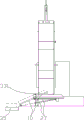
fig. 1 is a schematic perspective view of the present invention.
Fig. 2 is a front view of the present invention.
Fig. 3 is a front view of a preferred embodiment of the present invention.
Fig. 4 is a schematic structural diagram of the discharging driving cylinder in the invention.
FIG. 5 is a schematic view showing the structure of the discharging cylinder in the discharging operation of the present invention.
Fig. 6 is a top view of a preferred embodiment of the present invention.
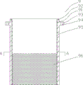
Fig. 7 is a schematic structural view of the inner barrel of the present invention.
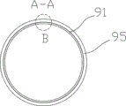
Fig. 8 is a schematic sectional view a-a of fig. 7.
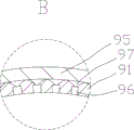
Fig. 9 is a partially enlarged schematic view of a portion B in fig. 8.
Fig. 10 is a hydraulic control schematic of the present invention.
FIG. 11 is a schematic diagram of an automatic control structure according to the present invention.
In the figure: a frame 1, a boom 2, a lifting hydraulic cylinder 3, a boom 4, a main hydraulic cylinder 5, a touch screen 6, a pressure head 7, a hydraulic station 8, a charging basket 9, an inner charging basket 91, an edge collar 92, a hanging collar 93, a connecting hole 94, an outer charging basket 95, an oil passing hole 96, a communicating groove 97, an oil receiving pan 10, a motor 11, a hydraulic pump 12, a first switching valve 13, a first switching valve 14, a second switching valve 15, a first overflow valve 16, a second overflow valve 17, a third overflow valve 18, a fourth overflow valve 19, a second switching valve 20, a third switching valve 21, a fourth switching valve 22, a fifth switching valve 23, a first flow sensor 24, a second flow sensor 25, a third flow sensor 26, a discharging driving cylinder 27, a feeding chute driving cylinder 28, a shutter driving cylinder 29, a weighing hopper 30, a weighing sensor 31, a rotary material opening 32, a base chute 33, a rotary feeding chute 34, a cake conveyor belt 35, PLC36, fourth flow sensor 37, bracket 38, squeezing pipeline 39, and third switching valve 40.
Detailed Description
Example 1:
as shown in fig. 1 to 5, a full-automatic hydraulic oil press comprises a frame 1, a main hydraulic cylinder 5 vertically installed is arranged in the frame 1, a bucket 9 with a through structure is arranged below the main hydraulic cylinder 5, a pressure head 7 sliding along the inner wall of the bucket 9 is arranged in the bucket 9, the pressure head 7 is connected with the main hydraulic cylinder 5, an oil receiving disc 10 is arranged at the bottom of the bucket 9, a lifting hydraulic cylinder 3 is fixedly arranged on the frame 1, the lifting hydraulic cylinder 3 is connected with the bucket 9 through a hanger rod 4 so as to lift the bucket 9 after oil pressing is completed, and cake pressing is convenient to take out;
the oil receiving disc 10 is connected with the base sliding groove 33 in a sliding mode, the discharging driving cylinder 27 is arranged between the base sliding groove 33 and the oil receiving disc 10, and the discharging driving cylinder 27 is used for driving the oil receiving disc 10 to slide along the base sliding groove 33 to discharge squeezed cakes. From this structure, can utilize lifting hydraulic cylinder 3 to promote charging bucket 9 after accomplishing the operation of extracting oil, press the cake and then stay on connecing the food tray, connect food tray 10 roll-off through the drive of the driving cylinder 27 drive of unloading to the convenient cake of pressing of taking out reduces intensity of labour by a wide margin.
In a preferred scheme, as shown in fig. 5, the base sliding chute 33 limits two sides of the oil receiving pan 10, one end of the discharging driving cylinder 27 is hinged with the oil receiving pan 10, the other end of the discharging driving cylinder 27 is hinged with the base sliding chute 33, the length of the base sliding chute 33 and the stroke of the discharging driving cylinder 27 are set to enable the oil receiving pan 10 to rotate for inclined discharging at an angle under the action of gravity after a piston rod of the discharging driving cylinder 27 is completely extended. Preferably, a slag cake conveyer belt 35 is arranged below the discharging position of the oil receiving pan 10, and more preferably, the slag cake conveyer belt 35 is arranged in the ground groove and conveys slag cakes to the next process for unified treatment. When the piston rod of the discharging driving cylinder 27 is completely retracted, the oil receiving tray 10 falls on the base sliding groove 33 under the action of gravity and is reset in a sliding manner. The oil receiving disc 10 reciprocates in the base sliding groove 33 in a teeterboard mode, and the discharging operation is realized by skillfully utilizing a driving mechanism. Specifically, the length of the base chute 33 is set such that when the piston rod of the discharge drive cylinder 27 is fully extended, the center of gravity of the drip pan 10 is pushed out of the end of the base chute 33. Thereby tilting the drip pan 10. And the discharge drive cylinder 27 can rotate therewith. Preferably, a structure for preventing collision is provided at the bottom of the oil pan 10, and stoppers for preventing the oil pan 10 from being separated from the base chute 33 are provided at both sides of the base chute 33.
In a preferred scheme, as shown in fig. 1-4, the frame 1 is a portal structure, and a cylinder body of a main hydraulic cylinder 5 is connected with the lower part of the top of the frame 1;
a piston rod of the main hydraulic cylinder 5 is connected with a pressure head 7;
an oil passing hole 96 for oil outlet is arranged on the side wall of the charging bucket 9;
an edge for blocking oil is arranged around the oil receiving disc 10, an opening for oil outlet is arranged on the edge, and the charging basket 9 is movably arranged on the oil receiving disc 10; with this structure, installation and debugging are facilitated.
The lifting hydraulic cylinder 3 is arranged above the top of the frame 1, the lifting hydraulic cylinder 3 is connected with the middle of the suspension arm 2, two ends of the suspension arm 2 are connected with the suspension rod 4, and the suspension rod 4 penetrates through the top of the frame 1 and is connected with the charging bucket 9. With the structure, the installation of the lifting hydraulic cylinder 3 is convenient, and after the charging basket 9 is lifted, no redundant shielding object is arranged around the cake squeezing, so that the operation of taking out the cake squeezing is convenient.
In a preferred scheme, as shown in fig. 7, a lifting lug or a suspension convex ring 93 for connecting the suspension rod 4 is arranged at the edge of the charging basket 9;
the lifting lug protrudes out of the outer surface of the charging bucket 9 along the radial direction, a connecting hole 94 for connecting the suspension rod 4 is formed in the lifting lug, and the end head of the suspension rod 4 is provided with threads;
the suspension convex ring 93 protrudes out of the outer surface of the charging bucket 9 along the radial direction, a connecting hole 94 for connecting the suspension rod 4 is formed in the suspension convex ring 93, and threads are formed in the end head of the suspension rod 4. With this structure, the mounting of the boom 4 is facilitated. Further preferably, the suspension rod 4 in this embodiment is a double-threaded screw, or a structure in which both ends of a steel pipe are connected to a double-threaded screw.
In a preferred scheme, as shown in fig. 3 and 6, a weighing hopper 30 is further arranged on one side of the rack 1, the weighing hopper 30 is in the prior art, as shown in fig. 3, a plurality of weighing sensors 31 are arranged on a bracket 38, and the weight of the materials in the weighing hopper 30 is weighed in a weightless manner through the weighing sensors 31, so that accurate feeding is realized.
The bottom of the weighing hopper 30 is provided with a rotary material opening 32, the rotary material opening 32 is connected with a rotary material inlet groove 34, and a material inlet groove driving cylinder 28 is arranged between the weighing hopper 30 and the rotary material inlet groove 34 so that the rotary material inlet groove 34 can move to the top position of the material barrel 9 or move away from the top position of the material barrel 9;
the bottom of the weighing hopper 30 is also provided with a gate plate, and a gate plate driving cylinder 29 is connected with the gate plate to drive the gate plate to open and close. When the material weighing device is used, the piston rod of the feed chute driving cylinder 28 extends out, the material opening of the rotary feed chute 34 is moved to the edge above the top opening of the material barrel 9, then the piston rod of the gate plate driving cylinder 29 extends out, the gate plate is opened, materials enter the material barrel 9 along the rotary feed chute 34, automatic feeding is achieved, when the weighing hopper 30 weighs the feeding weight, the feeding weight meets the set weight, the piston rod of the PLC driving gate plate driving cylinder 29 retracts, the gate plate is closed, the piston rod of the feed chute driving cylinder 28 retracts, the material opening of the rotary feed chute 34 is moved away from the top of the material barrel 9, and interference to the pressure head 7 is avoided. The ram drive cylinder 29 and the chute drive cylinder 28 in this example are preferably hydraulic cylinders, alternatively, air cylinders may be used.
In a preferred scheme, the charging basket 9 has at least a double-layer structure, the outer charging basket 95 is movably connected with the inner charging basket 91, the wall of one section of the inner charging basket 91 close to the bottom is provided with oil passing holes 96, and the outer wall of the inner charging basket 91 is provided with a plurality of communicating grooves 97 for mutually connecting the oil passing holes 96. From this structure, can improve the intensity of storage bucket 9 under the prerequisite of guaranteeing the effect of extracting oil, adopt higher pressure for example under 35 MPa's the operating mode, ensure that the storage bucket can not warp. And the processing difficulty of the oil passing hole 96 of the charging basket 9 can be reduced by reducing the thickness of the inner charging basket 91 and at least by reducing the length of the oil passing hole 96. In a preferred embodiment, the oil passing hole 96 is a circular hole, and preferably, the diameter of one end of the oil passing hole 96 close to the inner wall of the inner barrel 91 is smaller, and the diameter of one end close to the outer wall of the inner barrel 91 is larger. The oil passing holes 96 are arranged in a staggered manner; with this structure, the local strength can be prevented from being weakened. The communication groove 97 is a vertical groove or a spiral groove, and preferably a vertical groove. As shown in fig. 9, the orifice of the oil passing hole 96 is located at the bottom of the communication groove 97. With this structure, the machining length of the oil passing hole 96 can be reduced, and the machining cost can be reduced.
Or the charging basket 9 is of a single-layer structure, the wall of one section of the charging basket 9 close to the bottom is provided with an oil passing hole 96, the diameter of one end, close to the inner wall of the charging basket 9, of the oil passing hole 96 is smaller, and the diameter of one end, close to the outer wall of the charging basket 9, of the oil passing hole is larger.
Preferably, as shown in fig. 7, a rim protruding ring 92 is disposed at the top of the inner barrel 91, and the rim protruding ring 92 protrudes from the outer wall of the inner barrel 91 for axially limiting the inner barrel 91 in the outer barrel 95. In a preferred embodiment, as shown in fig. 7, screw holes are provided on the rim flange 92 to facilitate screwing screws against the outer barrel 95 to separate the inner barrel 91 from the outer barrel 95.
In a preferred scheme, as shown in fig. 10, a hydraulic station 8 is further provided, a hydraulic pump 12 of the hydraulic station 8 is connected with a first switching valve 13, the hydraulic pump 12 is mechanically connected with a motor 11, preferably, the motor 11 is controlled by frequency conversion, and the first switching valve 13 is respectively connected with a first reversing valve 14 and a second reversing valve 15 through pipelines;
the second reversing valve 15 is connected with a cavity for lifting of the lifting hydraulic cylinder 3 through a pipeline, a pipeline for overflowing is arranged on the second reversing valve 15, and a second overflow valve 17 is arranged on the overflowing pipeline;
the first reversing valve 14 is respectively connected with the two end cavities of the main hydraulic cylinder 5 through two pipelines, and the first reversing valve 14 is provided with a pipeline for returning oil;
the outlet of the hydraulic pump 12 is provided with a first relief valve 16. Through the switching of first switching valve 13, can squeeze between work and the control action and switch, the frequency conversion control of cooperation motor 11 realizes the balance of efficiency and energy consumption.
Preferably, as shown in fig. 10, the pressing pipeline 39 between the first direction changing valve 14 and the master cylinder 5 is further connected to an overflow pipeline, and the second switching valve 20 and the third overflow valve 18 are sequentially arranged on the overflow pipeline along an overflow path;
the two positions of the second switching valve 20 are a cut-off position and a conducting position respectively;
the relief pressure of the third relief valve 18 is smaller than the relief pressure of the first relief valve 16. With this configuration, the pre-pressure can be automatically realized by the automatic control of the PLC at a low pressure until the third relief valve 18 overflows, and then the second switching valve 20 is switched to the cutoff position to squeeze at a high pressure until the first relief valve 16 overflows.
In a preferred embodiment, as shown in fig. 10 and 11, the overflow ports of the first overflow valve 16, the second overflow valve 17 and the third overflow valve 18 are provided with flow sensors, and the flow sensors are connected with the PLC36, and the flow sensors are used for detecting whether liquid flows exist in the overflow ports and sending on-off signals, such as capacitive flow sensors with simple structure and low price, or non-contact ultrasonic flow sensors, although more expensive flow sensors are also feasible. In this example, the second flow sensor 25 is provided at the overflow port of the first relief valve 16, the first flow sensor 24 is provided at the overflow port of the second relief valve 17, and the third flow sensor 26 is provided at the overflow port of the third relief valve 18. In the scheme of the invention, only the overflow pressure parameter of the overflow valve needs to be adjusted, the control is simpler, the structure of the flow sensor is simple, the sealing of a pressure pipeline is not influenced due to low price, and the failure rate can be reduced. The scheme in the embodiment can adopt a cheaper manually-adjusted mechanical overflow valve, so that the control cost is further reduced. It is of course possible to use a more expensive digital relief valve.
In a preferred embodiment, as shown in fig. 10, one of the oil discharge lines of the first switching valve 13 is further connected to the third switching valve 40, in this embodiment, the first switching valve 13 is a three-position electromagnetic valve, and the oil discharge line is respectively communicated with the second direction switching valve 15, the first direction switching valve 14 and the third switching valve 40. The two positions of the third switching valve 40 are respectively a cut-off position and a conducting position, and the third switching valve 40 is connected with the third reversing valve 21, the fourth reversing valve 22 and the fifth reversing valve 23; the third switching valve 40 is also connected to the tank via an overflow line, which is provided in turn with a fourth overflow valve 19 and a fourth flow sensor 37 along an overflow path. The third direction valve 21, the fourth direction valve 22 and the fifth direction valve 23 are three-position solenoid valves, wherein one position is a cut-off position, and the other two positions are a through position and a direction change position respectively.
The third reversing valve 21 is connected with the discharging driving cylinder 27 through two pipelines, the fourth reversing valve 22 is connected with the feeding chute driving cylinder 28 through two pipelines, the fifth reversing valve 23 is connected with the flashboard driving cylinder 29 through two pipelines, and the third reversing valve 21, the fourth reversing valve 22 and the fifth reversing valve 23 are provided with oil return pipes. By the structure, automatic control of discharging and feeding is realized.
The flow sensor in the embodiment selects a low-cost flow sensor as much as possible, only needs to acquire whether a switching signal that the flow passes through exists, and does not need to detect the flow, so that the element cost can be greatly reduced.
Preferably, as shown in fig. 11, the first flow sensor 24, the second flow sensor 25, the third flow sensor 26 and the fourth flow sensor 37 are electrically connected to the PLC36 for collecting whether the overflow ports of the respective overflow valves have overflow flow. The weighing sensor 31 is electrically connected with the PLC36 and is used for acquiring the weight of the material in the weighing hopper 30, and in this example, the weight of the material entering the material barrel 9 is judged according to the weight of the material loss. The first switching valve 13 is electrically connected to the PLC36 for switching the supply of the oil to the main hydraulic cylinder 5 or to at least one of the lift hydraulic cylinder 3, the discharge drive cylinder 27, the feed chute drive cylinder 28, and the shutter drive cylinder 29. So that the squeezing work and the motion control of the equipment do not interfere with each other. The first direction valve 14 is electrically connected to the PLC36 to control the ram 7 of the master cylinder 5 to be raised or lowered. The second direction valve 15 is electrically connected with the PLC36 to control the lifting of the bucket 9 driven by the lifting hydraulic cylinder 3. The third switching valve 40 is electrically connected with the PLC36 to control the on-off of the oil paths of the discharging driving cylinder 27, the feeding chute driving cylinder 28 and the gate plate driving cylinder 29. The third reversing valve 21, the fourth reversing valve 22 and the fifth reversing valve 23 are electrically connected with the PLC36 and are respectively used for controlling the extension and contraction of piston rods of the brake material discharging driving cylinder 27, the feed chute driving cylinder 28 and the gate plate driving cylinder 29. The motor 11 is electrically connected to the PLC36 to adjust the speed of the motor 11 through variable frequency control, preferably, to provide high speed and low pressure hydraulic oil during the operation control of the device. During the press control of the equipment, hydraulic oil with low speed and high pressure is provided.
Example 2:
on the basis of embodiment 1, an automatic control method adopting the full-automatic hydraulic oil press comprises the following steps:
s1, during the squeezing operation, the first switching valve 13 is first controlled to supply oil to the first switching valve 14, the second switching valve 20 is turned on, and the ram 7 of the master cylinder 5 is pressed down;
s2, until the third overflow valve 18 overflows, the third flow sensor 26 collects an overflow signal to close the second switching valve 20, and the pressure head 7 of the main hydraulic cylinder 5 continues to press down;
s3, until the first overflow valve 16 overflows, the second flow sensor 25 collects overflow signals, so that the first reversing valve 14 is reversed, and the pressure head 7 of the main hydraulic cylinder 5 is lifted;
s4, the first switching valve 13 switches to supply oil to the second switching valve 15, so that the lifting hydraulic cylinder 3 lifts the charging basket 9 until the second overflow valve 17 overflows, and the first flow sensor 24 collects overflow signals to control automatic discharging;
through the steps, full-automatic oil pressing is realized.
In a preferred embodiment, taking the optimal embodiment as an example, the whole control steps include:
s01, it is also possible to control the first switching valve 13 to supply oil to the first direction switching valve 14, and preferably to set the second switching valve 20 in a conductive state or a non-conductive state. The first reversing valve 14 switches to supply oil to a cavity below the main hydraulic cylinder 5, so that the pressure head 7 is lifted;
s02, the first switching valve 13 switches to supply oil to the third switching valve 40, the third switching valve 40 is opened, the fourth switching valve 22 is directly communicated, the piston rod of the feed chute driving cylinder 28 extends out, the rotary feed chute 34 rotates to the position above the charging bucket 9, and the fourth switching valve 22 is in a stop position. The fifth reversing valve 23 is communicated, so that a piston rod of the flashboard driving cylinder 29 extends out, the flashboard is opened, and the material to be squeezed enters the charging bucket 9; automatic feeding is realized.
S03, when the weight signal acquired by the weighing sensor 31 reaches a preset value, the fifth reversing valve 23 reverses to close the gate plate, the fourth reversing valve 22 reverses to enable the rotary feeding chute 34 to leave from the upper part of the charging bucket 9, and the feeding process is completed. The stroke of the feed chute driving cylinder 28 and the gate plate driving cylinder 29 is controlled by the acquired overflow signal of the fourth flow sensor 37 in the control process.
S04, the first switching valve 13 switches the supply of oil to the first switching valve 14, and the second switching valve 20 is turned on, and the ram 7 of the master cylinder 5 is pressed down;
s05, until the third overflow valve 18 overflows, the third flow sensor 26 collects an overflow signal to stop the second switching valve 20, and the pressure head 7 of the main hydraulic cylinder 5 continues to press down;
s06, until the first overflow valve 16 overflows, the second flow sensor 25 collects overflow signals, so that the first reversing valve 14 is reversed, and the pressure head 7 of the main hydraulic cylinder 5 is lifted;
s07, the first switching valve 13 switches to supply oil to the second switching valve 15, so that the lifting hydraulic cylinder 3 lifts the charging basket 9 until the second overflow valve 17 overflows, the first flow sensor 24 collects overflow signals, the second switching valve 15 also has a stop position, and the second switching valve 15 is switched to the stop position holding state;
s08, the first switching valve 13 switches to supply oil to the third switching valve 40, the third switching valve 21 is straight, the piston rod of the discharging driving cylinder 27 extends out to drive the oil receiving disc 10 to slide along the base sliding chute 33 until the oil receiving disc tilts under the action of gravity, the slag cake is discharged obliquely, and preferably, the slag cake falls onto the slag cake conveying belt 35 on one side and is conveyed to the next working procedure for centralized processing.
S09, the third reversing valve 21 reverses to drive the oil receiving disc 10 to reset and slide along the base sliding groove 33 until the oil receiving disc returns to the horizontal state under the action of gravity, and the reset action of the oil receiving disc 10 after unloading is completed. And finishing the whole unloading action.
S10, the first switching valve 13 switches to supply oil to the second switching valve 15, the second switching valve 15 switches, and the lifting hydraulic cylinder 3 enables the charging bucket 9 to be placed on the oil receiving disc 10 to wait for the next squeezing operation.
The full-automatic control of feeding, prepressing, squeezing and discharging is realized through the steps.
Further preferably, in step S05, while the ram 7 of the master cylinder 5 continues to be depressed, the PLC36 controls the motor 11 to enter the low-speed high-pressure operation mode to increase the output pressure of the ram 7 during the pressing operation.
The full-automatic hydraulic oil press has the advantages that: the hydraulic pressure is adjustable through a variable frequency motor; manual and automatic control can be freely switched; the stroke and the running frequency are both adjustable; reasonable in design, simple to use, easy maintenance. The production line is prepared, the production efficiency is high, and the one-time yield is large; one person can simultaneously operate the whole production line, so that the cost is reduced. In particular, the structure of the invention is very suitable for cold pressing production of woody oil.
The above-described embodiments are merely preferred embodiments of the present invention, and should not be construed as limiting the present invention, and features in the embodiments and examples in the present application may be arbitrarily combined with each other without conflict. The protection scope of the present invention is defined by the claims, and includes equivalents of technical features of the claims. I.e., equivalent alterations and modifications within the scope hereof, are also intended to be within the scope of the invention.
Claims (8)
1. The utility model provides a full-automatic hydraulic oil press, it includes frame (1), is equipped with main hydraulic cylinder (5) of vertical installation in frame (1), and main hydraulic cylinder (5) below is equipped with storage bucket (9) that link up the structure, is equipped with in storage bucket (9) along the gliding pressure head (7) of storage bucket (9) inner wall, and pressure head (7) are connected with main hydraulic cylinder (5), are equipped with in the bottom of storage bucket (9) and connect food tray (10), characterized by: a lifting hydraulic cylinder (3) is fixedly arranged on the rack (1), and the lifting hydraulic cylinder (3) is connected with the charging basket (9) through a suspender (4) so as to lift the charging basket (9) after oil extraction is finished, thereby facilitating the taking out of pressed cakes;
the oil receiving disc (10) is in sliding connection with the base sliding groove (33), a discharging driving cylinder (27) is arranged between the base sliding groove (33) and the oil receiving disc (10), and the discharging driving cylinder (27) is used for driving the oil receiving disc (10) to slide along the base sliding groove (33) to discharge pressed cakes;
the oil receiving disc (10) is limited at two sides by the base sliding groove (33), one end of the discharging driving cylinder (27) is hinged with the oil receiving disc (10), the other end of the discharging driving cylinder is hinged with the base sliding groove (33), after a piston rod of the discharging driving cylinder (27) is completely extended out, the gravity center of the oil receiving disc (10) is positioned outside the end of the base sliding groove (33), the oil receiving disc (10) rotates for an angle under the action of gravity to discharge, and after the piston rod of the discharging driving cylinder (27) is completely retracted, the oil receiving disc (10) falls on the base sliding groove (33) under the action of gravity to slide and reset;
the hydraulic pump (12) of the hydraulic station (8) is connected with a first switching valve (13), and the first switching valve (13) is respectively connected with a first reversing valve (14) and a second reversing valve (15) through pipelines;
the second reversing valve (15) is connected with a cavity for lifting of the lifting hydraulic cylinder (3) through a pipeline, a pipeline for overflowing is arranged on the second reversing valve (15), and a second overflow valve (17) is arranged on the pipeline for overflowing;
the first reversing valve (14) is respectively connected with the cavities at the two ends of the main hydraulic cylinder (5) through two pipelines, and the first reversing valve (14) is provided with a pipeline for returning oil;
the outlet of the hydraulic pump (12) is provided with a first overflow valve (16).
2. The full-automatic hydraulic oil press according to claim 1, wherein: the frame (1) is of a portal structure, and the cylinder body of the main hydraulic cylinder (5) is connected with the lower part of the top of the frame (1);
a piston rod of the main hydraulic cylinder (5) is connected with the pressure head (7);
an oil passing hole (96) for oil outlet is arranged on the side wall of the charging bucket (9);
an edge for blocking oil is arranged around the oil receiving disc (10), an opening for discharging oil is arranged on the edge, and the charging bucket (9) is movably arranged on the oil receiving disc (10);
the lifting hydraulic cylinder (3) is arranged above the top of the frame (1), the lifting hydraulic cylinder (3) is connected with the middle of the suspension arm (2), the two ends of the suspension arm (2) are connected with the suspension rod (4), and the suspension rod (4) penetrates through the top of the frame (1) and is connected with the charging bucket (9).
3. The full-automatic hydraulic oil press according to claim 2, wherein: a weighing hopper (30) is further arranged on one side of the rack (1), a rotary material opening (32) is formed in the bottom of the weighing hopper (30), the rotary material opening (32) is connected with a rotary material inlet groove (34), and a material inlet groove driving cylinder (28) is arranged between the weighing hopper (30) and the rotary material inlet groove (34) so that the rotary material inlet groove (34) can move to the top position of the material barrel (9) or move away from the top position of the material barrel (9);
the bottom of the weighing hopper (30) is also provided with a gate plate, and a gate plate driving cylinder (29) is connected with the gate plate to drive the gate plate to open and close.
4. The full-automatic hydraulic oil press according to any one of claims 1 to 3, characterized in that: the charging basket (9) is at least of a double-layer structure, the outer charging basket (95) is movably connected with the inner charging basket (91), oil passing holes (96) are formed in the wall of one section, close to the bottom, of the inner charging basket (91), and a plurality of communicating grooves (97) which mutually connect the oil passing holes (96) are formed in the outer wall of the inner charging basket (91);
or the charging bucket (9) is of a single-layer structure, an oil passing hole (96) is formed in one section of wall, close to the bottom, of the charging bucket (9), the diameter of one end, close to the inner wall of the charging bucket (9), of the oil passing hole (96) is smaller, and the diameter of one end, close to the outer wall of the charging bucket (9), of the oil passing hole is larger.
5. The full-automatic hydraulic oil press according to claim 1, wherein: a squeezing pipeline (39) between the first reversing valve (14) and the main hydraulic cylinder (5) is also connected with an overflow pipeline, and a second switching valve (20) and a third overflow valve (18) are sequentially arranged on the overflow pipeline along an overflow path;
two bits of the second switching valve (20) are respectively a cut-off bit and a conduction bit;
the relief pressure of the third relief valve (18) is lower than the relief pressure of the first relief valve (16).
6. The full-automatic hydraulic oil press according to claim 5, wherein: overflow ports of the first overflow valve (16), the second overflow valve (17) and the third overflow valve (18) are provided with flow sensors, and the flow sensors are connected with a PLC (36);
the flow sensor is used for detecting whether liquid flow exists at the overflow port.
7. The full-automatic hydraulic oil press according to claim 6, wherein: one oil discharge pipeline of the first switching valve (13) is also connected with a third switching valve (40), two positions of the third switching valve (40) are a cut-to position and a conduction position respectively, and the third switching valve (40) is connected with a third reversing valve (21), a fourth reversing valve (22) and a fifth reversing valve (23);
the third reversing valve (21) is connected with the discharging driving cylinder (27) through two pipelines, the fourth reversing valve (22) is connected with the feeding chute driving cylinder (28) through two pipelines, the fifth reversing valve (23) is connected with the flashboard driving cylinder (29) through two pipelines,
the third reversing valve (21), the fourth reversing valve (22) and the fifth reversing valve (23) are provided with oil return pipes.
8. An automatic control method using the full-automatic hydraulic oil press according to claim 6, characterized by comprising the steps of:
s1, when squeezing operation is performed, the first switching valve (13) is controlled to supply oil to the first switching valve (14), the second switching valve (20) is conducted, and the pressure head (7) of the main hydraulic cylinder (5) is pressed down;
s2, until the third overflow valve (18) overflows, the third flow sensor (26) collects an overflow signal to close the second switching valve (20), and the pressure head (7) of the main hydraulic cylinder (5) continues to press downwards;
s3, until the first overflow valve (16) overflows, the second flow sensor (25) collects overflow signals, so that the first reversing valve (14) is reversed, and the pressure head (7) of the main hydraulic cylinder (5) is lifted;
s4, the first switching valve (13) switches to supply oil to the second switching valve (15), so that the lifting hydraulic cylinder (3) lifts the charging basket (9) until the second overflow valve (17) overflows, the first flow sensor (24) acquires an overflow signal and controls automatic or manual discharging;
through the steps, full-automatic oil pressing is realized.
Priority Applications (1)
| Application Number | Priority Date | Filing Date | Title |
|---|---|---|---|
| CN201911179637.0A CN110901129B (en) | 2019-11-27 | 2019-11-27 | Full-automatic hydraulic oil press and control method |
Applications Claiming Priority (1)
| Application Number | Priority Date | Filing Date | Title |
|---|---|---|---|
| CN201911179637.0A CN110901129B (en) | 2019-11-27 | 2019-11-27 | Full-automatic hydraulic oil press and control method |
Publications (2)
| Publication Number | Publication Date |
|---|---|
| CN110901129A CN110901129A (en) | 2020-03-24 |
| CN110901129B true CN110901129B (en) | 2021-01-08 |
Family
ID=69819958
Family Applications (1)
| Application Number | Title | Priority Date | Filing Date |
|---|---|---|---|
| CN201911179637.0A Active CN110901129B (en) | 2019-11-27 | 2019-11-27 | Full-automatic hydraulic oil press and control method |
Country Status (1)
| Country | Link |
|---|---|
| CN (1) | CN110901129B (en) |
Families Citing this family (6)
| Publication number | Priority date | Publication date | Assignee | Title |
|---|---|---|---|---|
| CN111908153B (en) * | 2020-07-10 | 2021-11-05 | 吕战奎 | Automatic filling machine for oil cake production |
| CN112959721A (en) * | 2021-02-01 | 2021-06-15 | 一重集团大连工程技术有限公司 | Primary compressor for compaction treatment in middle-low radioactive solid waste barrel |
| CN112873980A (en) * | 2021-03-02 | 2021-06-01 | 四川财牛食品有限公司 | Animal oil residue pressing device |
| CN116766668A (en) * | 2021-12-20 | 2023-09-19 | 徐意 | An oil press for edible oil production |
| CN115558552B (en) * | 2022-09-29 | 2024-06-18 | 恒利康生物科技股份有限公司 | Essential oil extraction and squeezing mechanism and squeezing method thereof |
| CN116476432B (en) * | 2023-05-23 | 2024-07-09 | 河北鼎康粮油有限公司 | Walnut oil press |
Citations (4)
| Publication number | Priority date | Publication date | Assignee | Title |
|---|---|---|---|---|
| CN2644511Y (en) * | 2003-08-28 | 2004-09-29 | 曹珍 | Hydraulic system of static pile pressing machine |
| CN203410050U (en) * | 2013-07-19 | 2014-01-29 | 山东源泉机械有限公司 | Novel lifting-type hydraulic oil press |
| CN107116831A (en) * | 2017-04-24 | 2017-09-01 | 廉振宏 | A kind of efficient oil discharging device of hydraulic oil press |
| CN206605017U (en) * | 2017-03-27 | 2017-11-03 | 宣化钢铁集团有限责任公司 | A kind of six rollers two driving straightening hydraulic system |
Family Cites Families (6)
| Publication number | Priority date | Publication date | Assignee | Title |
|---|---|---|---|---|
| CN202507566U (en) * | 2012-02-12 | 2012-10-31 | 常德市恒德机械制造有限公司 | Vertical type micropore oil press |
| CN203063145U (en) * | 2013-03-02 | 2013-07-17 | 临沂为民机械有限公司 | Disc type hydraulic vertical oil press |
| CN204036895U (en) * | 2014-08-29 | 2014-12-24 | 樊祜运 | A kind of horizontal three-dimensional oil press |
| CN207209472U (en) * | 2017-08-31 | 2018-04-10 | 浙江力琦机械有限公司 | Efficient multi-cavity automatic material weighing machine |
| KR101853945B1 (en) * | 2018-03-16 | 2018-05-02 | 백승훈 | extractor for edible plant oil |
| CN108859211A (en) * | 2018-07-03 | 2018-11-23 | 青岛农业大学 | One cultivates peanut oil press |
-
2019
- 2019-11-27 CN CN201911179637.0A patent/CN110901129B/en active Active
Patent Citations (4)
| Publication number | Priority date | Publication date | Assignee | Title |
|---|---|---|---|---|
| CN2644511Y (en) * | 2003-08-28 | 2004-09-29 | 曹珍 | Hydraulic system of static pile pressing machine |
| CN203410050U (en) * | 2013-07-19 | 2014-01-29 | 山东源泉机械有限公司 | Novel lifting-type hydraulic oil press |
| CN206605017U (en) * | 2017-03-27 | 2017-11-03 | 宣化钢铁集团有限责任公司 | A kind of six rollers two driving straightening hydraulic system |
| CN107116831A (en) * | 2017-04-24 | 2017-09-01 | 廉振宏 | A kind of efficient oil discharging device of hydraulic oil press |
Also Published As
| Publication number | Publication date |
|---|---|
| CN110901129A (en) | 2020-03-24 |
Similar Documents
| Publication | Publication Date | Title |
|---|---|---|
| CN110901129A (en) | Full-automatic hydraulic oil press and control method | |
| CN102431196B (en) | Vertical/horizontal automatic squeezer | |
| CN206317422U (en) | A kind of automatic squeezer machine | |
| CN103950669A (en) | Back loading type garbage compression vehicle | |
| CN211279860U (en) | Full-automatic hydraulic oil press | |
| CN110878774B (en) | Hydraulic control system and control method for full-automatic hydraulic oil press | |
| CN211074801U (en) | Vertical oil press | |
| CN110089913A (en) | A kind of stoste system of processing and stoste processing method | |
| CN207789804U (en) | A kind of continuous squeezing dewatering machine | |
| CN116768445A (en) | A vertical vortex stirring honeycomb pressing and backwashing machine | |
| CN204470583U (en) | Aluminum-alloy wheel brute force casting liquid feeding system | |
| CN220224780U (en) | Paper plastic tableware forming machine | |
| CN201442358U (en) | Full-automatic hydraulic oil press | |
| CN110819441B (en) | Processing technology for physically squeezing oil | |
| CN203410089U (en) | Feeding device for squeezer | |
| CN105962162A (en) | Porphyra production line | |
| CN206277686U (en) | A kind of single oil cylinder frame bar squeezer | |
| CN203876256U (en) | Hydraulic vacuum type oil press | |
| CN213564524U (en) | Mulberry wine preparation is with high-efficient broken mixing arrangement of mulberry | |
| CN105172184B (en) | Household kitchen garbage cutting and compacting device and method | |
| CN211138264U (en) | Automatic feeding device of hydraulic oil press | |
| CN110789165B (en) | Squeezing equipment convenient for cleaning internal residues | |
| CN113500810B (en) | Numerical control oil press capable of automatically feeding | |
| CN218620749U (en) | Berry wine fermenting installation | |
| CN219820739U (en) | Full-automatic tablet press |
Legal Events
| Date | Code | Title | Description |
|---|---|---|---|
| PB01 | Publication | ||
| PB01 | Publication | ||
| SE01 | Entry into force of request for substantive examination | ||
| SE01 | Entry into force of request for substantive examination | ||
| GR01 | Patent grant | ||
| GR01 | Patent grant | ||
| TA01 | Transfer of patent application right |
Effective date of registration: 20201228 Address after: 672599 Dianmian Road, cangshanxi Town, Yangbi Yi Autonomous County, Dali Bai Autonomous Prefecture, Yunnan Province Applicant after: Yunnan Dongfanghong Biotechnology Co.,Ltd. Address before: 432600 Liangji North Road, Anlu City, Xiaogan City, Hubei Province Applicant before: HUBEI DONGFANGHONG GRAIN MACHINERY Co.,Ltd. |
|
| TA01 | Transfer of patent application right |