Split type wheel hub motor convenient to dismouting is aerifyd child and is child with vacuum
Technical Field
The invention relates to a hub motor, in particular to a split type hub motor convenient for dismounting an inflatable tire and a vacuum tire.
Background
The hub motor is a motor capable of realizing independent driving of a single wheel, is commonly used for the electric vehicle, can form a complete wheel only by sleeving a tire on a hub outside the hub motor, and can drive the tire to rotate to walk when the hub motor runs, so that the electric vehicle is driven to move forwards or backwards.
The hub of the traditional hub motor is actually the outer rotor of the hub motor, and is integrated with the motor and inseparably exists, in real life, the hub of the hub motor is easy to deform or lose due to the uncertain road conditions, because the hub motor and the hub are of an integral structure, once the hub is damaged, the whole hub motor can be replaced, the replacement cost is extremely high, if the hub is to be replaced independently, because wheel hub is as wheel hub motor's external rotor, and the change just can be accomplished to simple dismouting, needs the professional knowledge in this field, and if the driving personnel change privately, very easily causes the inside damage of wheel hub motor, need transport it to professional maintenance place and can change, and is very troublesome, is difficult to restore intact with wheel hub motor the very first time, influences driving personnel's schedule.
The hub of the traditional hub motor is limited by rims on two sides of the hub, so that the pneumatic tire or the vacuum tire can not be disassembled and assembled automatically, a special tire disassembling machine is required to be used for disassembling the pneumatic tire or the vacuum tire, once the pneumatic tire or the vacuum tire is damaged, the replacement process becomes very troublesome, and the efficiency is extremely low.
Disclosure of Invention
The invention aims to solve the technical problem of providing a split type hub motor convenient for dismounting an inflatable tire and a vacuum tire, which can quickly finish the replacement of the hub when the hub is damaged, does not need to worry about the damage to the inside of the hub motor in the replacement process, is convenient for a driver to replace by himself, and can quickly finish the dismounting of the inflatable tire or the vacuum tire without a tire dismounting machine.
The technical scheme adopted by the invention for solving the technical problems is as follows:
the invention discloses a split type hub motor convenient for dismounting an inflatable tire and a vacuum tire, which comprises a motor body and is characterized in that: the left part of the motor body is externally sleeved with a left wheel hub body, and the right part of the motor body is externally sleeved with a right wheel hub body; the right end face of the left hub body is attached to the left end face of the right hub body, and a sealing device is arranged between the right end face of the left hub body and the left end face of the right hub body; the left wheel hub body and the right wheel hub body are spliced to form a wheel hub, and an annular tire mounting groove is formed in the wheel hub; a plurality of first fixed blocks which are uniformly distributed in the circumferential direction are arranged on the inner wall of the left side of the right wheel hub body; the outer wall of the right part of the motor body is provided with a plurality of second fixed blocks corresponding to the first fixed blocks in position, and the second fixed blocks are attached to the side wall of the right side of the first fixed blocks; a plurality of third fixed blocks corresponding to the first fixed blocks are arranged on the inner wall of the right side of the left hub body, the third fixed blocks are attached to the side wall of the left side of the first fixed blocks, and the third fixed blocks, the first fixed blocks and the second fixed blocks are fixed through motor fastening screws; a plurality of uniformly distributed fourth fixed blocks are arranged on the inner wall of the left side of the right hub body; a plurality of fifth fixing blocks corresponding to the fourth fixing blocks are arranged on the inner wall of the right side of the left hub body; and the fourth fixing block and the fifth fixing block are fixed through a hub fastening screw.
The right part of the motor body is provided with a right motor cover, and the right motor cover and the motor body are fixed through a right motor cover fastening screw; the second fixed block is circumferentially and uniformly distributed on the outer peripheral surface of the right motor cover.
The motor body left side lid closes a left motor lid, fixes mutually through left motor lid fastening screw between left motor lid and the motor body.
The first fixing block is provided with a first screw hole, the second fixing block is provided with a second screw hole, the third fixing block is provided with a third screw hole, the first screw hole, the second screw hole and the third screw hole are coaxial, and the motor fastening screw is simultaneously screwed in the first screw hole, the second screw hole and the third screw hole; and a fourth screw hole is formed in the fourth fixing block, a fifth screw hole coaxial with the fourth screw hole is formed in the fifth fixing block, and the wheel hub fastening screw is simultaneously screwed in the fourth screw hole and the fifth screw hole.
Clamping steps which are symmetrical to each other are arranged on the right side of the first fixing block and the left side of the third fixing block, and the second fixing block is attached to the clamping steps on the right side of the first fixing block.
The sealing device comprises a sealing groove arranged on the right end face of the left hub body, and the sealing groove is annular; and a sealing ring matched with the sealing groove is arranged in the sealing groove.
The invention has the beneficial effects that:
compared with the prior art, the hub of the split hub motor which adopts the structure of the invention and is convenient for dismounting the inflatable tire and the vacuum tire consists of the left hub body and the right hub body, when the hub of the hub motor is damaged, the damage can be inevitably generated on the left hub body or the right hub body, because the left hub body, the right hub body and the motor body are mutually independent, when the left hub body or the right hub body is damaged, only the left hub body or the right hub body is required to be independently replaced, the whole hub motor is not required to be replaced, the replacement cost is effectively reduced, the hub formed by splicing the left hub body and the right hub body is like a shell relative to the hub motor, the hub motor is dismounted, the performance of the hub motor can not be influenced, and the left hub body, the right hub body and the motor body are fixed with the hub fastening screws through the motor fastening screws, the left wheel hub body, the right wheel hub body and the motor body can be quickly disassembled and assembled only by operating the motor fastening screws and the wheel hub fastening screws, professional knowledge is not needed in the replacement work, a vehicle driver can quickly disassemble and assemble the vehicle driver by himself, the maintenance trouble that the damaged wheel hub motor needs to be conveyed to a professional maintenance place is reduced, along with the separation of the left wheel hub body and the right wheel hub body, one or both of rims on the two sides of the wheel hub can not limit the inflating tire or the vacuum tire mounted in the tire mounting groove, the tire can directly slide out from the side edge of the wheel hub, the inflating tire or the vacuum tire can be quickly disassembled and assembled without using a tire disassembling machine, time and labor are saved, the replacement efficiency is effectively improved, and the labor intensity and the after-sale cost are reduced.
Drawings
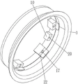
FIG. 1 is an angular schematic view of a split hub motor for facilitating the assembly and disassembly of an inflatable tire and a vacuum tire in accordance with the present invention;
FIG. 2 is a schematic structural view of another angle of the split hub motor for facilitating the assembly and disassembly of the pneumatic tire and the vacuum tire in accordance with the present invention;
FIG. 3 is a schematic structural view of the left hub body;
FIG. 4 is a schematic structural view of the right hub body;
fig. 5 is a schematic structural view of a motor body;
FIG. 6 is a perspective view of the split hub motor for easy assembly and disassembly of the pneumatic tire and the vacuum tire according to the present invention.
Detailed Description
The invention is described in further detail below with reference to the following figures and detailed description:
referring to fig. 1 to 6, the present invention provides a split hub motor for conveniently dismounting an inflatable tire and a vacuum tire, which comprises a motor body 1, wherein a left hub body 2 is sleeved outside the left portion of the motor body 1, and a right hub body 3 is sleeved outside the right portion of the motor body 1; the right end face of the left hub body 2 is attached to the left end face of the right hub body 3, and a sealing device is arranged between the right end face of the left hub body 2 and the left end face of the right hub body 3; the left hub body 2 and the right hub body 3 are spliced to form a hub 4, and an annular tire mounting groove 5 is formed in the hub 4; a plurality of first fixed blocks 6 which are uniformly distributed in the circumferential direction are arranged on the inner wall of the left side of the right hub body 3; a plurality of second fixing blocks 7 corresponding to the first fixing blocks 6 are arranged on the outer wall of the right part of the motor body 1, and the second fixing blocks 7 are attached to the side wall of the right side of the first fixing blocks 6; a plurality of third fixing blocks 8 corresponding to the first fixing blocks 6 are arranged on the inner wall of the right side of the left hub body 2, the third fixing blocks 8 are attached to the side wall of the left side of the first fixing blocks 6, and the third fixing blocks 8, the first fixing blocks 6 and the second fixing blocks 7 are fixed through motor fastening screws 9; a plurality of evenly distributed fourth fixed blocks 10 are arranged on the inner wall of the left side of the right hub body 3; a plurality of fifth fixing blocks 11 corresponding to the fourth fixing blocks 10 are arranged on the inner wall of the right side of the left hub body 2; the fourth fixing block 10 and the fifth fixing block 11 are fixed together by a hub fastening screw 12.
A right motor cover 13 is arranged at the right part of the motor body 1, and the right motor cover 13 and the motor body 1 are fixed through a right motor cover fastening screw 14; the second fixing blocks 7 are circumferentially and uniformly distributed on the outer peripheral surface of the right motor cover 13.
The left side cover of the motor body 1 is provided with a left motor cover 15, and the left motor cover 15 and the motor body 1 are fixed through a left motor cover fastening screw 16.
The first fixing block 6 is provided with a first screw hole 17, the second fixing block 7 is provided with a second screw hole 18, the third fixing block 8 is provided with a third screw hole 19, the first screw hole 17, the second screw hole 18 and the third screw hole 19 are coaxial, and the motor fastening screw 9 is simultaneously screwed in the first screw hole 17, the second screw hole 18 and the third screw hole 19; the fourth fixing block 10 is provided with a fourth screw hole 20, the fifth fixing block 11 is provided with a fifth screw hole 21 coaxial with the fourth screw hole 20, and the hub fastening screw 12 is simultaneously screwed in the fourth screw hole 20 and the fifth screw hole 21.
The right side of the first fixed block 6 and the left side of the third fixed block 8 are provided with clamping steps 22 which are symmetrical to each other, and the second fixed block 7 is attached to the clamping step 22 on the right side of the first fixed block 6.
The sealing device comprises a sealing groove 23 arranged on the right end face of the left hub body 2, and the sealing groove 23 is annular; a sealing ring 24 matched with the sealing groove 23 is arranged in the sealing groove.
The using method of the invention is as follows:
before the hub motor is used, a tire can be arranged in a tire installation groove 5 of a hub 4, when the tire is inflated, a complete wheel can be formed for running, the hub 4 consists of a left hub body 2 and a right hub body 3, when the hub 4 of the hub motor is damaged, the damage can be inevitably generated on the left hub body 2 or the right hub body 3, because the left hub body 2, the right hub body 3 and the motor body 1 are mutually independent, when the left hub body 2 or the right hub body 3 is damaged, only the left hub body 2 or the right hub body 3 is required to be independently replaced without replacing the whole hub motor, the replacement cost is effectively reduced, and the hub formed by splicing the left hub body 2 and the right hub body 3 is like a shell relative to the hub motor, and is detached from the hub motor, so that the performance of the hub motor can not be influenced, the left wheel hub body 2, the right wheel hub body 3 and the motor body 1 are fixed with the wheel hub fastening screws 12 through the motor fastening screws 9, the dismounting and mounting of the left wheel hub body 2, the right wheel hub body 3 and the motor body 1 can be quickly completed only by operating the motor fastening screws 9 and the wheel hub fastening screws 12, the replacement work does not need professional knowledge, a vehicle operator can quickly complete the dismounting and mounting work by himself, the maintenance trouble that the damaged wheel hub motor needs to be sent to a professional maintenance place is reduced, and along with the separation of the left wheel hub body and the right wheel hub body, one or both of the wheel rims on the two sides of the wheel hub can not limit the inflating tire or the vacuum tire arranged in the tire mounting groove, the tire can directly slide out from the side edge of the wheel hub, the tire or the vacuum tire does not need to be dismounted from the tire mounting groove by using a tire dismounting machine, the dismounting and mounting of the inflating tire or the vacuum tire can be quickly completed, time and labor are saved, the replacement efficiency is effectively improved, and the labor intensity and the after-sale cost are reduced.
When the hub motor needs to be disassembled, the motor fastening screws 9 or the hub fastening screws 12 can be selected for disassembling, after the motor fastening screws 9 are sequentially screwed out from the second screw holes 18, the first screw holes 17 and the third screw holes 19, the motor body 1, the left hub body 2 and the right hub body 3 are not mutually connected and fixed any more, at this time, the motor body 1 can complete the separation of the motor body 1 and the hub 4, if the left hub body 2 and the right hub body 3 are required to be separated, the hub fastening screws 12 can be sequentially screwed out from the fourth screw holes 20 and the fifth screw holes 21, at this time, the left hub body 2 and the right hub body 3 are not connected any more, only the damaged left hub body 2 or right hub body 3 needs to be replaced, and after the new left hub body 2 or right hub body 3 is replaced, the assembly work of the hub motor can be completed through the hub fastening screws 12 and the motor fastening screws 9 again, in fact, the existence of the motor fastening screw 9 can fix the left hub body 2, the right hub body 3 and the motor body 1 through the first fixing block 6, the second fixing block 7 and the third fixing block 8, and the existence of the hub fastening screw 12 can further fasten the left hub body 2 and the right hub body 3 through the fixing between the fourth fixing block 10 and the fifth fixing block 11, so that not only is the sealing performance between the right end surface of the left hub body 2 and the left end surface of the right hub body 3 ensured, but also the fastening force between the left hub body 2 and the right hub body 3 can further fasten the motor body 1, and the stability in fastening the three parts is ensured to the maximum extent.
The right part of the motor body 1 is provided with a right motor cover 13, the right motor cover 13 is fixed with the motor body 1 through a right motor cover fastening screw 14, the second fixing block 7 is circumferentially and uniformly distributed on the outer peripheral surface of the right motor cover 13, a left motor cover 15 is combined with the left motor cover 1, the left motor cover 15 is fixed with the motor body 1 through a left motor cover fastening screw 16, only the right motor cover fastening screw 14 needs to be disassembled to complete the separation between the right motor cover 13 and the motor body 1, the left motor cover fastening screw 16 is disassembled to complete the separation between the left motor cover 15 and the motor body 1, when the left motor cover 15 and the right motor cover 13 are disassembled, the internal parts of the motor body 1 can be exposed, and the maintenance of the in-wheel motor by workers is facilitated.
The clamping steps 22 which are symmetrical to each other are arranged on the right side of the first fixing block 6 and the left side of the third fixing block 8, the second fixing block 7 is attached to the clamping steps 22 on the right side of the first fixing block 6, the clamping steps 22 are more beneficial to clamping between the motor body 1 and the left hub body 2 or the right hub body 3, the left hub body 2 and the right hub body 3 are actually symmetrical to each other, replacement work is more beneficial to being carried out, and for example, when the right hub body is damaged, a new left hub body can be directly used as a new right hub body.
Sealing device is including locating seal groove 23 on the 2 right-hand members of left wheel hub body, seal groove 23 is the annular, be equipped with in the seal groove 23 rather than assorted sealing washer 24, the existence of sealing washer 24 can further improve the leakproofness between the 2 right-hand members of left wheel hub body and the 3 left end faces of right wheel hub body, thereby guarantee the leakproofness of tire mounting groove 5, under the circumstances that the leakproofness obtains the guarantee, tire mounting groove 5 need not to confine to the pneumatic tire who installs the inner tube, the vacuum tire of the same mountable tubeless, and the condition of gas leakage can not appear.