CN110901398A - Straddle type monorail vehicle control circuit and straddle type monorail vehicle - Google Patents

Straddle type monorail vehicle control circuit and straddle type monorail vehicle Download PDF

Info

Publication number
CN110901398A
CN110901398A CN201911212543.9A CN201911212543A CN110901398A CN 110901398 A CN110901398 A CN 110901398A CN 201911212543 A CN201911212543 A CN 201911212543A CN 110901398 A CN110901398 A CN 110901398A
Authority
CN
China
Prior art keywords
circuit
vehicle
switch
siv
voltage
Prior art date
Legal status (The legal status is an assumption and is not a legal conclusion. Google has not performed a legal analysis and makes no representation as to the accuracy of the status listed.)
Granted
Application number
CN201911212543.9A
Other languages
Chinese (zh)
Other versions
CN110901398B (en
Inventor
杨远燕
周旻亮
王舜
张洋
肖静飞
刘飞
吴杰辉
Current Assignee (The listed assignees may be inaccurate. Google has not performed a legal analysis and makes no representation or warranty as to the accuracy of the list.)
Chongqing CRRC Long Passenger Railway Vehicles Co Ltd
Original Assignee
Chongqing CRRC Long Passenger Railway Vehicles Co Ltd
Priority date (The priority date is an assumption and is not a legal conclusion. Google has not performed a legal analysis and makes no representation as to the accuracy of the date listed.)
Filing date
Publication date
Application filed by Chongqing CRRC Long Passenger Railway Vehicles Co Ltd filed Critical Chongqing CRRC Long Passenger Railway Vehicles Co Ltd
Priority to CN201911212543.9A priority Critical patent/CN110901398B/en
Priority to CN202110282081.9A priority patent/CN112977482B/en
Publication of CN110901398A publication Critical patent/CN110901398A/en
Application granted granted Critical
Publication of CN110901398B publication Critical patent/CN110901398B/en
Active legal-status Critical Current
Anticipated expiration legal-status Critical

Links

Images

Classifications

    • BPERFORMING OPERATIONS; TRANSPORTING
    • B61RAILWAYS
    • B61BRAILWAY SYSTEMS; EQUIPMENT THEREFOR NOT OTHERWISE PROVIDED FOR
    • B61B1/00General arrangement of stations, platforms, or sidings; Railway networks; Rail vehicle marshalling systems
    • B61B1/005Rail vehicle marshalling systems; Rail freight terminals
    • BPERFORMING OPERATIONS; TRANSPORTING
    • B61RAILWAYS
    • B61BRAILWAY SYSTEMS; EQUIPMENT THEREFOR NOT OTHERWISE PROVIDED FOR
    • B61B13/00Other railway systems
    • B61B13/04Monorail systems

Landscapes

  • Engineering & Computer Science (AREA)
  • Transportation (AREA)
  • Mechanical Engineering (AREA)
  • Electric Propulsion And Braking For Vehicles (AREA)

Abstract

本发明提供一种跨座式单轨车辆控制电路及跨座式单轨车辆,包括:第一编组车辆电路、第二编组车辆电路、供电控制电路;第一编组车辆电路和第二编组车辆电路是两个相互独立的高压电路;第一编组车辆电路、第二编组车辆电路中的其中一个出现故障时,通过供电控制电路,控制实现出现故障的编组车辆电路的高压电的断开,未出现故障的编组车辆电路提供高压电。通过上述方案,由于第一编组车辆电路和第二编组车辆电路是两个相互独立的高压电路,当其中一个电路出现故障时,可以将出现故障的编组车辆电路隔离,未出故障的编组车辆电路仍可以正常运行,实现车辆自救,具有更有效的救援能力、更灵活的救援方式,以对运营影响最小的方式完成车辆救援。

Figure 201911212543

The present invention provides a straddle-type monorail vehicle control circuit and a straddle-type monorail vehicle, comprising: a first vehicle circuit, a second vehicle circuit, and a power supply control circuit; the first vehicle circuit and the second vehicle circuit are two independent high-voltage circuits; when one of the first vehicle circuit and the second vehicle circuit fails, the power supply control circuit controls the disconnection of the high-voltage power of the failed vehicle circuit, while the high-voltage power is supplied to the intact vehicle circuit. Through the above scheme, since the first vehicle circuit and the second vehicle circuit are two independent high-voltage circuits, when one of the circuits fails, the failed vehicle circuit can be isolated, while the intact vehicle circuit can still operate normally, realizing vehicle self-rescue, having more effective rescue capabilities and more flexible rescue methods, and completing vehicle rescue in a manner that minimizes the impact on operations.

Figure 201911212543

Description

Straddle type monorail vehicle control circuit and straddle type monorail vehicle
Technical Field
The invention relates to the technical field of straddle type monorail vehicles, in particular to a straddle type monorail vehicle control circuit and a straddle type monorail vehicle.
Background
In recent years, with urbanization in China, urban population is rapidly increased, the straddle type monorail vehicle technology is also gradually and rapidly advancing to high transportation capacity, long marshalling, energy conservation and environmental protection, and the train operation is required to be developed to high transportation capacity and high efficiency.
Compared with subway vehicles, the straddle type monorail has the particularity of overhead operation, so that severe line condition requirements are met for vehicle rescue and personnel evacuation. In the past, when a main circuit of a straddle type monorail fails (such as IGBT breakdown, line contactor failure, GR failure and the like), if a failure unit cannot be isolated due to a high-voltage circuit, a row of rescue vehicles must be arranged to rescue the failure vehicle. However, with the continuous increase of passenger flow of the straddle type monorail, the departure interval is only 1 minute, 30 seconds to 2 minutes at present, and if the rescue mode mentioned above is excessively adopted in the operation process, the daily operation is greatly influenced.
Disclosure of Invention
The invention aims to provide a straddle type monorail vehicle control circuit and a straddle type monorail vehicle, and aims to solve the problems that in the prior art, a straddle type monorail fails as a main circuit, and if a fault unit cannot be isolated due to a high-voltage circuit, a row of rescue vehicles must be arranged to rescue the fault vehicle; however, with the continuous increase of passenger flow of the straddle type monorail, the departure interval is only 1 minute, 30 seconds to 2 minutes at present, and if the rescue mode mentioned above is excessively adopted in the operation process, the problem that the daily operation is greatly influenced is caused.
In order to solve the above technical problem, the present invention provides a straddle type monorail vehicle control circuit, comprising:
the system comprises a first marshalling vehicle circuit, a second marshalling vehicle circuit and a power supply control circuit;
the first and second consist vehicle circuits are two mutually independent high voltage circuits;
when one of the first marshalling vehicle circuit and the second marshalling vehicle circuit is in fault, the power supply control circuit controls the disconnection of the high-voltage power of the faulted marshalling vehicle circuit, and the non-faulted marshalling vehicle circuit provides the high-voltage power.
Optionally, when one of the first and second vehicle composition circuits fails, the power supply control circuit controls the high-voltage power of the first and second vehicle composition circuits to be completely disconnected, and then provides the high-voltage power to the vehicle composition circuit which does not fail.
Alternatively, the power supply control circuit is a pantograph control circuit, and when one of the first and second vehicle composition circuits fails, the pantograph control circuit controls all positive pantograph descending operations of the pantographs of the first and second vehicle composition circuits to completely disconnect the high voltage power of the first and second vehicle composition circuits, and then controls the positive pantograph ascending operations of the pantographs of the non-failed vehicle composition circuits to supply the high voltage power to the non-failed vehicle composition circuits.
Optionally, the first and second consist vehicle circuits each correspond to a 4 consist mode vehicle.
Optionally, the 4 vehicles corresponding to the first consist vehicle circuit are Mc1, M2, M4, M5, respectively, and the 4 vehicles corresponding to the second consist vehicle circuit are M7, M6, M3, Mc2, respectively; the Mc1, the M2, the M4, the M5, the M7, the M6, the M3, the Mc2 are 8 vehicles from left to right; the Mc1, M5, M7, Mc2 are in contact with the negative bow; the M2, the M4, the M6 and the M3 are connected with a positive pole bow.
Optionally, the corresponding circuits of the Mc1, the M5, the M7 and the Mc2 each include: the system comprises voltage detection equipment, an SIV switch box, an SIV, a first auxiliary grounding switch, a second auxiliary grounding switch, a No. 3 VVVF inverter and a first traction circuit;
one end of the voltage detection device of the Mc1 and the M5 and one end of the SIV switch box are both connected with the high-voltage current-receiving positive line of the first marshalling vehicle circuit, and one end of the voltage detection device of the M7 and the Mc2 and one end of the SIV switch box are both connected with the high-voltage current-receiving positive line of the second marshalling vehicle circuit; the other end of the voltage detection device is connected with one end of the first auxiliary grounding switch, the other end of the SIV switch box is connected with one end of the SIV, and the other end of the SIV is connected with one end of the first auxiliary grounding switch;
the other ends of the first auxiliary grounding switches of the Mc1 and the M5 are connected with the high-voltage current-receiving negative line of the first consist vehicle circuit, and the other ends of the first auxiliary grounding switches of the M7 and the Mc2 are connected with the high-voltage current-receiving negative line of the second consist vehicle circuit;
both ends of the second auxiliary grounding switch of the Mc1 and the M5 are respectively grounded and connected with a high-voltage current-receiving negative line of the first marshalling vehicle circuit;
both ends of the second auxiliary grounding switch of the M7 and the Mc2 are respectively grounded and connected with a high-voltage current-receiving negative line of the second marshalling vehicle circuit;
two ends of the No. 3 VVVF inverter are respectively grounded and connected to one end of the first pulling circuit, the other end of the first pulling circuit of the Mc1 is connected to one end of the second pulling circuit of the M2, the other end of the first pulling circuit of the M5 is connected to one end of the second pulling circuit of the M4, the other end of the first pulling circuit of the M7 is connected to one end of the second pulling circuit of the M6, and the other end of the first pulling circuit of the Mc2 is connected to one end of the second pulling circuit of the M3;
the corresponding circuits of the M2, the M4, the M6 and the M3 all comprise: the system comprises a main isolating switch, a third auxiliary grounding switch, a main grounding switch, a No. 1 VVVF inverter, a No. 2 VVF inverter, a second traction circuit and a breaker box;
one end of the female disconnector of the M2 and M4 is connected with the high voltage positive current-receiving line of the first consist vehicle circuit, and one end of the female disconnector of the M6 and M3 is connected with the high voltage positive current-receiving line of the second consist vehicle circuit; the other end of the master isolating switch is connected with one end of the main isolating switch, the other end of the main isolating switch is connected with the second traction circuit, the second traction circuit is further connected with the main grounding switch, the No. 1 VVVF inverter and the No. 2 VVF inverter respectively, and the No. 1 VVF inverter and the No. 2 VVF inverter are further grounded respectively;
the main grounding switches and the breaker boxes of the M2 and the M4 are both connected with the high voltage current-receiving negative line of the first consist vehicle circuit, and the main grounding switches and the breaker boxes of the M6 and the M3 are both connected with the high voltage current-receiving negative line of the second consist vehicle circuit;
and two ends of the third auxiliary grounding switch are respectively grounded and the circuit breaker box.
Optionally, the pantograph control circuit comprises corresponding circuits controlling the Mc1, the M2, the M4, the M5, the M7, the M6, the M3, and the Mc 2;
the circuits corresponding to the Mc1 and the Mc2 respectively comprise SIVN, PanN, PanDS, PanUS1, HCR6, a pantograph selection circuit and SIV; one end of the SIVN and one end of the PanN are both connected with a direct-current voltage, the other end of the SIVN is connected with a first port of the SIV, the other end of the PanN is respectively connected with one end of the PanDS and one end of the PanUS1, the other end of the PanDS is connected with a line number 262, and the other end of the PanUS1 is respectively connected with two ports of the pantograph selection circuit; the other two ports of the pantograph selection circuit are respectively connected with a line number 261a and a line number 261 b; the second port of the SIV is connected to the line number 262; the first port and the third port of the SIV of the Mc1 are communicated through a GR switch and a line number 202a in a circuit corresponding to a line number 202 and the M2 in sequence; the first port and the third port of the SIV of the Mc2 are communicated through a GR switch and a line number 202a in a circuit corresponding to a line number 202 and the M3 in sequence;
the circuits corresponding to the M5 and the M7 respectively comprise SIVN and SIV; one end of the SIVN is connected to the DC voltage, the other end of the SIVN is connected to a first port of the SIV, and a second port of the SIV is connected to the line number 262; the first port and the third port of the SIV of the M5 are communicated through a line number 202, a GR switch in a circuit corresponding to the M4 and a line number 202a in sequence; the first port and the third port of the SIV of the M7 are communicated through a line number 202, a GR switch in a circuit corresponding to the M6 and a line number 202a in sequence;
the circuits corresponding to the M2, the M4, the M6 and the M3 respectively comprise PanKN, PanUK, PanUM1, PanUM2, PanDMV1, PanDMV2, LGS switch, first switch, second switch and third switch; one end of the PanKN is connected with the direct-current voltage, the other end of the PanKN is connected with one end of the first switch, the other end of the first switch is respectively connected with the third end of the PanUK and one end of the second switch, the other end of the second switch is respectively connected with the third end of the PanUK, one end of the PanUM1 and one end of the PanUM2, the other end of the PanUM1 and the other end of the PanUM2 are both connected with one end of the third switch, the other end of the third switch is respectively connected with the third end of the PanUK and the LGS switch, and the LGS switch is also grounded; the first end and the second end of the PanKN are respectively connected with the line number 261a and the LGS switch; one end of the PanDMV1 and one end of the PanDMV2 are both connected with a line number 262b, and the other end of the PanDMV1 and the other end of the PanDMV2 are both connected with the LGS switch.
Optionally, the first and second consist vehicle circuits are two mutually independent high voltage circuits by disconnecting the high voltage current-receiving positive line of the first consist vehicle circuit from the high voltage current-receiving positive line of the second consist vehicle circuit and disconnecting the high voltage current-receiving negative line of the first consist vehicle circuit from the high voltage current-receiving negative line of the second consist vehicle circuit.
Optionally, the first and second consist vehicle circuits are each 1500 volts.
In order to solve the technical problem, the invention further provides a straddle type monorail vehicle which comprises the straddle type monorail vehicle control circuit.
Advantageous effects
The invention provides a straddle type monorail vehicle control circuit and a straddle type monorail vehicle, wherein the straddle type monorail vehicle control circuit comprises: the system comprises a first marshalling vehicle circuit, a second marshalling vehicle circuit and a power supply control circuit;
the first and second consist vehicle circuits are two mutually independent high voltage circuits;
when one of the first marshalling vehicle circuit and the second marshalling vehicle circuit has a fault, the power supply control circuit controls to realize the disconnection of the high-voltage power of the faulted marshalling vehicle circuit, and the non-faulted marshalling vehicle circuit provides the high-voltage power.
Through the scheme, the first marshalling vehicle circuit and the second marshalling vehicle circuit are two mutually independent high-voltage circuits, when one circuit breaks down, the broken-down marshalling vehicle circuit can be isolated, the un-broken-down marshalling vehicle circuit can still normally run, vehicle self-rescue is realized, a row of rescue vehicles are not required to be arranged to rescue the broken-down vehicle, and the vehicle rescue system has more effective rescue capacity and more flexible rescue mode and can complete vehicle rescue in a mode with the minimum influence on operation.
Drawings
In order to more clearly illustrate the embodiments of the present invention or the technical solutions in the prior art, the drawings used in the description of the embodiments or the prior art will be briefly described below, it is obvious that the drawings in the following description are only some embodiments of the present invention, and other drawings can be obtained by those skilled in the art without creative efforts.
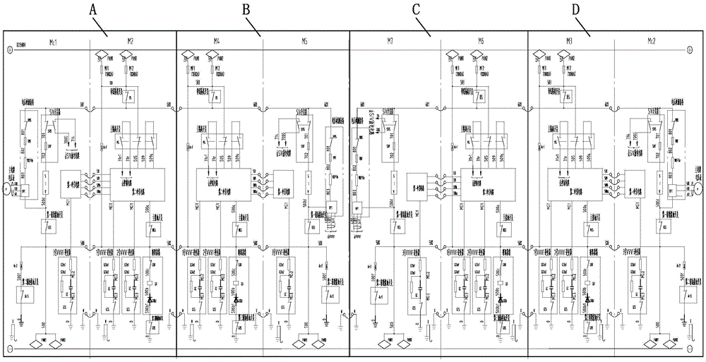
Fig. 1 is a schematic diagram of a first and second consist vehicle circuit provided by an embodiment of the present invention;
FIG. 2 is a schematic diagram of a according to an embodiment of the present invention;
FIG. 3 is a schematic diagram of a device B according to an embodiment of the present invention;
FIG. 4 is a schematic diagram of a step C according to an embodiment of the present invention;
FIG. 5 is a schematic view of a step D according to an embodiment of the present invention;
fig. 6 is a schematic diagram of a power supply control circuit according to an embodiment of the present invention;
FIG. 7 is a schematic diagram of an X according to an embodiment of the present invention;
FIG. 8 is a schematic view of a Y according to an embodiment of the present invention;
fig. 9 is a schematic view of Z according to an embodiment of the present invention.
Detailed Description
The technical solutions in the embodiments of the present invention will be clearly and completely described below with reference to the drawings in the embodiments of the present invention, and it is obvious that the described embodiments are only a part of the embodiments of the present invention, and not all of the embodiments. All other embodiments, which can be derived by a person skilled in the art from the embodiments given herein without making any creative effort, shall fall within the protection scope of the present invention.
The present embodiment will provide a straddle-type monorail vehicle control circuit, which, referring to fig. 1 to 9, includes:
the system comprises a first marshalling vehicle circuit, a second marshalling vehicle circuit and a power supply control circuit;
the first and second consist vehicle circuits are two mutually independent high voltage circuits;
when one of the first marshalling vehicle circuit and the second marshalling vehicle circuit has a fault, the power supply control circuit controls to realize the disconnection of the high-voltage power of the faulted marshalling vehicle circuit, and the non-faulted marshalling vehicle circuit provides the high-voltage power.
When the first marshalling vehicle circuit fails, for example, the control effects a high-voltage electrical disconnection of the first marshalling vehicle circuit, the second marshalling vehicle circuit providing a high-voltage electrical; when the second consist vehicle circuit fails, control effects a high voltage electrical disconnection of the second consist vehicle circuit, the first consist vehicle circuit providing a high voltage electrical.
The faults comprise IGBT breakdown, line contactor faults, GR faults, main loop current receiving faults, negative electrode poor contact and the like. The circuit with the fault cuts off the supply of high voltage electricity, and the secondary damage to the fault circuit caused by the high voltage current of the fault unit is avoided. A high voltage power is provided to the non-faulty marshalling vehicle circuit so that the non-faulty marshalling vehicle circuit can still function properly.
Through the scheme, the first marshalling vehicle circuit and the second marshalling vehicle circuit are two mutually independent high-voltage circuits, when one circuit breaks down, the broken-down marshalling vehicle circuit can be isolated, the un-broken-down marshalling vehicle circuit can still normally run, vehicle self-rescue is realized, a row of rescue vehicles are not required to be arranged to rescue the broken-down vehicle, and the vehicle rescue system has more effective rescue capacity and more flexible rescue mode and can complete vehicle rescue in a mode with the minimum influence on operation.
The vehicles can be evacuated near the platform, and the operation can be completed in the shortest time in a mode of folding empty vehicles at the terminal station back to the garage or entering an escape line.
Alternatively, when one of the first and second consist vehicle circuits fails, the high-voltage power of the first and second consist vehicle circuits is controlled to be completely disconnected by the power supply control circuit, and then the high-voltage power is supplied to the non-failed consist vehicle circuit.
For example, when the first marshalling vehicle circuit is in failure, the high-voltage electricity of the first marshalling vehicle circuit and the second marshalling vehicle circuit is disconnected, and then the high-voltage electricity is provided for the second marshalling vehicle circuit; when the second marshalling vehicle circuit breaks down, the high-voltage electricity of the first marshalling vehicle circuit and the second marshalling vehicle circuit is disconnected, and then the high-voltage electricity is provided for the first marshalling vehicle circuit.
Alternatively, the disconnection of the high voltage of the faulty marshalling vehicle circuit can also be effected by only disconnecting the high voltage of the faulty marshalling vehicle circuit, which provides the high voltage power.
Alternatively, the power supply control circuit is a pantograph control circuit, when one of the first and second vehicle composition circuits fails, all positive pole pantograph descending bows of the pantograph of the first and second vehicle composition circuits are controlled by the pantograph control circuit, so that the high-voltage power of the first and second vehicle composition circuits is completely cut off, and then the positive pole pantograph ascending bow of the pantograph of the vehicle composition circuit without failure is controlled, so that the high-voltage power is supplied to the vehicle composition circuit without failure. Namely, the anode bow of the non-failed marshalling vehicle circuit is independently subjected to current. After the fault operation is successful, the vehicle has the fault self-rescue operation capability and automatically operates back to the garage according to the line operation requirement.
Optionally, the first and second vehicle composition circuits correspond to 4 vehicle composition modes, that is, 4+4 vehicle composition modes, and there are 8 vehicles in total. The straddle type monorail train adopts a 4+4 marshalling mode of the train, such as a Chongqing third line, so that a vehicle rescue mode is more reliable, flexible and effective, and the rescue requirement of long marshalling vehicles can be met. In the third line extension project of Chongqing, when a row of 4+4 marshalling vehicles breaks down on a 50 ‰ slope, the vehicles can still run smoothly, and the self-rescue requirement of the 4+4 marshalling vehicles can be met; namely, the 4+4 marshalling mode vehicle has the rescue ability of realizing self rescue under 50 per mill extreme condition, and has reliable and effective rescue ability.
Optionally, the 4 vehicles corresponding to the first consist vehicle circuit are Mc1, M2, M4, M5, respectively, and the 4 vehicles corresponding to the second consist vehicle circuit are M7, M6, M3, Mc2, respectively; mc1, M2, M4, M5, M7, M6, M3, Mc2 are 8 vehicles from left to right; mc1, M2, M4 and M5 are sequentially vehicles 1 to 4, and M7, M6, M3 and Mc2 are sequentially vehicles 5 to 8; mc1, M5, M7 and Mc2 are connected with a negative pole bow; m2, M4, M6 and M3 are connected with the positive pole bow. The arrangement mode can reduce the whole volume of the vehicle. When a circuit corresponding to the vehicle Mc1 has a fault, all the positive electrode bows, namely the positive electrode bows of the vehicle Mc2, the vehicle M4, the vehicle M6 and the vehicle M3 are subjected to bow reduction to realize high-voltage power failure of the whole circuit, without processing due to the negative electrode bows connected with the vehicle Mc1, the vehicle M5, the vehicle M7 and the vehicle M2; and then raising the positive pole bow of the pantograph of the non-fault marshalling vehicle circuit, namely raising the positive pole bow of M6 and M3, namely selecting a raised 2 bow, so as to ensure that the non-fault marshalling vehicle can normally run. The positive electrode arches of M2 and M4 do not rise, so that secondary damage to a fault circuit caused by high-voltage current collection of a fault unit is avoided. The faulted marshalling vehicle circuit is still supplied with 380V medium-voltage alternating current and 110V emergency power supply, and can realize the functions of network monitoring, opening and closing of vehicle doors, starting and closing of air conditioners and the like.
Optionally, the circuits corresponding to Mc1, M5, M7, Mc2 each include: the system comprises voltage detection equipment, an SIV switch box, an SIV, a first auxiliary grounding switch, a second auxiliary grounding switch, a No. 3 VVVF inverter and a first traction circuit;
one ends of the voltage detection devices of the Mc1 and the M5 and one end of the SIV switch box are connected with a high-voltage current-receiving positive line of a first marshalling vehicle circuit, and one ends of the voltage detection devices of the M7 and the Mc2 and one end of the SIV switch box are connected with a high-voltage current-receiving positive line of a second marshalling vehicle circuit; the other end of the voltage detection device is connected with one end of a first auxiliary grounding switch, the other end of the SIV switch box is connected with one end of an SIV, and the other end of the SIV is connected with one end of the first auxiliary grounding switch;
the other ends of the first auxiliary grounding switches of Mc1 and M5 are connected with the high-voltage current-receiving negative line of the first marshalling vehicle circuit, and the other ends of the first auxiliary grounding switches of M7 and Mc2 are connected with the high-voltage current-receiving negative line of the second marshalling vehicle circuit;
both ends of the second auxiliary grounding switches of Mc1 and M5 are respectively grounded and connected with a high-voltage current-receiving negative line of the first marshalling vehicle circuit;
two ends of the second auxiliary grounding switches of the M7 and the Mc2 are grounded and connected with a high-voltage current-receiving negative line of a second marshalling vehicle circuit respectively;
the two ends of the No. 3 VVVF inverter are respectively grounded and connected with one end of a first traction circuit, the other end of the first traction circuit of Mc1 is connected with one end of a second traction circuit of M2, the other end of the first traction circuit of M5 is connected with one end of the second traction circuit of M4, the other end of the first traction circuit of M7 is connected with one end of the second traction circuit of M6, and the other end of the first traction circuit of Mc2 is connected with one end of the second traction circuit of M3;
the circuits corresponding to M2, M4, M6 and M3 all comprise: the system comprises a main isolating switch, a third auxiliary grounding switch, a main grounding switch, a No. 1 VVVF inverter, a No. 2 VVF inverter, a second traction circuit and a breaker box;
one end of the female disconnecting switch of M2 and M4 is connected with the high-voltage current-receiving positive line of the first marshalling vehicle circuit, and one end of the female disconnecting switch of M6 and M3 is connected with the high-voltage current-receiving positive line of the second marshalling vehicle circuit; the other end of the main isolating switch is connected with one end of the main isolating switch, the other end of the main isolating switch is connected with a second traction circuit, the second traction circuit is also respectively connected with a main grounding switch, a No. 1 VVVF inverter and a No. 2 VVF inverter, and the No. 1 VVF inverter and the No. 2 VVF inverter are also respectively grounded;
the main grounding switches and the breaker boxes of the M2 and the M4 are connected with a high-voltage current-receiving negative line of a first marshalling vehicle circuit, and the main grounding switches and the breaker boxes of the M6 and the M3 are connected with a high-voltage current-receiving negative line of a second marshalling vehicle circuit;
and two ends of the third auxiliary grounding switch are respectively grounded and connected with the breaker box.
The high voltage current receiving positive line is also indicated by the line number 601 in the figure; the high voltage current negative line is also shown as line number 500; as can be seen from the figure, the positive DC1500V line (i.e., line number 601) and the negative DC1500V line (i.e., line number 500) between the M5 vehicle and the M7 vehicle do not directly penetrate, so that the vehicles 1 to 4 and the vehicles 5 to 8 form two independent high-voltage main circuit units, respectively.
Optionally, the pantograph control circuit comprises corresponding circuits for controlling Mc1, M2, M4, M5, M7, M6, M3, Mc 2;
the circuits corresponding to Mc1 and Mc2 respectively comprise SIVN, PanN, PanDS, PanUS1, HCR6, a pantograph selection circuit and SIV; one end of the SIVN and one end of the PanN are both connected with a direct-current voltage (namely 110V), the other end of the SIVN is connected with a first port of the SIV, the other end of the PanN is respectively connected with one end of PanDS and one end of PanUS1, the other end of the PanDS is connected with a line number 262, and the other end of the PanUS1 is respectively connected with two ports of the pantograph selection circuit; the other two ports of the pantograph selection circuit are respectively connected with a line number 261a and a line number 261 b; the second port of the SIV is connected to line number 262; the first port and the third port of the SIV of Mc1 are communicated through a GR switch and a line number 202a in the circuit corresponding to the line numbers 202 and M2 respectively; the first port and the third port of the SIV of Mc2 are communicated through a GR switch and a line number 202a in the circuit corresponding to the line numbers 202 and M3 respectively;
the circuits corresponding to M5 and M7 respectively comprise SIVN and SIV; one end of the SIVN is connected with the direct-current voltage, the other end of the SIVN is connected with a first port of the SIV, and a second port of the SIV is connected with a line number 262; the first port and the third port of the SIV of M5 are communicated through a GR switch and a line number 202a in the circuit corresponding to the line numbers 202 and M4 in sequence; the first port and the third port of the SIV of M7 are communicated through a GR switch and a line number 202a in the circuit corresponding to the line numbers 202 and M6 in sequence;
the circuits corresponding to M2, M4, M6 and M3 respectively comprise PanKN, PanUK, PanUM1, PanUM2, PanDMV1, PanDMV2, LGS switch, first switch, second switch and third switch; one end of PanKN is connected with direct-current voltage, the other end of PanKN is connected with one end of a first switch, the other end of the first switch is respectively connected with the third end of PanUK and one end of a second switch, the other end of the second switch is respectively connected with the third end of PanUK, one end of PanUM1 and one end of PanUM2, the other end of PanUM1 and the other end of PanUM2 are both connected with one end of a third switch, the other end of the third switch is respectively connected with the third end of PanUK and an LGS switch, and the LGS switch is also grounded; the first end and the second end of panKN are respectively connected with a line number 261a and an LGS switch; one end of PanDMV1 and one end of PanDMV2 are both connected to line number 262b, and the other end of PanDMV1 and the other end of PanDMV2 are both connected to an LGS switch.
Alternatively, the first and second consist vehicle circuits are two mutually independent high voltage circuits by disconnecting the high voltage current-receiving positive line of the first consist vehicle circuit from the high voltage current-receiving positive line of the second consist vehicle circuit and disconnecting the high voltage current-receiving negative line of the first consist vehicle circuit from the high voltage current-receiving negative line of the second consist vehicle circuit.
Optionally, the first and second consist vehicle circuits are each 1500 volts.
Optionally, the voltage of the power supply control circuit is 110 volts.
Optionally, the faulty marshalling vehicle circuit, still supplied with 380 v medium voltage ac and 110v emergency power, may implement network monitoring, door opening and closing, air conditioner starting and closing, etc.
The embodiment also provides a straddle type monorail vehicle which comprises the straddle type monorail vehicle control circuit.
The foregoing is only a preferred embodiment of the present invention, and it should be noted that, for those skilled in the art, various modifications and additions can be made without departing from the principle of the present invention, and these should also be considered as the protection scope of the present invention.

Claims (10)

1.一种跨座式单轨车辆控制电路,其特征在于,包括:1. A straddle type monorail vehicle control circuit is characterized in that, comprising: 第一编组车辆电路、第二编组车辆电路、供电控制电路;The first grouping vehicle circuit, the second grouping vehicle circuit, the power supply control circuit; 所述第一编组车辆电路和所述第二编组车辆电路是两个相互独立的高压电路;The first group vehicle circuit and the second group vehicle circuit are two independent high-voltage circuits; 所述第一编组车辆电路、所述第二编组车辆电路中的其中一个出现故障时,通过所述供电控制电路,控制实现出现故障的编组车辆电路的高压电的断开,未出现故障的编组车辆电路提供高压电。When one of the first marshalling vehicle circuit and the second marshalling vehicle circuit fails, the power supply control circuit controls and realizes the disconnection of the high-voltage power of the faulty marshalling vehicle circuit, and the failure occurs. The marshalling vehicle circuit provides high voltage electricity. 2.根据权利要求1所述的跨座式单轨车辆控制电路,其特征在于,所述第一编组车辆电路、所述第二编组车辆电路中的其中一个出现故障时,通过所述供电控制电路,控制所述第一编组车辆电路、所述第二编组车辆电路的高压电全部断开,然后给未出现故障的编组车辆电路提供高压电。2 . The straddle-type monorail vehicle control circuit according to claim 1 , wherein when one of the first group vehicle circuit and the second group vehicle circuit fails, the power supply control circuit is passed through the power supply control circuit. 3 . , control the high-voltage power of the first group vehicle circuit and the second group vehicle circuit to be all disconnected, and then provide high-voltage power to the non-faulty group vehicle circuit. 3.根据权利要求2所述的跨座式单轨车辆控制电路,其特征在于,所述供电控制电路为受电弓控制电路,所述第一编组车辆电路、所述第二编组车辆电路中的其中一个出现故障时,通过所述受电弓控制电路,控制所述第一编组车辆电路、所述第二编组车辆电路的受电弓的所有正极弓降弓,实现所述第一编组车辆电路、所述第二编组车辆电路的高压电全部断开,然后控制未出现故障的编组车辆电路的受电弓的正极弓升弓,实现给未出现故障的编组车辆电路提供高压电。3 . The straddle type monorail vehicle control circuit according to claim 2 , wherein the power supply control circuit is a pantograph control circuit, and the circuit of the first grouped vehicle and the circuit of the second grouped vehicle are 3 . When one of them fails, the pantograph control circuit controls all the positive bows of the pantographs of the first group of vehicle circuits and the second group of vehicle circuits to drop bows, so as to realize the first group of vehicle circuits , The high voltage power of the second marshalling vehicle circuit is all disconnected, and then the positive bow of the pantograph of the unfaulted marshalling vehicle circuit is controlled to provide high voltage power to the unfaulted marshalling vehicle circuit. 4.根据权利要求3所述的跨座式单轨车辆控制电路,其特征在于,所述第一编组车辆电路、所述第二编组车辆电路均对应4编组模式的车辆。4 . The straddle-type monorail vehicle control circuit according to claim 3 , wherein the first composition vehicle circuit and the second composition vehicle circuit both correspond to vehicles in a 4 composition mode. 5 . 5.根据权利要求4所述的跨座式单轨车辆控制电路,其特征在于,所述第一编组车辆电路对应的4个车辆分别为Mc1、M2、M4、M5,所述第二编组车辆电路对应的4个车辆分别为M7、M6、M3、Mc2;所述Mc1、所述M2、所述M4、所述M5、所述M7、所述M6、所述M3、所述Mc2为从左至右的8个车辆;所述Mc1、所述M5、所述M7、所述Mc2接负极弓;所述M2、所述M4、所述M6、所述M3接正极弓。5 . The straddle-type monorail vehicle control circuit according to claim 4 , wherein the four vehicles corresponding to the first grouping vehicle circuit are Mc1 , M2 , M4 , and M5 respectively, and the second grouping vehicle circuit The corresponding 4 vehicles are M7, M6, M3, Mc2; the Mc1, the M2, the M4, the M5, the M7, the M6, the M3, and the Mc2 are from left to The 8 vehicles on the right; the Mc1, the M5, the M7, and the Mc2 are connected to the negative bow; the M2, the M4, the M6, and the M3 are connected to the positive bow. 6.根据权利要求5所述的跨座式单轨车辆控制电路,其特征在于,所述Mc1、所述M5、所述M7、所述Mc2对应的电路均包括:电压检测设备、SIV开关箱、SIV、第一辅助接地开关、第二辅助接地开关、3号VVVF逆变器、第一牵引电路;6 . The straddle type monorail vehicle control circuit according to claim 5 , wherein the circuits corresponding to the Mc1 , the M5 , the M7 , and the Mc2 all comprise: a voltage detection device, a SIV switch box, SIV, the first auxiliary grounding switch, the second auxiliary grounding switch, the No. 3 VVVF inverter, the first traction circuit; 所述Mc1和所述M5的所述电压检测设备的一端、所述SIV开关箱的一端均与所述第一编组车辆电路的高压受流正线连接,所述M7和所述Mc2的所述电压检测设备的一端、所述SIV开关箱的一端均与所述第二编组车辆电路的高压受流正线连接;所述电压检测设备的另一端与所述第一辅助接地开关的一端连接,所述SIV开关箱的另一端与所述SIV的一端连接,所述SIV的另一端与所述第一辅助接地开关的一端连接;One end of the voltage detection device of the Mc1 and the M5, and one end of the SIV switch box are all connected to the high-voltage current-receiving positive line of the first grouping vehicle circuit, and the M7 and the Mc2 One end of the voltage detection device and one end of the SIV switch box are connected to the high-voltage current receiving positive line of the second grouped vehicle circuit; the other end of the voltage detection device is connected to one end of the first auxiliary grounding switch, The other end of the SIV switch box is connected to one end of the SIV, and the other end of the SIV is connected to one end of the first auxiliary grounding switch; 所述Mc1和所述M5的所述第一辅助接地开关的另一端、与所述第一编组车辆电路的高压受流负线连接,所述M7和所述Mc2的所述第一辅助接地开关的另一端、与所述第二编组车辆电路的高压受流负线连接;The other ends of the first auxiliary grounding switches of the Mc1 and the M5 are connected to the high-voltage current-receiving negative line of the first group vehicle circuit, and the first auxiliary grounding switches of the M7 and the Mc2 The other end of the vehicle is connected to the high-voltage current-receiving negative line of the second grouping vehicle circuit; 所述Mc1和所述M5的所述第二辅助接地开关的两端分别接地、接所述第一编组车辆电路的高压受流负线;Both ends of the second auxiliary grounding switch of the Mc1 and the M5 are respectively grounded and connected to the high-voltage current-receiving negative line of the first grouping vehicle circuit; 所述M7和所述Mc2的所述第二辅助接地开关的两端分别接地、接所述第二编组车辆电路的高压受流负线;Both ends of the second auxiliary grounding switch of the M7 and the Mc2 are respectively grounded and connected to the high-voltage current-receiving negative line of the second grouping vehicle circuit; 所述3号VVVF逆变器的两端分别接地、接所述第一牵引电路的一端,所述Mc1的所述第一牵引电路的另一端与所述M2的第二牵引电路的一端连接,所述M5的所述第一牵引电路的另一端与所述M4的所述第二牵引电路的一端连接,所述M7的所述第一牵引电路的另一端与所述M6的所述第二牵引电路的一端连接,所述Mc2的所述第一牵引电路的另一端与所述M3的所述第二牵引电路的一端连接;The two ends of the No. 3 VVVF inverter are respectively grounded and connected to one end of the first traction circuit, and the other end of the first traction circuit of Mc1 is connected to one end of the second traction circuit of M2, The other end of the first pulling circuit of the M5 is connected to one end of the second pulling circuit of the M4, and the other end of the first pulling circuit of the M7 is connected to the second pulling circuit of the M6. One end of the pulling circuit is connected, and the other end of the first pulling circuit of the Mc2 is connected to one end of the second pulling circuit of the M3; 所述M2、所述M4、所述M6、所述M3对应的电路均包括:母隔离开关、主隔离开关、第三辅助接地开关、主接地开关、1号VVVF逆变器、2号VVVF逆变器、所述第二牵引电路、断路器箱;The circuits corresponding to the M2, the M4, the M6, and the M3 include: a main isolation switch, a main isolation switch, a third auxiliary grounding switch, a main grounding switch, the No. 1 VVVF inverter, and the No. 2 VVVF inverter. The inverter, the second traction circuit, the circuit breaker box; 所述M2和所述M4的所述母隔离开关的一端与所述第一编组车辆电路的高压受流正线连接,所述M6和所述M3的所述母隔离开关的一端与所述第二编组车辆电路的高压受流正线连接;所述母隔离开关的另一端与所述主隔离开关的一端连接,所述主隔离开关的另一端与所述第二牵引电路连接,所述第二牵引电路还分别与所述主接地开关、所述1号VVVF逆变器、所述2号VVVF逆变器连接,所述1号VVVF逆变器、所述2号VVVF逆变器还分别接地;One end of the mother isolation switch of the M2 and the M4 is connected to the high-voltage current receiving positive line of the first grouped vehicle circuit, and one end of the mother isolation switch of the M6 and the M3 is connected to the first group. The high-voltage current-receiving positive line of the two-group vehicle circuit is connected; the other end of the main disconnecting switch is connected to one end of the main disconnecting switch, the other end of the main disconnecting switch is connected to the second traction circuit, and the second The second traction circuit is also connected to the main grounding switch, the No. 1 VVVF inverter, and the No. 2 VVVF inverter, respectively, and the No. 1 VVVF inverter and the No. 2 VVVF inverter are also respectively ground; 所述M2和所述M4的所述主接地开关、所述断路器箱均与所述第一编组车辆电路的高压受流负线连接,所述M6和所述M3的所述主接地开关、所述断路器箱均与所述第二编组车辆电路的高压受流负线连接;The main grounding switches and the circuit breaker boxes of the M2 and M4 are all connected to the high-voltage current-receiving negative line of the vehicle circuit of the first group, and the main grounding switches, the M6 and the M3 The circuit breaker boxes are all connected with the high-voltage current-receiving negative lines of the second grouping vehicle circuit; 所述第三辅助接地开关的两端分别接地和所述断路器箱。Both ends of the third auxiliary grounding switch are grounded to the circuit breaker box, respectively. 7.根据权利要求5所述的跨座式单轨车辆控制电路,其特征在于,所述受电弓控制电路包括控制所述Mc1、所述M2、所述M4、所述M5、所述M7、所述M6、所述M3、所述Mc2对应的电路;7 . The straddle type monorail vehicle control circuit according to claim 5 , wherein the pantograph control circuit includes controlling the Mc1 , the M2 , the M4 , the M5 , the M7 , the Circuits corresponding to the M6, the M3, and the Mc2; 所述Mc1、所述Mc2对应的电路均包括SIVN、PanN、PanDS、PanUS1、HCR6、受电弓选择电路、SIV;所述SIVN的一端、所述PanN的一端均与直流电压连接,所述SIVN的另一端与所述SIV的第一端口连接,所述PanN的另一端分别与所述PanDS的一端、所述PanUS1的一端连接,所述PanDS的另一端与线号262连接,所述PanUS1的另一端分别与所述受电弓选择电路的两个端口连接;所述受电弓选择电路的另两个端口分别与线号261a、线号261b连接;所述SIV的第二端口与所述线号262连接;所述Mc1的所述SIV的第一端口、第三端口依次通过线号202、所述M2对应的电路中的GR开关、线号202a连通;所述Mc2的所述SIV的第一端口、第三端口依次通过线号202、所述M3对应的电路中的GR开关、线号202a连通;The circuits corresponding to the Mc1 and the Mc2 include SIVN, PanN, PanDS, PanUS1, HCR6, a pantograph selection circuit, and SIV; one end of the SIVN and one end of the PanN are connected to a DC voltage, and the SIVN The other end of the PanN is connected to the first port of the SIV, the other end of the PanN is respectively connected to one end of the PanDS and one end of the PanUS1, the other end of the PanDS is connected to the line number 262, the PanUS1 The other end is respectively connected with the two ports of the pantograph selection circuit; the other two ports of the pantograph selection circuit are respectively connected with the line number 261a and the line number 261b; the second port of the SIV is connected with the The line number 262 is connected; the first port and the third port of the SIV of the Mc1 are sequentially connected through the line number 202, the GR switch in the circuit corresponding to the M2, and the line number 202a; the SIV of the Mc2 is connected The first port and the third port are sequentially connected through the line number 202, the GR switch in the circuit corresponding to the M3, and the line number 202a; 所述M5、所述M7对应的电路均包括SIVN、SIV;所述SIVN的一端与所述直流电压连接,所述SIVN的另一端与所述SIV的第一端口连接,所述SIV的第二端口与所述线号262连接;所述M5的所述SIV的第一端口、第三端口依次通过线号202、所述M4对应的电路中的GR开关、线号202a连通;所述M7的所述SIV的第一端口、第三端口依次通过线号202、所述M6对应的电路中的GR开关、线号202a连通;The circuits corresponding to the M5 and the M7 include SIVN and SIV; one end of the SIVN is connected to the DC voltage, the other end of the SIVN is connected to the first port of the SIV, and the second end of the SIV is connected to the first port of the SIV. The port is connected to the line number 262; the first port and the third port of the SIV of the M5 are sequentially connected through the line number 202, the GR switch in the circuit corresponding to the M4, and the line number 202a; the M7 The first port and the third port of the SIV are sequentially connected through the line number 202, the GR switch in the circuit corresponding to the M6, and the line number 202a; 所述M2、所述M4、所述M6、所述M3对应的电路均包括PanKN、PanUK、PanUM1、PanUM2、PanDMV1、PanDMV2、LGS开关、第一开关、第二开关、第三开关;所述PanKN的一端与所述直流电压连接,所述PanKN的另一端与所述第一开关的一端连接,所述第一开关的另一端分别与所述PanUK的第三端、所述第二开关的一端连接,所述第二开关的另一端分别与所述PanUK的第三端、所述PanUM1的一端、所述PanUM2的一端连接,所述PanUM1的另一端、所述PanUM2的另一端均与所述第三开关的一端连接,所述第三开关的另一端分别与所述PanUK的第三端、所述LGS开关连接,所述LGS开关还接地;所述PanKN的第一端和第二端分别与所述线号261a、所述LGS开关连接;所述PanDMV1的一端、所述PanDMV2的一端均与线号262b连接,所述PanDMV1的另一端、所述PanDMV2的另一端均与所述LGS开关连接。The circuits corresponding to the M2, the M4, the M6, and the M3 all include PanKN, PanUK, PanUM1, PanUM2, PanDMV1, PanDMV2, LGS switch, first switch, second switch, and third switch; the PanKN One end of the PanKN is connected to the DC voltage, the other end of the PanKN is connected to one end of the first switch, and the other end of the first switch is respectively connected to the third end of the PanUK and one end of the second switch connection, the other end of the second switch is respectively connected to the third end of the PanUK, one end of the PanUM1, and one end of the PanUM2, and the other end of the PanUM1 and the other end of the PanUM2 are connected to the One end of the third switch is connected, and the other end of the third switch is respectively connected to the third end of the PanUK and the LGS switch, and the LGS switch is also grounded; the first end and the second end of the PanKN are respectively Connect to the line number 261a and the LGS switch; one end of the PanDMV1 and one end of the PanDMV2 are connected to the line number 262b, and the other end of the PanDMV1 and the other end of the PanDMV2 are connected to the LGS switch connect. 8.根据权利要求1至7任一项所述的跨座式单轨车辆控制电路,其特征在于,通过所述第一编组车辆电路的高压受流正线与所述第二编组车辆电路的高压受流正线不连接,所述第一编组车辆电路的高压受流负线与所述第二编组车辆电路的高压受流负线不连接的方式,实现所述第一编组车辆电路和所述第二编组车辆电路是两个相互独立的高压电路。8. The straddle-type monorail vehicle control circuit according to any one of claims 1 to 7, wherein the high-voltage current-receiving positive line of the first grouping vehicle circuit and the high-voltage current of the second grouping vehicle circuit pass through The current-receiving positive line is not connected, and the high-voltage current-receiving negative line of the first grouping vehicle circuit is not connected to the high-voltage current-receiving negative line of the second grouping vehicle circuit. The second group of vehicle circuits are two independent high voltage circuits. 9.根据权利要求1至7任一项所述的跨座式单轨车辆控制电路,其特征在于,所述第一编组车辆电路和所述第二编组车辆电路的电压均为1500伏。9 . The straddle-type monorail vehicle control circuit according to claim 1 , wherein the voltages of the first group vehicle circuit and the second group vehicle circuit are both 1500 volts. 10 . 10.一种跨座式单轨车辆,其特征在于,包括如权利要求1至9任一项所述的跨座式单轨车辆控制电路。10. A straddle-type monorail vehicle, characterized by comprising the straddle-type monorail vehicle control circuit according to any one of claims 1 to 9.
CN201911212543.9A 2019-12-02 2019-12-02 A straddle type monorail vehicle control circuit and straddle type monorail vehicle Active CN110901398B (en)

Priority Applications (2)

Application Number Priority Date Filing Date Title
CN201911212543.9A CN110901398B (en) 2019-12-02 2019-12-02 A straddle type monorail vehicle control circuit and straddle type monorail vehicle
CN202110282081.9A CN112977482B (en) 2019-12-02 2019-12-02 Straddle type monorail vehicle

Applications Claiming Priority (1)

Application Number Priority Date Filing Date Title
CN201911212543.9A CN110901398B (en) 2019-12-02 2019-12-02 A straddle type monorail vehicle control circuit and straddle type monorail vehicle

Related Child Applications (1)

Application Number Title Priority Date Filing Date
CN202110282081.9A Division CN112977482B (en) 2019-12-02 2019-12-02 Straddle type monorail vehicle

Publications (2)

Publication Number Publication Date
CN110901398A true CN110901398A (en) 2020-03-24
CN110901398B CN110901398B (en) 2021-03-23

Family

ID=69821281

Family Applications (2)

Application Number Title Priority Date Filing Date
CN201911212543.9A Active CN110901398B (en) 2019-12-02 2019-12-02 A straddle type monorail vehicle control circuit and straddle type monorail vehicle
CN202110282081.9A Active CN112977482B (en) 2019-12-02 2019-12-02 Straddle type monorail vehicle

Family Applications After (1)

Application Number Title Priority Date Filing Date
CN202110282081.9A Active CN112977482B (en) 2019-12-02 2019-12-02 Straddle type monorail vehicle

Country Status (1)

Country Link
CN (2) CN110901398B (en)

Cited By (2)

* Cited by examiner, † Cited by third party
Publication number Priority date Publication date Assignee Title
CN113771630A (en) * 2021-09-24 2021-12-10 中车长春轨道客车股份有限公司 Ground protection circuit for urban railway vehicle
WO2022088340A1 (en) * 2020-10-30 2022-05-05 中车大连电力牵引研发中心有限公司 High-voltage system topological structure of air rail vehicle

Families Citing this family (1)

* Cited by examiner, † Cited by third party
Publication number Priority date Publication date Assignee Title
CN116022175B (en) * 2023-02-10 2026-03-17 中车长春轨道客车股份有限公司 A city-area A-type vehicle topology structure that enables flexible grouping

Citations (6)

* Cited by examiner, † Cited by third party
Publication number Priority date Publication date Assignee Title
CN102381198A (en) * 2011-11-29 2012-03-21 南车株洲电力机车有限公司 High-voltage circuit for electric locomotive unit
CN103395377A (en) * 2013-06-24 2013-11-20 南车株洲电力机车有限公司 Main cutting-off circuit of electric locomotive set and main cutting-off control method
KR101359414B1 (en) * 2013-04-23 2014-02-10 엔텍월드(주) The integrated single phase power supply system for electric railway
CN106515458A (en) * 2016-12-08 2017-03-22 中车株洲电力机车有限公司 Method and system for controlling high-voltage isolating switches of electric locomotive group
CN109572434A (en) * 2018-12-05 2019-04-05 中车长春轨道客车股份有限公司 Pressure exchange extension power-supply system and method in a kind of long marshaling
CN109720357A (en) * 2017-10-26 2019-05-07 株洲中车时代电气股份有限公司 A kind of high pressure reconnection control system and method

Family Cites Families (5)

* Cited by examiner, † Cited by third party
Publication number Priority date Publication date Assignee Title
CN203391776U (en) * 2013-06-29 2014-01-15 南车南京浦镇车辆有限公司 Multi-train electrical reconnection control circuit of motor train unit
CN106379339B (en) * 2016-09-30 2018-12-11 株洲中车时代电气股份有限公司 For realizing the device and method for the reconnection control circuit that locomotive wirelessly joins again
CN206367387U (en) * 2016-10-31 2017-08-01 中车株洲电力机车有限公司 A kind of city rail vehicle power supply circuit and city rail vehicle
CN108572574B (en) * 2018-05-18 2020-11-27 中车株洲电力机车有限公司 A high-voltage grid-side circuit of a power vehicle in an EMU and its control method
CN109638809B (en) * 2018-12-05 2023-05-23 中车长春轨道客车股份有限公司 Low-voltage direct-current expansion power supply system and method for long marshalling train

Patent Citations (6)

* Cited by examiner, † Cited by third party
Publication number Priority date Publication date Assignee Title
CN102381198A (en) * 2011-11-29 2012-03-21 南车株洲电力机车有限公司 High-voltage circuit for electric locomotive unit
KR101359414B1 (en) * 2013-04-23 2014-02-10 엔텍월드(주) The integrated single phase power supply system for electric railway
CN103395377A (en) * 2013-06-24 2013-11-20 南车株洲电力机车有限公司 Main cutting-off circuit of electric locomotive set and main cutting-off control method
CN106515458A (en) * 2016-12-08 2017-03-22 中车株洲电力机车有限公司 Method and system for controlling high-voltage isolating switches of electric locomotive group
CN109720357A (en) * 2017-10-26 2019-05-07 株洲中车时代电气股份有限公司 A kind of high pressure reconnection control system and method
CN109572434A (en) * 2018-12-05 2019-04-05 中车长春轨道客车股份有限公司 Pressure exchange extension power-supply system and method in a kind of long marshaling

Cited By (3)

* Cited by examiner, † Cited by third party
Publication number Priority date Publication date Assignee Title
WO2022088340A1 (en) * 2020-10-30 2022-05-05 中车大连电力牵引研发中心有限公司 High-voltage system topological structure of air rail vehicle
CN113771630A (en) * 2021-09-24 2021-12-10 中车长春轨道客车股份有限公司 Ground protection circuit for urban railway vehicle
CN113771630B (en) * 2021-09-24 2023-08-25 中车长春轨道客车股份有限公司 Urban railway vehicle grounding protection circuit

Also Published As

Publication number Publication date
CN112977482B (en) 2022-06-21
CN110901398B (en) 2021-03-23
CN112977482A (en) 2021-06-18

Similar Documents

Publication Publication Date Title
CN105305620B (en) A kind of breaker closing control loop template monitoring system
CN102424004A (en) Motor train unit network side circuit and control method thereof
CN110901398B (en) A straddle type monorail vehicle control circuit and straddle type monorail vehicle
EP3922502A1 (en) Rail transit train and fault protection method thereof
US8014178B2 (en) Converter station
CN116252627A (en) Electric vehicle high voltage power distribution system and electric vehicle
CN112297963B (en) Train high-voltage system and train
CN110098602A (en) A kind of Guangdong power system isolating device and method
CN109927574A (en) A kind of urban rail car main circuit
AU2016304615B2 (en) Ground protection method for main circuit of DC electric drive diesel locomotive
EP4653241A1 (en) Electric vehicle
CN113954641B (en) Urban rail train high voltage bus circuit
CN204290471U (en) Batteries off-line electric discharge free of discontinuities switching device shifter
CN206364435U (en) GIS buses standby spacing does not have a power failure enlarging functional module
CN205601632U (en) Redundant circuit system of electric locomotive high pressure is kept apart to disconnected nature of two owners
CN110293846B (en) Method, system and train for controlling AC bus contactor of train
CN202264649U (en) Network side circuit of motor train unit
CN110661331A (en) AC-DC converter
CN223778199U (en) Tram circuit structure
CN111907356A (en) Tramcar line power supply system
CN219697303U (en) Bus residual voltage temporary electricity holding device
CN223428204U (en) Automatic switching device for power supply
KR101410772B1 (en) Control circuit for high voltage of rail car
CN114604141B (en) A kind of bilateral penetrating in-phase power supply system and control method
CN214450313U (en) High-voltage bus structure of urban rail vehicle

Legal Events

Date Code Title Description
PB01 Publication
PB01 Publication
SE01 Entry into force of request for substantive examination
GR01 Patent grant
GR01 Patent grant