Disclosure of Invention
The invention aims to overcome the defects that the energy recovery rate of a braking energy recovery system is limited, the risk in the aspect of failure safety is easy to generate and the like in the prior art, and provides a braking energy recovery control method.
The invention solves the technical problems through the following technical scheme:
the braking energy recovery control method is characterized by being based on an electronic braking booster and an energy accumulator, wherein the electronic braking booster comprises a driver braking intention recognition module, a foot feel compensation module, an electro-hydraulic braking distribution module, a hydraulic control module and state managementA module comprising the steps of: step S1The driver steps on the brake pedal;
step S2The brake hydraulic pressure requested by the driver is transmitted to the foot feeling compensation module;
step S3The electro-hydraulic brake distribution module receives a brake torque requested by a driver and a pedal force compensation capacity value;
step S4The hydraulic control module controls the energy accumulator to enable actual hydraulic pressure in a brake loop to meet target hydraulic pressure calculated by the electro-hydraulic brake distribution module;
step S5And the state management module receives states of a pedal push rod position, a transmission gear, an ABS/ESC (anti-lock braking system/electronic stability control system), a vehicle speed and the like, and judges whether braking energy recovery can be executed or not under the current vehicle state.
According to an embodiment of the invention, said step S1Further comprising: the driver braking intention recognition module starts to work, takes a signal transmitted by the pedal push rod displacement sensor as an input, and obtains the corresponding braking hydraulic pressure requested by the driver according to the PV (pressure volume) characteristic of the braking system.
According to an embodiment of the invention, said step S1Further comprising: and calculating the braking torque requested by the driver according to the parameters of the whole vehicle and the parameters of the braking system.
According to an embodiment of the invention, said step S2Further comprising: and adjusting the assistance of the motor according to the master cylinder hydraulic pressure and the actual master cylinder hydraulic pressure, and outputting a pedal force compensation capability value.
According to an embodiment of the invention, said step S3Further comprising: according to the actual motor braking value and the motor braking capacity, the motor braking torque and the hydraulic braking torque in the current state are respectively judged, signals are respectively transmitted to the whole vehicle controller, motor braking is achieved, and the hydraulic control module achieves hydraulic braking control.
According to an embodiment of the invention, said step S4The liquid ofAnd an actuator of the pressure control module is an energy accumulator, and a hydraulic closed-loop control strategy is used.
According to an embodiment of the invention, said step S5Further comprising: and if energy recovery is required, transmitting the energy recovery function state to the electro-hydraulic brake distribution module, judging the motor braking torque and the hydraulic braking torque in the current state, and transmitting a signal to the foot feel compensation module.
According to one embodiment of the invention, the steady state balance relationship existing in the electronic brake booster throughout braking is: the brake pedal push rod force and the motor assisting force are equal to the master cylinder hydraulic pressure and the spring force.
According to one embodiment of the invention, the state management module is used for judging whether the braking energy recovery function can be executed under the current vehicle state, the control logic of the state management module is completed in the electric control processing unit, and the vehicle electric control unit acquires the signal related to the vehicle state.
According to an embodiment of the present invention, the method for controlling the state management module includes: when the function of ABS/ESC (anti-lock braking system/electronic stability control system) is triggered, the braking energy is not recovered again in consideration of safety, the motor is braked to exit, and the hydraulic braking is used for taking over;
when the pedal treading speed of the driver exceeds a certain threshold value, the emergency braking is considered, and the braking energy recovery is not carried out;
when the vehicle speed is lower than a certain threshold value, the braking energy is not recovered;
for safety reasons, no braking energy recovery is carried out when reversing.
The positive progress effects of the invention are as follows:
the braking energy recovery control method is based on the electronic brake booster and the energy accumulator, changes the traditional braking system, can realize the compensation of the hydraulic brake on the motor brake in the energy recovery process by coordinately controlling the electronic brake booster and the energy accumulator, ensures the braking efficiency of the whole vehicle, realizes the smooth conversion from the motor brake to the hydraulic brake under the condition that a driver does not perceive, can achieve the maximum motor brake of 0.3g, and has higher braking energy recovery rate. Meanwhile, the braking energy recovery control method is a non-decoupling scheme, and the risk in the aspect of failure safety is low.
Detailed Description
In order to make the aforementioned objects, features and advantages of the present invention comprehensible, embodiments accompanied with figures are described in detail below.
Embodiments of the present invention will now be described in detail with reference to the accompanying drawings. Reference will now be made in detail to the preferred embodiments of the present invention, examples of which are illustrated in the accompanying drawings. Wherever possible, the same reference numbers will be used throughout the drawings to refer to the same or like parts.
Further, although the terms used in the present invention are selected from publicly known and used terms, some of the terms mentioned in the description of the present invention may be selected by the applicant at his or her discretion, the detailed meanings of which are described in relevant parts of the description herein.
Furthermore, it is required that the present invention is understood, not simply by the actual terms used but by the meaning of each term lying within.
FIG. 1 is a schematic diagram of the connection between an electronic brake booster and an accumulator and the related interface in the braking energy recovery control method according to the present invention. FIG. 2 is a flow chart of a braking energy recovery control method according to the present invention. FIG. 3 is a graph showing the relationship between pedal push rod displacement and push rod force, and between pedal push rod displacement and spring force in the braking energy recovery control method of the present invention.
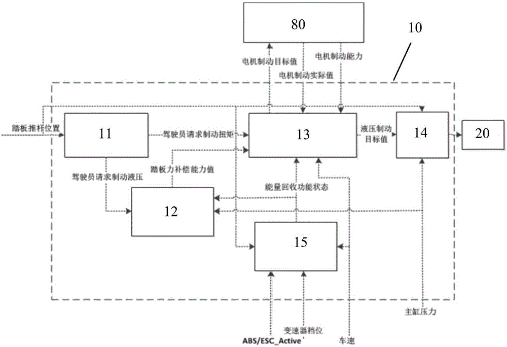
As shown in fig. 1 to 3, the present invention discloses a braking energy recovery control method based on an electric brake booster and an accumulator. During the braking energy recovery process, the electronic brake booster 10 includes a driver braking intention recognition module 11, a foot feel compensation module 12, an electro-hydraulic brake distribution module 13, a hydraulic control module 14 and a state management module 15. The accumulator 20 mainly functions to perform a corresponding command for controlling the amount of brake fluid sucked or discharged according to a target pressure calculated by the electronic brake booster, thereby adjusting hydraulic braking.
The electronic brake booster 10 is connected to the brake pedal 30, and when the driver steps on the brake pedal 30, the pedal push rod displacement sensor 40 will collect a displacement signal to the first electronic control processing unit 16 for analyzing the braking intention of the driver. The first motor 17 is then controlled to drive the first transmission mechanism 18 to push the master cylinder 50, so that the brake fluid in the master cylinder 50 enters the wheel cylinder 70 through the electronic stability control unit 60, and the hydraulic pressure is built.
When the braking energy is recovered, the motor brake replaces the hydraulic brake, and the brake fluid is introduced from the master cylinder 50 to the accumulator 20, and no brake fluid flows into the electronic stability control unit 60 and the wheel cylinder 70, so that no hydraulic pressure is generated. The method introduced here is: the second electric control processing unit 21 controls the second motor 22 to drive the second transmission mechanism 23, so that the volume of the hydraulic chamber 24 of the accumulator 20 is increased, and the brake fluid is introduced into the accumulator 20 under the hydraulic action.
In the process of recovering the braking energy, in order to calculate the target value of the hydraulic braking, vehicle information such as the motor state and the battery state of the entire vehicle needs to be received from the entire vehicle electronic control unit (VCU)80, and arbitration is performed according to the vehicle information.
As shown in fig. 2, the braking energy recovery control method of the present invention specifically includes the following steps:
step one, the driver steps on the brake pedal 30.
The driver braking intention recognition module 11 starts to operate, and obtains a corresponding driver-requested brake hydraulic pressure based on a PV (pressure volume) characteristic of the brake system using a signal transmitted from the pedal push rod displacement sensor 40 as an input. And calculating the braking torque requested by the driver according to the parameters of the whole vehicle and the parameters of the braking system.
Step S2The brake hydraulic pressure requested by the driver is transmitted to the foot feeling compensation module 12.
And adjusting the assistance of the motor according to the master cylinder hydraulic pressure and the actual master cylinder hydraulic pressure to ensure consistent pedal feeling and output a pedal force compensation capability value.
Step S3The electro-hydraulic brake distribution module 13 receives the driver requested brake torque and the pedal force compensation capability value.
According to the actual motor braking value and the motor braking capacity, the motor braking torque and the hydraulic braking torque in the current state are respectively judged, signals are respectively transmitted to the whole vehicle electronic control unit 80, motor braking is achieved, and the hydraulic control module 14 achieves hydraulic braking control.
Step S4And the hydraulic control module controls the energy accumulator, so that the actual hydraulic pressure in the brake circuit meets the target hydraulic pressure calculated by the electro-hydraulic brake distribution module 13.
The actuator of the hydraulic control module 14 is an accumulator 20, using a hydraulic closed-loop control strategy.
Step S5The state management module 15 receives states of a pedal push rod position, a transmission gear, an ABS/ESC (antilock brake system/electronic stability control system), a vehicle speed, and the like, and determines whether or not braking energy recovery can be performed in a current vehicle state.
If energy recovery is required, the energy recovery function state is transmitted to the electro-hydraulic brake distribution module 13, the motor braking torque and the hydraulic braking torque in the current state are judged, and signals are transmitted to the foot feel compensation module 12.
More specifically, the electronic brake booster 10 of the present invention includes five modules having the following features:
identification module for driver braking intention
The input signal to the driver braking intention recognition module 11 is from a pedal displacement push rod sensor 40. The driver brake pedal request is used as an input, and the corresponding brake hydraulic pressure requested by the driver can be obtained according to the PV (pressure volume) characteristic of the brake system. And calculating to obtain the braking torque requested by the driver according to the parameters of the whole vehicle and the parameters of the braking system.
Second, it is felt compensation module about foot
Throughout braking, the following steady state equilibrium relationship exists in the electric brake booster 10: brake pedal push rod force and motor assistance become master cylinder hydraulic pressure and spring force
When the braking energy is recovered, the actually required master cylinder hydraulic pressure is smaller than the braking hydraulic pressure requested by the driver due to the addition of the braking of the whole vehicle motor. In order to keep the pedal feel consistent, i.e. the push rod force remains constant for the same pedal push rod stroke, the motor assistance needs to be reduced to maintain the above balance relationship. The electric brake booster 10 can adjust the motor assist according to the target master cylinder hydraulic pressure and the actual master cylinder hydraulic pressure requested by the driver to ensure a uniform pedal feel.
Meanwhile, the foot feeling compensation function has a certain limit. The main factors influencing the maximum ability value of the feel compensation are the return spring in the electronic brake booster 10, the return spring in the brake master cylinder 50 and the PV (pressure volume) characteristics of the entire vehicle brake system.
If the braking capability of the motor is large when the braking energy is recovered and hydraulic braking is not needed, that is, the hydraulic pressure of the main cylinder is zero, the balance relationship is changed into: the motor assistance is spring force-push rod force.
In the process of recovering the braking energy, the relationship curve of the pedal push rod displacement and the push rod force and the relationship curve of the pedal push rod displacement and the spring force are shown in fig. 3. Wherein, the curve of the pedal push rod displacement and the push rod force is a conventional boosting (loaded) curve, and the feeling of the brake pedal is reflected. The pedal push rod displacement versus spring force curve is for installation of a dry master cylinder (no load).
When the pedal push rod displacement is greater than S0, the spring force will be less than the push rod force and the equilibrium relationship can no longer be satisfied. S0 corresponds to the pressure value P0 on the PV (pressure volume) characteristic curve, which is the maximum value of the ability of the electronic brake booster to compensate for the pedal.
When the hydraulic brake required at the time of brake energy recovery is larger than the maximum value, a consistent pedal feel cannot be continuously ensured, and at this time, the driver will feel that the feedback force on the foot becomes light.
After the foot feel compensation module 12 calculates the actual position of the motor of the booster (i.e., the first motor 17), the electronic control processing unit 16 adjusts the first motor 17 to realize corresponding control.
Third, about the distribution module of electric liquid braking
The electro-hydraulic brake distribution module 13 has an electro-hydraulic distribution function, and is used for determining respective proportions of motor braking and hydraulic braking in a braking energy recovery process according to the state of the driving motor and the foot feel compensation capability, and ensuring that the switching between the motor braking and the hydraulic braking does not influence the braking efficiency of the whole vehicle or cause discomfort of a driver.
The control logic is completed in the electrical control processing unit 16, and it is necessary to obtain a signal related to the state of the driving motor of the entire vehicle from the entire vehicle electrical control unit 80, and send a driving motor control signal to the entire vehicle electrical control unit 80.
The total required braking torque calculated by the driver braking intention recognition module 11 is distributed according to the current state of the motor braking torque and the hydraulic braking torque. The main influencing factors of the allocation process include:
1) and the maximum motor braking torque which can be provided by the current driving motor.
2) After distribution, the front and rear axle braking torque should meet the legal requirements of ECE R13, namely: for various vehicles with the adhesion coefficient phi between 0.2 and 0.8, the braking strength Z is required to be as follows: z is more than or equal to 0.1+0.85 (phi-0.2);
the front axle coefficient of adhesion curve should be above the rear axle coefficient of adhesion curve for the vehicle in various conditions.
3) When the power distribution machine brakes, the capability of the electronic brake booster for compensating pedal feeling is considered.
4) When the pedal travel exceeds a certain threshold value, the motor brake is gradually withdrawn. The main reasons are as follows: when the driver steps on the pedal deeply and the electric braking capability of the driving motor is large, the brake fluid may completely enter the energy accumulator 20, and if a failure condition (power failure of the entire vehicle storage battery) occurs at this time, the 500N pedal force may not generate a deceleration of 0.24g (required by regulations) due to the influence of the spring force of the electronic brake booster and the spring force of the master cylinder due to an overlong pedal stroke.
5) When the distribution machine brakes, the hydraulic compensation capacity (i.e. the pressure building capacity) of the energy accumulator should be considered. If the timing of the withdrawal is late, the accumulator may not discharge the brake fluid. Therefore, the brake fluid can still be discharged by the accumulator when the motor is braked and withdrawn.
6) When the vehicle speed is reduced to a certain threshold value by braking, the actual available motor torque may be suddenly reduced, and a motor exit strategy needs to be formulated to ensure the smoothness when the motor braking and the hydraulic braking are switched.
7) Due to the limited rate of pressure build-up of the accumulator, and hysteresis in the hydraulic system. Therefore, in the function, the change rate of the motor braking force should not exceed a certain threshold value, and the hydraulic braking can be ensured to respond in time.
Fourth, about the hydraulic control module
The purpose of the hydraulic control module 14 is to control the accumulator so that the actual hydraulic pressure in the brake circuit meets the target hydraulic pressure calculated by the electro-hydraulic brake distribution function. The actuator for this function is an accumulator 20, using a hydraulic closed loop control strategy.
The control logic is completed in the first electronic control processing unit 16, and sends a control signal to the electronic control processing unit (i.e. the second electronic control processing unit 21) of the accumulator, and the component controls the motor second motor 22, and further controls the second transmission mechanism 23 and the hydraulic cavity 24, so as to realize the adjustment of the accumulator 20 to the hydraulic pressure of the brake circuit.
Fifth, state management module
The function of the state management module 15 is to determine whether the braking energy recovery function can be performed in the current vehicle state. The control logic is completed in the first electronic control processing unit 16, and signals related to the vehicle state, such as the vehicle speed, are acquired from the vehicle electronic control unit 80.
The specific control method comprises the following steps:
1) when functions such as ABS/ESC (anti-lock braking system/electronic stability control system) are triggered, the braking energy is not recovered due to the consideration of safety, the motor is braked to exit, and a hydraulic brake is used for taking over;
2) when the pedal treading speed of the driver exceeds a certain threshold value, the emergency braking is considered, and the braking energy recovery is not carried out;
3) when the vehicle speed is lower than a certain threshold value, the braking energy is not recovered;
4) for safety reasons, no braking energy recovery is carried out when the vehicle is reversed.
According to the above description, the braking process of the braking energy recovery control method of the invention is specifically as follows:
first, when braking is started, the driver depresses the brake pedal, and the driver's intention to brake, i.e., the total braking torque requested by the driver, is recognized based on the signal transmitted from the pedal push rod displacement sensor 40.
According to the vehicle information and the motor state of the whole vehicle, the motor braking torque and the hydraulic braking torque under the current state are respectively judged, the motor braking is realized by the motor controller, and the hydraulic braking control is realized by the energy accumulator 20.
The judgment principle is to utilize the motor brake to the maximum extent, if the motor brake is insufficient, the excess brake fluid is compensated by the hydraulic brake, and is led into the energy accumulator 20 for storage. The electronic brake booster 10 performs foot feel compensation according to the hydraulic pressure variation.
Secondly, along with the braking, the motor braking gradually quits, the hydraulic braking gradually takes over the braking process, and the stored brake fluid is discharged to a braking circuit by the energy accumulator 20. The foot feel compensation of the electronic brake booster 10 is also gradually exited.
And thirdly, when the braking is finished, the motor is braked completely and does not participate in the braking process any more, and the braking is carried out by hydraulic pressure. At this time, the accumulator 20 is in a non-operating state, and the electronic brake booster 10 does not perform the foot feel compensation any more.
In conclusion, the braking energy recovery control method is based on the electronic brake booster and the energy accumulator, changes the traditional braking system, can realize the compensation of the hydraulic brake on the motor brake in the energy recovery process by coordinately controlling the electronic brake booster and the energy accumulator, ensures the braking efficiency of the whole vehicle, realizes the smooth conversion from the motor brake to the hydraulic brake under the condition that a driver does not perceive the smooth conversion, can achieve the maximum motor brake of 0.3g, and has higher braking energy recovery rate. Meanwhile, the braking energy recovery control method is a non-decoupling scheme, and the risk in the aspect of failure safety is low.
While specific embodiments of the invention have been described above, it will be appreciated by those skilled in the art that these are by way of example only, and that the scope of the invention is defined by the appended claims. Various changes and modifications to these embodiments may be made by those skilled in the art without departing from the spirit and scope of the invention, and these changes and modifications are within the scope of the invention.