CN110901753A - A rear wheel steering by wire with neutral position self-locking function and its control method - Google Patents
A rear wheel steering by wire with neutral position self-locking function and its control method Download PDFInfo
- Publication number
- CN110901753A CN110901753A CN201911288306.0A CN201911288306A CN110901753A CN 110901753 A CN110901753 A CN 110901753A CN 201911288306 A CN201911288306 A CN 201911288306A CN 110901753 A CN110901753 A CN 110901753A
- Authority
- CN
- China
- Prior art keywords
- steering
- motor
- worm
- rear wheel
- worm gear
- Prior art date
- Legal status (The legal status is an assumption and is not a legal conclusion. Google has not performed a legal analysis and makes no representation as to the accuracy of the status listed.)
- Pending
Links
Images


Classifications
-
- B—PERFORMING OPERATIONS; TRANSPORTING
- B62—LAND VEHICLES FOR TRAVELLING OTHERWISE THAN ON RAILS
- B62D—MOTOR VEHICLES; TRAILERS
- B62D5/00—Power-assisted or power-driven steering
- B62D5/04—Power-assisted or power-driven steering electrical, e.g. using an electric servo-motor connected to, or forming part of, the steering gear
- B62D5/0442—Conversion of rotational into longitudinal movement
- B62D5/0445—Screw drives
- B62D5/0448—Ball nuts
-
- B—PERFORMING OPERATIONS; TRANSPORTING
- B62—LAND VEHICLES FOR TRAVELLING OTHERWISE THAN ON RAILS
- B62D—MOTOR VEHICLES; TRAILERS
- B62D5/00—Power-assisted or power-driven steering
- B62D5/04—Power-assisted or power-driven steering electrical, e.g. using an electric servo-motor connected to, or forming part of, the steering gear
- B62D5/0457—Power-assisted or power-driven steering electrical, e.g. using an electric servo-motor connected to, or forming part of, the steering gear characterised by control features of the drive means as such
- B62D5/046—Controlling the motor
Landscapes
- Engineering & Computer Science (AREA)
- Chemical & Material Sciences (AREA)
- Combustion & Propulsion (AREA)
- Transportation (AREA)
- Mechanical Engineering (AREA)
- Steering-Linkage Mechanisms And Four-Wheel Steering (AREA)
- Power Steering Mechanism (AREA)
Abstract
A rear wheel linear control steering gear with a middle position self-locking function and a control method thereof are provided, the rear wheel linear control steering gear comprises: a motor and a controller thereof, a worm and gear speed reducing mechanism and a roller screw speed reducing mechanism. The controller is arranged at the tail part of the motor to form an integrated power unit, the motor is arranged at the input shaft end of a worm in the worm gear-worm speed reducing mechanism, the torque of the motor is amplified and output to a screw nut of the roller screw speed reducing mechanism through the worm gear-worm speed reducing mechanism, and is transmitted to a screw through a ball steel ball to push the left steering knuckle and the right steering knuckle to rotate. The left wheel king pin and the right wheel king pin are respectively provided with a corner sensor, the redundancy of corner information is realized, and the worm gear and the worm are designed into a self-locking structure. Under the four-wheel steering working mode, the controller can determine the target steering angle and the steering speed of the motor according to the steering angle of the front wheels and the vehicle speed, and control the motor to rotate so as to realize steering of the rear wheels. The invention can realize the requirement of four-wheel steering through the rear wheel steer-by-wire, reduce the steering radius of low vehicle speed, improve the maneuverability and improve the steering stability of high vehicle speed.
Description
Technical Field
The invention belongs to the field of automobile steering systems, and particularly relates to a rear wheel linear control steering gear with a neutral position self-locking function and a control method thereof.
Background
At present, the steering of a vehicle mainly realizes the angle deflection of front wheels by controlling a steering wheel by a driver, and the change of the driving direction of the vehicle is realized. When steering with rear wheels (four wheels) is employed, the following advantages are obtained:
when the vehicle is turned, the mass center slip angle of the vehicle can be basically kept to be zero, the dynamic response characteristic of the vehicle to the input of a steering wheel can be improved, the transient response performance indexes of the yaw velocity and the lateral acceleration are improved to a certain extent, and the high-speed running stability of the vehicle is obviously improved. When the four-wheel steering system steers in high-speed driving, the four-wheel steering system steers in the same phase of the rear wheels and the front wheels, so that the probability of vehicle sideslip accidents can be effectively reduced/eliminated, the stability and the safety of the high-speed driving of the vehicle are obviously improved, and the fatigue degree of a driver during high-speed driving under various road conditions (particularly in rainy days) is further relieved. When steering during low-speed running, the turning radius of the vehicle when steering is reduced. During low-speed steering, the vehicle can reduce the turning radius by 20 percent due to reverse steering of the front wheels and the rear wheels. The four-wheel steering technology provides a large vehicle with maneuvering and parking agility like a small vehicle. The trailer capacity of the vehicle is improved. The four-wheel steering system greatly improves the steering operation follow-up property and the accuracy through the steering traction of the steering rear axle to the trailer, and improves the driving maneuverability, the stability and the safety of the vehicle trailer.
In the conventional four-wheel steering, in order to transmit the steering action of the front wheel to the rear wheel according to a certain rule and realize the change of the transmission ratio, a whole set of complex mechanical transmission mechanism is required, so that the four-wheel steering has the disadvantages of large occupied space, high cost and poor reliability. The steering gear operated by wire control can easily realize the optimal steering action of the rear wheel under different vehicle speeds by means of a control strategy through the steering action of the front wheel by means of an electric signal, has a simple structure, and solves the problems of energy conservation in a traditional two-wheel mode and middle locking in a failure mode, and prevents the influence of ground impact on the position servo of the steering gear.
The self-locking type steer-by-wire for the rear wheel steering with the neutral self-locking function adopts a steer-by-wire execution electric cylinder structure, adopts a self-locking type worm gear design at the input end, and ensures that the system keeps rigidity due to the irreversibility of the worm gear when a vehicle swings to drive a pull rod and a screw shaft to move axially, thereby ensuring the control stability of the vehicle on different road surfaces.
Disclosure of Invention
In view of this, the present invention provides a self-lockable rear wheel steering system, which is capable of achieving accurate rear wheel steering, stable operation and simple structure.
The above object of the present invention is achieved by a rear wheel steer-by-wire steering with neutral self-locking function and a control method thereof, which includes two angle sensors disposed on a kingpin for detecting actual rotation angles of left and right rear wheels, and further includes:
the device comprises a motor, a controller of the motor, a self-locking worm and gear speed reducing mechanism and a ball screw speed reducing mechanism. The motor and the controller thereof are integrated together, and the controller is arranged at the tail part of the motor. The self-locking worm and gear speed reducing mechanism is used as a first-stage speed reducing mechanism of the output torque of the motor to reduce the speed and increase the torque of the motor. The ball screw speed reducing mechanism is used as a second-stage speed reducing mechanism, changes rotation into linear motion of a screw, and generates driving force to drive the left and right pull rods so as to drive the steering knuckle to steer the wheel.
The motor and the controller thereof are used for controlling the current and the rotating speed of the motor to realize the accurate control of the wheel rotation angle position through signals of the wheel deflection angle, the vehicle speed and the like acquired by the two angle sensors. The actuating motor is a permanent magnet brushless direct current motor, and the servo control of the wheel rotation angle is realized by adopting three closed loops of a position loop, a speed loop and a current loop. The angle sensor adopts a Hall element angle sensor, wherein a shell and a central rotating shaft of the angle sensor are respectively and rigidly connected with the vehicle body and the central rotating shaft, and a relative movement mechanical signal of the main pin and the vehicle body is converted into an electric signal, so that the rotation angle of the wheel is measured.
The speed reducing mechanism formed by the worm gear and the worm has self-locking performance, the expansion spiral angle of the worm 9 is less than or equal to 4 degrees and smaller than the contact friction angle of the worm gear and the worm, the worm 9 is made of 40Cr, and the worm wheel 11 is made of tin bronze. The worm gear is pressed on the worm gear flange 13 in an interference mode, flat key connection can be arranged for further keeping stable power transmission, and the worm gear flange 13 is fixed on the lead screw nut 5 through bolts. The reverse self-locking of the worm gear speed reducing mechanism determines the unidirectionality of motion transmission, namely when the motor stops working, the position of the screw shaft is locked, so that the rear wheel steering-by-wire steering gear is in a locking state when the rear wheel steering is not needed.
Among the ball screw reduction gears, worm wheel flange 13 hole department design has the steel pipe to guarantee the circulation flow of steel ball 10 on nut 5, one side of worm wheel flange 13 is kept away from to nut 5, be equipped with bearing 7, the locking of bearing 7 inner circle by tooth abdomen lock nut 6, the design of bearing 7 outer lane has the axle shoulder to lean on fluting external screw thread nut 8 to lock on steering gear left shell 4, thereby make the axial position of nut 5 fixed, can make screw shaft 2 carry out axial linear motion with the rotary motion of guaranteeing nut 5, screw shaft 2 both ends processing has articulated ball head 1, be connected with the steering linkage.
One end of the worm 9 is connected with the motor 16 through the coupler 17, and the other end of the worm extends out of the electric device shell 15 and is processed into a hexagonal nut shape for manual homing of system faults, so that the working position of the system can be adjusted to a zero position by manually rotating the nut when the system fails in a non-zero position.
In consideration of the functional safety of the system, one end of the worm 9 is connected with the motor 1601 through the coupler 17, and another set of the brushed motor with clutch 1602 can be arranged at the other end of the worm for redundancy of the system, when the motor 1601 and the controller thereof are in failure, the motor with brush 1602 with clutch is combined, and the controller thereof controls the brushed motor with clutch 1602 to realize the rear wheel steering function.
The invention has the advantages that the rear wheel steering system can only act (active capacity) when the rear wheel steering is needed, and the problems of poor control stability and the like caused by tire shaking (passive steering) due to uneven road surface can be avoided; the motor supplies power only when the rear wheels are turned, so that energy consumption can be reduced; the steering system can provide proper wheel deflection angles under various driving conditions, counteract the disturbance to a rear wheel steering system caused by uneven road surfaces and improve the four-wheel steering characteristic of the automobile; when the vehicle runs in a straight line, the middle holding capacity of the rear wheel on the impact road condition is kept; when the four-wheel steering system steers in high-speed driving, the four-wheel steering system steers in the same phase of the rear wheels and the front wheels, so that the probability of vehicle sideslip accidents can be effectively reduced/eliminated, the stability and the safety of the high-speed driving of the vehicle are obviously improved, and the fatigue degree of a driver during high-speed driving under various road conditions (particularly in rainy days) is further relieved. The turning radius of the vehicle during low-speed steering is reduced. During low-speed steering, the vehicle can reduce the turning radius by 20 percent due to reverse steering of the front wheels and the rear wheels. The electric cylinder type steer-by-wire structure is adopted, no system has no hydraulic loop, the mechanical connection of a front wheel and a rear wheel is not needed, the parts are greatly reduced, the weight is lighter, the structure is more compact, and the selection of the installation position is easier. The safety of the system which is considered in important design can realize the conventional two-wheel mode driving under the failure mode, and a scheme with a redundant motor is also provided.
Drawings
The above structure of the present invention can be further explained by the accompanying drawings and examples.
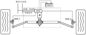
Fig. 1 is a schematic structural diagram of a steer-by-wire system for rear wheels with a center self-locking function according to the present invention.
FIG. 2 is a front cross-sectional view of the rear wheel steer-by-wire with center self-locking feature of the present invention.
FIG. 3 is a longitudinal cross-sectional view of the rear wheel steer-by-wire with center self-locking feature of the present invention.
Fig. 4 is a schematic diagram of a redundant motor scheme of the rear wheel steering gear with a neutral self-locking function according to the invention.
FIG. 5 is a flowchart of a control method of the rear wheel steering system with neutral self-locking function according to the present invention.
In the above fig. 2, 3 and 4, 1 is a hinge head; 2 is a screw shaft; 3 is a supporting sliding bearing; 4 is a left steering gear shell; 5 is a screw nut; 6 is a tooth flank locking nut; 7 is a nut supporting bearing; 8 is a slotted external thread nut; 9 is a worm; 10 is a circulating steel ball; 11 is a worm wheel; 12 is a motor flange; 13 is a worm gear flange; 14 is a controller; 15 is the shell of the electric device; 16 is a motor; 1601 a brushless motor; 1602 is a brush motor with a clutch; 17 is a coupling; 18 is a worm first bearing; 19 is a worm second bearing; and 20 is an oil seal.
Detailed Description
As shown in fig. 1, the electronic control unit executes a steering angle instruction sent by a vehicle Controller Area Network (CAN) bus according to the collected SAS1/SAS2 wheel steering angle signals, vehicle speed, engine and other signals, and the steering controller feeds the wheel state back to the vehicle controller.
As shown in fig. 2, the motor 16 and its controller 14 are integrated together, and the controller 14 is at the tail of the motor 16. The self-locking worm and gear speed reducing mechanism is used as a first-stage speed reducing mechanism of the output torque of the motor to reduce the speed and increase the torque of the motor. The ball screw speed reducing mechanism is used as a second-stage speed reducing mechanism, changes rotation into linear motion of a screw, and generates driving force to drive the left and right pull rods so as to drive the steering knuckle to steer the wheel.
As shown in fig. 2 and 3, one end of the worm 9 of the worm-worm reducer is connected through a coupling 17 to transmit the torque of the motor 16. The other end of the nut extends out of the shell 15 of the electric device and is processed into a hexagonal nut shape for manual homing of system faults, and the working position of the system can be adjusted to the zero position by manually rotating the nut when the system has a fault at the non-zero position. At this moment, utilize the instrument to rotate manual adjusting nut 8, make the wheel be in the zero angle, form traditional system of traveling, because the reverse auto-lock ability of worm gear, make the rear wheel can keep the zero angle state, make the vehicle keep can the normal driving state.
The worm gear is pressed on the worm gear flange 13 in an interference mode, flat key connection can be arranged for further keeping stable power transmission, and the worm gear flange 13 is fixed on the lead screw nut 5 through bolts. The unfolding spiral angle of the worm 9 is less than or equal to 4 degrees and smaller than the contact friction angle of the worm gear and the worm, the material of the worm 9 is 40Cr, and the material of the worm wheel 11 is tin bronze. The reverse self-locking of the worm gear speed reducing mechanism determines the unidirectionality of motion transmission, namely when the motor stops working, the position of the screw shaft is locked, so that the rear wheel steering-by-wire steering gear is in a locking state when the rear wheel steering is not needed.
Among the ball screw reduction gears, worm wheel flange 13 hole department design has the steel pipe to guarantee the circulation flow of circulation steel ball 10 on nut 5, nut 5 keeps away from one side of worm wheel flange 13, be equipped with bearing 7, the bearing 7 inner circle is by tooth abdomen lock nut 6 locking, the design of bearing 7 outer lane has the axle shoulder to lean on fluting external screw thread nut 8 to lock on steering gear left shell 4, thereby make the axial position of nut 5 fixed, can make screw shaft 2 carry out axial linear motion with the rotary motion of guaranteeing nut 5, screw shaft 2 both ends processing has articulated ball head 1, be connected with the steering linkage.
As shown in fig. 4, preferably, one end of the worm 9 is connected to the motor 1601 by a coupling 17, and another set of brush motor with clutch 1602 may be arranged at the other end for redundancy of the system, and when the motor 1601 and its controller fail, the brush motor with clutch 1602 is engaged by the clutch, and its controller controls the brush motor with clutch 1602 to implement a rear wheel steering function.
As shown in fig. 5, the control method can acquire the current rear wheel rotation angle through the angle sensors respectively arranged at the upper ends of the left and right rear wheel kingpins. A central rotating shaft in the angle sensors is rigidly connected with a main pin shaft, and the two angle sensors are redundant mutually and feed back the rotation angle of the wheel to the controller in real time. And under the four-wheel working mode, the upper layer obtains the target turning angle of the rear wheel steering through the table look-up of the turning angle of the front wheel and the vehicle speed signal. The lower layer controls a motor of the steer-by-wire device to servo a target corner obtained by the upper layer, and the target angle is servoed by controlling the motor current, the motor rotating speed and the position of the actuating motor, so that the steering wheel is driven to realize the control of the corner. The controller is in standby in a two-wheel steering mode, only detects whether the angle sensor is in a zero position, and drives the motor to return to the middle position if the deviation between the angle sensor and the zero position is larger; when the rear wheel steering is not needed, the rear wheel steering device is in a locking state and no energy consumption is generated.
In terms of flow, after the vehicle is powered on, firstly, initializing parameters, and judging whether the vehicle is in a four-wheel mode or a two-wheel mode; under the four-wheel working mode, the corners of the front wheel and the rear wheel are collected, and the four-wheel steering is realized by controlling the rear wheel through two layers of control strategies: the upper layer obtains the target turning angle of the rear wheel steering through a front wheel turning angle and vehicle speed signal table look-up (MAP graph obtained by optimizing the whole vehicle dynamics); the lower layer controls a motor of the steer-by-wire device to servo a target corner obtained by the upper layer, and the target angle is servoed by controlling the motor current, the motor rotating speed and the position of the actuating motor, so that the steering wheel is driven to realize the control of the corner. In the two-wheel working mode, whether the position is in a middle position or not is judged firstly, if not, the electric device is enabled to return the position of the rear wheel to zero by controlling the motor, and if the position is in the middle position after power-on, the system is in a standby state and only the angle of the rear wheel is monitored.
Claims (6)
Priority Applications (1)
| Application Number | Priority Date | Filing Date | Title |
|---|---|---|---|
| CN201911288306.0A CN110901753A (en) | 2019-12-16 | 2019-12-16 | A rear wheel steering by wire with neutral position self-locking function and its control method |
Applications Claiming Priority (1)
| Application Number | Priority Date | Filing Date | Title |
|---|---|---|---|
| CN201911288306.0A CN110901753A (en) | 2019-12-16 | 2019-12-16 | A rear wheel steering by wire with neutral position self-locking function and its control method |
Publications (1)
| Publication Number | Publication Date |
|---|---|
| CN110901753A true CN110901753A (en) | 2020-03-24 |
Family
ID=69824393
Family Applications (1)
| Application Number | Title | Priority Date | Filing Date |
|---|---|---|---|
| CN201911288306.0A Pending CN110901753A (en) | 2019-12-16 | 2019-12-16 | A rear wheel steering by wire with neutral position self-locking function and its control method |
Country Status (1)
| Country | Link |
|---|---|
| CN (1) | CN110901753A (en) |
Cited By (3)
| Publication number | Priority date | Publication date | Assignee | Title |
|---|---|---|---|---|
| CN113942567A (en) * | 2021-10-29 | 2022-01-18 | 杭州世宝汽车方向机有限公司 | Double-motor driven steering gear |
| CN114701565A (en) * | 2022-05-27 | 2022-07-05 | 北京理工大学 | Four-wheel steering independent wheel steering driving device and control method thereof |
| CN117104333A (en) * | 2023-09-01 | 2023-11-24 | 湖北汽车工业学院 | A control and control method for returning the rear wheel steering system to the neutral position under fault conditions |
Citations (10)
| Publication number | Priority date | Publication date | Assignee | Title |
|---|---|---|---|---|
| JPH0551507B2 (en) * | 1985-01-24 | 1993-08-02 | Honda Motor Co Ltd | |
| JP2004114941A (en) * | 2002-09-27 | 2004-04-15 | Aisin Seiki Co Ltd | Rear wheel steering device |
| CN1931649A (en) * | 2005-09-14 | 2007-03-21 | 比亚迪股份有限公司 | String driven vehicle steering system and its control method |
| CN205113421U (en) * | 2015-11-09 | 2016-03-30 | 天津职业技术师范大学 | Semi -mounted road train four wheel steering control system |
| US20170341681A1 (en) * | 2014-12-16 | 2017-11-30 | Hitachi Automotive Systems, Ltd. | Water detection system and electric power steering apparatus |
| WO2018068933A1 (en) * | 2016-10-12 | 2018-04-19 | Robert Bosch Gmbh | Steering system |
| CN109249985A (en) * | 2017-07-12 | 2019-01-22 | 株式会社捷太格特 | Transfer |
| CN109591881A (en) * | 2017-09-30 | 2019-04-09 | 比亚迪股份有限公司 | Rear-axle steering device, vehicle and its rear-wheel steering system |
| CN109606465A (en) * | 2019-02-02 | 2019-04-12 | 北京奥特尼克科技有限公司 | An electro-hydraulic steering gear with redundant motors for advanced autonomous driving |
| CN110001765A (en) * | 2019-02-02 | 2019-07-12 | 北京奥特尼克科技有限公司 | A kind of automobile-used steer by wire apparatus and control method with redundant unit |
-
2019
- 2019-12-16 CN CN201911288306.0A patent/CN110901753A/en active Pending
Patent Citations (10)
| Publication number | Priority date | Publication date | Assignee | Title |
|---|---|---|---|---|
| JPH0551507B2 (en) * | 1985-01-24 | 1993-08-02 | Honda Motor Co Ltd | |
| JP2004114941A (en) * | 2002-09-27 | 2004-04-15 | Aisin Seiki Co Ltd | Rear wheel steering device |
| CN1931649A (en) * | 2005-09-14 | 2007-03-21 | 比亚迪股份有限公司 | String driven vehicle steering system and its control method |
| US20170341681A1 (en) * | 2014-12-16 | 2017-11-30 | Hitachi Automotive Systems, Ltd. | Water detection system and electric power steering apparatus |
| CN205113421U (en) * | 2015-11-09 | 2016-03-30 | 天津职业技术师范大学 | Semi -mounted road train four wheel steering control system |
| WO2018068933A1 (en) * | 2016-10-12 | 2018-04-19 | Robert Bosch Gmbh | Steering system |
| CN109249985A (en) * | 2017-07-12 | 2019-01-22 | 株式会社捷太格特 | Transfer |
| CN109591881A (en) * | 2017-09-30 | 2019-04-09 | 比亚迪股份有限公司 | Rear-axle steering device, vehicle and its rear-wheel steering system |
| CN109606465A (en) * | 2019-02-02 | 2019-04-12 | 北京奥特尼克科技有限公司 | An electro-hydraulic steering gear with redundant motors for advanced autonomous driving |
| CN110001765A (en) * | 2019-02-02 | 2019-07-12 | 北京奥特尼克科技有限公司 | A kind of automobile-used steer by wire apparatus and control method with redundant unit |
Non-Patent Citations (2)
| Title |
|---|
| 汪东明等: "电控电动式四轮转向系统的研究与发展" * |
| 汪东明等: "电控电动式四轮转向系统的研究与发展", 《汽车电器》 * |
Cited By (3)
| Publication number | Priority date | Publication date | Assignee | Title |
|---|---|---|---|---|
| CN113942567A (en) * | 2021-10-29 | 2022-01-18 | 杭州世宝汽车方向机有限公司 | Double-motor driven steering gear |
| CN114701565A (en) * | 2022-05-27 | 2022-07-05 | 北京理工大学 | Four-wheel steering independent wheel steering driving device and control method thereof |
| CN117104333A (en) * | 2023-09-01 | 2023-11-24 | 湖北汽车工业学院 | A control and control method for returning the rear wheel steering system to the neutral position under fault conditions |
Similar Documents
| Publication | Publication Date | Title |
|---|---|---|
| US9022167B2 (en) | Hybrid power steering system | |
| CN107826164B (en) | A multi-wheel steering system and control method based on electric power assistance | |
| CN111845931B (en) | A multi-mode composite steering chassis and construction machinery vehicle | |
| US20050178606A1 (en) | Motor vehicle steering system | |
| CN209241163U (en) | Power Steering Systems and Electric Vehicles | |
| CN107600171B (en) | Steering method for wheel rim/hub driven multi-axle vehicle | |
| CN102069843A (en) | Wire controlled wheel independent steering execution mechanism and wheel assembly | |
| JP4485802B2 (en) | Hydraulic servo steering device | |
| US12110067B2 (en) | Electric commercial vehicle power steering system with a globoidal wormgearing | |
| US20070029748A1 (en) | Steering system | |
| US20240157999A1 (en) | Methods and systems for a steer-by-wire system with sensor devices | |
| CN109987135B (en) | Steering system for heavy vehicle | |
| CN108001522A (en) | A kind of heavy goods vehicles R type electric power-assisted steering apparatus | |
| CN110884564B (en) | Electric servo angle steering gear | |
| CN111301515A (en) | Control method of rear wheel linear control electro-hydraulic steering system | |
| JP2019006225A (en) | Hub unit with auxiliary steering function and vehicle | |
| CN116968805B (en) | A steering axle, a steering control system and a crane | |
| CN215205051U (en) | Electric power-assisted steering mechanism | |
| JP5226999B2 (en) | Vehicle steering device | |
| CN213862397U (en) | Electric motor car intelligence driving steer-by-wire system | |
| CN112477979A (en) | Electric power-assisted steering mechanism | |
| CN107458458A (en) | Automobile chassis assembly | |
| CN209382077U (en) | Five semitrailer initiative differential angle a steering system | |
| CN115465357B (en) | Active steering systems and vehicles | |
| CN219524009U (en) | Steering system and crane |
Legal Events
| Date | Code | Title | Description |
|---|---|---|---|
| PB01 | Publication | ||
| PB01 | Publication | ||
| SE01 | Entry into force of request for substantive examination | ||
| SE01 | Entry into force of request for substantive examination | ||
| RJ01 | Rejection of invention patent application after publication |
Application publication date: 20200324 |
|
| RJ01 | Rejection of invention patent application after publication |