CN110901883B - Tethered UAV and UAV Airborne Terminal - Google Patents
Tethered UAV and UAV Airborne Terminal Download PDFInfo
- Publication number
- CN110901883B CN110901883B CN201911216988.4A CN201911216988A CN110901883B CN 110901883 B CN110901883 B CN 110901883B CN 201911216988 A CN201911216988 A CN 201911216988A CN 110901883 B CN110901883 B CN 110901883B
- Authority
- CN
- China
- Prior art keywords
- arm body
- arm
- uav
- airborne
- horn
- Prior art date
- Legal status (The legal status is an assumption and is not a legal conclusion. Google has not performed a legal analysis and makes no representation as to the accuracy of the status listed.)
- Active
Links
Images

Classifications
-
- B—PERFORMING OPERATIONS; TRANSPORTING
- B64—AIRCRAFT; AVIATION; COSMONAUTICS
- B64C—AEROPLANES; HELICOPTERS
- B64C1/00—Fuselages; Constructional features common to fuselages, wings, stabilising surfaces or the like
- B64C1/30—Parts of fuselage relatively movable to reduce overall dimensions of aircraft
-
- B—PERFORMING OPERATIONS; TRANSPORTING
- B64—AIRCRAFT; AVIATION; COSMONAUTICS
- B64C—AEROPLANES; HELICOPTERS
- B64C27/00—Rotorcraft; Rotors peculiar thereto
- B64C27/04—Helicopters
- B64C27/08—Helicopters with two or more rotors
-
- B—PERFORMING OPERATIONS; TRANSPORTING
- B64—AIRCRAFT; AVIATION; COSMONAUTICS
- B64U—UNMANNED AERIAL VEHICLES [UAV]; EQUIPMENT THEREFOR
- B64U10/00—Type of UAV
- B64U10/10—Rotorcrafts
-
- B—PERFORMING OPERATIONS; TRANSPORTING
- B64—AIRCRAFT; AVIATION; COSMONAUTICS
- B64U—UNMANNED AERIAL VEHICLES [UAV]; EQUIPMENT THEREFOR
- B64U50/00—Propulsion; Power supply
- B64U50/10—Propulsion
- B64U50/19—Propulsion using electrically powered motors
Landscapes
- Engineering & Computer Science (AREA)
- Aviation & Aerospace Engineering (AREA)
- Mechanical Engineering (AREA)
- Chemical & Material Sciences (AREA)
- Combustion & Propulsion (AREA)
- Remote Sensing (AREA)
- Toys (AREA)
Abstract
本发明公开了一种系留无人机及无人机机载端。无人机机载端包括机体和连接于机体的多个机臂,机臂连接旋翼,机臂包括沿着设定直线方向依次设置的第一臂体和连接于第一臂体的第二臂体,第一臂体固定于机体,第二臂体连接于长度调节器的输出端,长度调节器输出沿设定直线方向的运动,以带动第二臂相对于第一臂体运动。通过将机臂设置两段式结构,调节臂体之间的相对位置可调节机臂的总长度,实现无人机机载端的变轴距设计,无人机可根据不同风力环境调整所需轴距,增强无人机稳定性。
The invention discloses a tethered unmanned aerial vehicle and an airborne terminal of the unmanned aerial vehicle. The airborne end of the UAV includes a body and a plurality of arms connected to the body. The arms are connected to the rotor. The arms include a first arm body arranged in sequence along a set straight line direction and a second arm body connected to the first arm body. body, the first arm body is fixed on the machine body, the second arm body is connected to the output end of the length adjuster, and the length adjuster outputs a movement along a set linear direction to drive the second arm body to move relative to the first arm body. By setting the arm in a two-stage structure, adjusting the relative position between the arms can adjust the total length of the arm, and realize the variable wheelbase design of the drone's airborne end. The drone can adjust the required axis according to different wind environments. to enhance the stability of the UAV.
Description
技术领域technical field
本发明涉及无人机技术领域,特别涉及一种系留无人机及无人机机载端。The invention relates to the technical field of unmanned aerial vehicles, in particular to a tethered unmanned aerial vehicle and an onboard terminal of the unmanned aerial vehicle.
背景技术Background technique
系留无人机是指通过将多旋翼无人机与系留线缆相结合以便实现无人机长时间滞空的无人机系统。系留无人机主要应用于通信中继、侦察监控等应用领域。Tethered UAVs refer to UAV systems that combine multi-rotor UAVs with tethered cables to achieve long-term airborne UAVs. Tethered UAVs are mainly used in communication relay, reconnaissance and monitoring and other application fields.
其中,系留无人机的机载端通常采用定轴距设计,即相对旋翼之间的距离是一定的。定轴距的设计限定了无人机机载端的抗风能力,使得无人机机载端无法适应较大范围的风力环境。Among them, the airborne end of the tethered UAV is usually designed with a fixed wheelbase, that is, the distance between the relative rotors is constant. The design of the fixed wheelbase limits the wind resistance of the drone's airborne end, making it impossible for the drone's airborne end to adapt to a wide range of wind conditions.
因此,如何提高无人机机载端在不同风力环境下的适应能力,提高无人机平台稳定性,是本领域技术人员目前需要解决的技术问题。Therefore, how to improve the adaptability of the UAV airborne terminal in different wind environments and how to improve the stability of the UAV platform is a technical problem to be solved by those skilled in the art.
发明内容Contents of the invention
有鉴于此,本发明的目的是提供一种无人机机载端,其抗风能力对环境的适应性较好。本发明的另一目的是提供一种包括上述无人机机载端的系留无人机,其中的无人机机载端的抗风能力对环境的适应性较好。In view of this, the object of the present invention is to provide an airborne terminal of a UAV, whose wind resistance ability is better adaptable to the environment. Another object of the present invention is to provide a tethered UAV including the above-mentioned UAV onboard end, wherein the wind resistance of the UAV onboard end is better adaptable to the environment.
为实现上述目的,本发明提供如下技术方案:To achieve the above object, the present invention provides the following technical solutions:
一种无人机机载端,包括机体和连接于所述机体的多个机臂,所述机臂连接旋翼,所述机臂包括沿着设定直线方向依次设置的第一臂体和连接于所述第一臂体的第二臂体,所述第一臂体固定于所述机体,所述第二臂体连接于长度调节器的输出端,所述长度调节器输出沿所述设定直线方向的运动,以带动所述第二臂体相对于所述第一臂体运动。An airborne terminal of an unmanned aerial vehicle, including a body and a plurality of arms connected to the body, the arms are connected to the rotor, and the arms include first arms and connecting arms arranged in sequence along a set straight line direction The second arm body of the first arm body is fixed to the body, the second arm body is connected to the output end of the length adjuster, and the output end of the length adjuster is along the The motion in the linear direction is fixed to drive the second arm body to move relative to the first arm body.
优选地,所述机臂中,所述第一臂体远离所述机体的端部与所述第二臂体靠近所述机体的端部滑动套接,且滑动方向沿所述预设直线方向。Preferably, in the machine arm, the end of the first arm away from the machine body is slidably socketed with the end of the second arm close to the machine body, and the sliding direction is along the preset linear direction .
优选地,所述长度调节器包括设于机体中的旋转电机和连接于所述旋转电机的输出端的丝杠螺母组件,所述第二臂体连接于所述丝杠螺母组件的输出端,所述丝杠螺母组件输出沿着对应的所述预设直线方向的直线运动。Preferably, the length adjuster includes a rotating motor arranged in the machine body and a lead screw nut assembly connected to the output end of the rotating motor, the second arm body is connected to the output end of the lead screw nut assembly, so The screw nut assembly outputs linear motion along the corresponding preset linear direction.
优选地,还包括支撑架,所述支撑架包括两个相铰接的支撑杆,所述支撑架中的两个所述支撑杆的自由端分别铰接于同一所述机臂中的所述第一臂体和所述第二臂体的下方。Preferably, a support frame is also included, the support frame includes two hinged support rods, and the free ends of the two support rods in the support frame are respectively hinged to the first below the arm body and the second arm body.
优选地,各所述机臂下均对应设置一个所述支撑架。Preferably, one support frame is correspondingly arranged under each arm.
一种系留无人机,包括地面端和机载端,所述地面端通过系留线缆电连接所述机载端,所述机载端为如上述任一项所述无人机机载端。A tethered unmanned aerial vehicle, including a ground terminal and an airborne terminal, the ground terminal is electrically connected to the airborne terminal through a tethered cable, and the airborne terminal is an unmanned aerial vehicle as described in any one of the above loading end.
优选地,所述机载端包括连接于所述第二臂体上的高压电调和连接于所述高压电调的输出端的高压电机,所述高压电机的输出端连接所述旋翼。Preferably, the on-board end includes a high-voltage electric regulator connected to the second arm body and a high-voltage motor connected to an output end of the high-voltage electric regulator, and an output end of the high-voltage electric motor is connected to the rotor.
优选地,所述机臂上的所述高压电机、所述高压电调与所述旋翼构成动力模块;所述动力模块通过所述高压电调可拆卸连接于所述机臂。Preferably, the high-voltage motor on the arm, the high-voltage electric regulator and the rotor form a power module; the power module is detachably connected to the arm through the high-voltage electric regulator.
本发明提供的无人机机载端,包括机体和连接于机体的多个机臂,机臂连接旋翼,机臂包括沿着设定直线方向依次设置的第一臂体和连接于第一臂体的第二臂体,第一臂体固定于机体,第二臂体连接于长度调节器的输出端,长度调节器输出沿设定直线方向的运动,以带动第二臂相对于第一臂体运动。The airborne end of the UAV provided by the present invention includes a body and a plurality of arms connected to the body, the arms are connected to the rotor, and the arms include first arms arranged in sequence along the set straight line direction and connected to the first arm The second arm of the body, the first arm is fixed on the body, the second arm is connected to the output end of the length adjuster, and the length adjuster outputs the movement along the set linear direction to drive the second arm relative to the first arm body movement.
通过将机臂设置两段式结构,调节臂体之间的相对位置可调节机臂的总长度,实现无人机机载端的变轴距设计,无人机可根据不同风力环境调整所需轴距,调整抗风能力,使无人机在不同风力环境下具有更好稳定性,具体可以在风力较小的无人机起飞时,处于较小的轴距形式,这种状态下,无人机更灵活,但是抗风能力较低,无人机升空后,由于风力增大,可增大轴距,轴距的增大使得抗风能力增强。By setting the two-stage structure of the arm, adjusting the relative position between the arms can adjust the total length of the arm, and realize the variable wheelbase design of the drone's airborne end, and the drone can adjust the required axis according to different wind environments distance, adjust the wind resistance, so that the UAV has better stability in different wind environments. Specifically, when the UAV with less wind takes off, it can be in the form of a smaller wheelbase. In this state, no one The drone is more flexible, but its wind resistance is low. After the drone is lifted into the air, due to the increase in wind force, the wheelbase can be increased. The increase of the wheelbase increases the wind resistance.
本发明提供的包括上述无人机机载端的系留无人机,其中的无人机机载端的抗风能力对环境的适应性较好。The present invention provides a tethered UAV including the above-mentioned UAV onboard end, wherein the wind resistance of the UAV onboard end has better adaptability to the environment.
一种优选的实施方式中,该系留无人机可以通过选择不同的动力模块从而使得无人机能够在更广的海拔范围内起降。In a preferred embodiment, the tethered drone can take off and land at a wider altitude range by selecting different power modules.
附图说明Description of drawings
为了更清楚地说明本发明实施例或现有技术中的技术方案,下面将对实施例或现有技术描述中所需要使用的附图作简单地介绍,显而易见地,下面描述中的附图仅仅是本发明的实施例,对于本领域普通技术人员来讲,在不付出创造性劳动的前提下,还可以根据提供的附图获得其他的附图。In order to more clearly illustrate the technical solutions in the embodiments of the present invention or the prior art, the following will briefly introduce the drawings that need to be used in the description of the embodiments or the prior art. Obviously, the accompanying drawings in the following description are only It is an embodiment of the present invention, and those skilled in the art can also obtain other drawings according to the provided drawings without creative work.
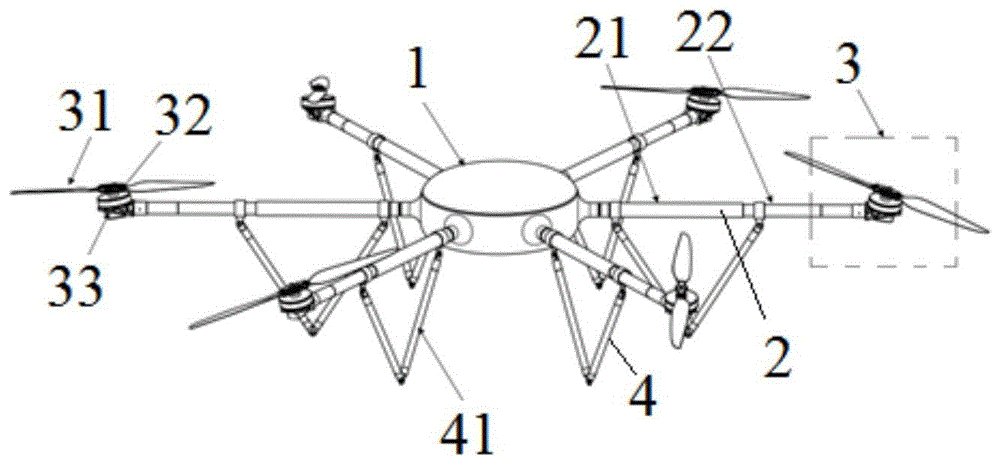
图1为本发明中系留无人机的无人机机载端的结构图。Fig. 1 is the structural diagram of the UAV airborne end of the tethered UAV in the present invention.
附图标记:Reference signs:
机体1,机臂2,第一臂体21,第二臂体22,动力模块3,旋翼31,高压电机32,高压电调33,支撑架4,支撑杆41。
具体实施方式detailed description
下面将结合本发明实施例中的附图,对本发明实施例中的技术方案进行清楚、完整地描述,显然,所描述的实施例仅仅是本发明一部分实施例,而不是全部的实施例。基于本发明中的实施例,本领域普通技术人员在没有做出创造性劳动前提下所获得的所有其他实施例,都属于本发明保护的范围。The following will clearly and completely describe the technical solutions in the embodiments of the present invention with reference to the accompanying drawings in the embodiments of the present invention. Obviously, the described embodiments are only some, not all, embodiments of the present invention. Based on the embodiments of the present invention, all other embodiments obtained by persons of ordinary skill in the art without making creative efforts belong to the protection scope of the present invention.
本发明的核心是提供一种无人机机载端,其抗风能力对环境的适应性较好。本发明的另一核心是提供一种包括上述无人机机载端的系留无人机,其中的无人机机载端的抗风能力对环境的适应性较好。The core of the present invention is to provide an airborne terminal of the UAV, whose wind resistance ability is better adaptable to the environment. Another core of the present invention is to provide a tethered UAV including the above-mentioned UAV onboard end, wherein the wind resistance of the UAV onboard end is better adaptable to the environment.
在本发明的描述中,需要说明的是,当元件被称为“固定于”另一个元件,它可以直接在另一个元件上或者也可以存在居中的元件。当一个元件被认为是“连接”另一个元件,它可以是直接连接到另一个元件或者可能同时存在居中元件。术语“上”、“下”等指示的方位或位置关系为基于附图所示的方位或位置关系,仅是为了便于描述本发明和简化描述,而不是指示或暗示所指的装置或元件必须具有特定的方位、以特定的方位构造和操作,因此不能理解为对本发明的限制。此外,术语“第一”、“第二”仅用于描述目的,而不能理解为指示或暗示相对重要性。此外,在本发明的描述中,除非另有说明,“多个”的含义是两个或两个以上。In the description of the present invention, it should be noted that when an element is referred to as being "fixed" to another element, it can be directly on the other element or there can also be an intervening element. When an element is referred to as being "connected to" another element, it can be directly connected to the other element or intervening elements may also be present. The orientation or positional relationship indicated by the terms "upper", "lower", etc. is based on the orientation or positional relationship shown in the drawings, and is only for the convenience of describing the present invention and simplifying the description, rather than indicating or implying that the referred device or element must Having a particular orientation, being constructed and operating in a particular orientation, and therefore not to be construed as limiting the invention. In addition, the terms "first" and "second" are used for descriptive purposes only, and should not be understood as indicating or implying relative importance. In addition, in the description of the present invention, unless otherwise specified, "plurality" means two or more.
本发明所提供无人机机载端的一种具体实施例中,请参考图1,包括机体1和连接于机体1的多个机臂2,机臂2连接旋翼31。机臂2包括沿着设定直线方向依次设置的第一臂体21和连接于第一臂体21的第二臂体22。其中,各机臂2对应的设定直线方向可以按需设定,不做具体限定,如图1所示实施例,机臂2为6个且两两相对设置,相对设置的两个机臂2对应相同的设定直线方向。In a specific embodiment of the airborne end of the drone provided by the present invention, please refer to FIG. 1 , which includes a
在机臂2中,第一臂体21固定于机体1,可选地,第一臂体21上设置外螺纹,通过该外螺纹拧紧固定在机体1的螺纹孔中,又或者,第一臂体21与机体1焊接连接。第二臂体22连接于长度调节器的输出端,长度调节器输出的运动方向沿设定直线方向,以带动第二臂体22相对于第一臂体21运动,在长度调节器的驱动下,第二臂体22可以沿着对应的设定直线方向相对于第一臂体21直线运动,从而改变机臂2的总长度,调节旋翼31轴距。长度调节器具体连接机体或第一臂体。In the
本实施例中,通过将机臂2设置两段式结构,调节臂体之间的相对位置可调节机臂2的总长度,实现无人机机载端的变轴距设计,无人机可根据不同风力环境调整所需轴距,以调整抗风能力,使无人机机载端能够适应飞行环境中的风力,在不同风力环境下具有更好稳定性,具体可以在风力较小的无人机起飞时,处于较小的轴距形式,这种状态下,无人机更灵活,但是抗风能力较低,无人机升空后,由于风力增大,可增大轴距,轴距的增大使得抗风能力增强,可提高各飞行高度下的飞行平稳性。In this embodiment, by setting the
进一步地,机臂2中,第一臂体21远离机体1的端部与第二臂体22靠近机体1的端部滑动套接,且滑动方向沿预设直线方向,则长度调节器驱动第二臂体22运动时,第一臂体21和第二臂体22相对滑动,第一臂体21和第二臂体22之间相套接的部分长度会改变,从而改变机臂2总长度以及旋翼31轴距。通过臂体之间直接滑动连接,可以充分利用臂体本身的空间作为机臂2长度调节空间,提高机臂2长度的可调范围。Further, in the
进一步地,长度调节器包括设置在机体1中的旋转电机和连接于旋转电机的输出端的丝杠螺母组件,第二臂体22连接于丝杠螺母组件的输出端,丝杠螺母组件输出沿着对应的预设直线方向的直线运动。通过丝杠螺母组件与旋转电机的配合,可以较精确地控制所调节的长度值。Further, the length adjuster includes a rotating motor arranged in the
其中,具体地,旋转电机为步进电机。Wherein, specifically, the rotating motor is a stepping motor.
其中,具体地,丝杠螺母组件包括固定连接在第二臂体22内的滑块和与滑块螺纹配合的丝杠,丝杠经第一臂体21内部伸入机体1中连接旋转电机的输出端。第一臂体21和第二臂体22之间具有限转结构以避免两者相对转动。在旋转电机启动时,丝杠转动并带动滑块直线运动,滑块即为丝杠螺母组件与长度调节器的输出端。Wherein, specifically, the lead screw nut assembly includes a slider fixedly connected in the
进一步地,该无人机机载端还包括设置在机臂2下方的支撑架4,支撑架4包括两个相铰接的支撑杆41,支撑架4中的两个支撑杆41的自由端分别铰接于同一机臂2中的第一臂体21和第二臂体22的下方。其中,优选地,各机臂2下均对应设置一个支撑架4。其中,支撑杆41的长度应结合第二臂体22的运动范围需求进行设置。Further, the UAV airborne end also includes a
如图1所示,在起飞之前,支撑架4的两个支撑杆41之间具有夹角,支撑架4与机臂2形成稳定的三角形支撑结构,各支撑架4配合构成起落架;在起飞之后,随着第二臂体22远离第一臂体21的运动,支撑架4的两个支撑杆41之间形成的角度增大,相当于收起起落架,可以减少甚至避免起落架对挂载在机体1下方的光电吊舱、激光雷达等载荷的遮挡,有利于保证成像效果,减少视场盲点;在降落过程中,支撑架4也可作为起落架。As shown in Figure 1, before take-off, there is an included angle between the two
显然,机臂2中的第一臂体21与第二臂体22不限于上述实施例提供的滑动套接。在另一具体实施例中,长度调节器为直线电机,长度调节器的机壳固定连接在第一臂体21远离机体1的一端上,而长度调节器的输出端固定在第二臂体22靠近机体1的一端上,即,第一臂体21、长度调节器、第二臂体22沿着机臂对应的设定直线方向依次设置,第一臂体21通过长度调节器实现与第二臂体22的连接,长度调节器通过输出轴沿对应的设定直线方向的运动实现机臂2总长度的调节。Apparently, the
除了上述无人机机载端,本发明还提供了一种系留无人机,该系留无人机包括地面端和机载端,该机载端具体可以为以上任一实施例中提供的无人机机载端,有益效果可以相应参考以上各个实施例。地面端通过系留线缆电连接机载端。其中,地面端具体包括地面站、地面电源(AC/DC)、卷轴箱、地面电源系统等部分;机载端具体包括机体1、载荷系统、应急电池、旋翼31、飞控计算机、差分天线、设备电源等部件。In addition to the above-mentioned UAV airborne end, the present invention also provides a tethered UAV, which includes a ground end and an airborne end, and the airborne end can be specifically provided in any of the above embodiments. For the beneficial effect of the airborne terminal of the UAV, reference can be made to the above embodiments. The ground terminal is electrically connected to the airborne terminal through a tethered cable. Among them, the ground terminal specifically includes ground station, ground power supply (AC/DC), reel box, ground power supply system and other parts; the airborne terminal specifically includes
其中,优选地,机载端包括连接于第二臂体22上的高压电调33和连接于高压电调33的输出端的高压电机32,高压电机32的输出端连接旋翼31。Wherein, preferably, the airborne end includes a high-voltage
目前,系留无人机旋翼31的电调大多为低压电调,输入电压为50V,而地面供电需要首先从地面由低压变为系留电缆中的高电压(一般为300-400V),以减小线缆传输的损耗,到机载端后,由于低压电调的应用,机载端必须设置机载高压电源模块,以将系留线缆中的高电压转换为低电压,再给电调电机进行供电。机载高压电源模块会随着功率的增大重量和体积增加,使得机载端有效负载减小。At present, most of the ESCs of the moored
本实施例中,由地面电源系统供电给地面电源(AC/DC)将低压转换为高压(通常情况是将220V转换为400V以上,本发明不约束转换的电压具体数值),电流经过地面电源增压后传递给卷轴箱,通过系留线缆传递给机载端,机载端电流一部分直接传递给高压电调33、高压电机32以为旋翼31提供动力,另一部分通过机载电源模块转换为低压,供给飞控计算机、载荷等。控制信号的传递通过系留线缆完成,系留线缆采用光电复合缆,既能完成电流的传递也能完成控制信号和载荷数据的传递。In this embodiment, the ground power supply (AC/DC) is powered by the ground power supply system to convert low voltage to high voltage (usually 220V is converted to more than 400V, and the present invention does not restrict the specific value of the converted voltage), and the current increases through the ground power supply. After being pressed, it is passed to the reel box, and then to the airborne end through the tethered cable. Part of the airborne end current is directly passed to the high-
高压电调33配合高压电机32能够直接将系留线缆中的高电压不经转换直接使用,去掉了旋翼31处的机载高压电源模块,可以进一步优化整机重量及结构设计,减轻了结构重量,减小整机故障率,优化了机体1结构,能够搭载更多载荷,从而提高可靠性;该种方式不会受到外界电磁环境干扰,抗干扰能力强,适应能力广;在相同功率下,高压电调33及高压电机32可使整机电流明显降低,机载动力线缆线径减小,整机线缆重量明显降低;仅有应急电池,整机动力电压提升后,应急电池电压随即提升,其额定容量对应减小,在相同动力功率下,对应急电池的放电倍率要求降低。The high-voltage
其中,优选地,各机臂2上高压电机32、高压电调33与旋翼31分别构成动力模块3,动力模块3通过高压电调33可拆卸连接于机臂2。即,动力模块3为一个整体结构,其与机臂2的连接是通过高压电调33实现的,将高压电调33与机臂2分离,则动力模块3与机臂2分离,将高压电调33与机臂2连接,则动力模块3与机臂2连接。其中,动力模块3同时具备结构安装接口和电气接口。由于动力模块3的整体式可拆卸设置,从而机臂2上可以更换不同尺寸的动力模块3组合,以适应更广泛的飞行环境,例如,在某一型号旋翼下,最大起飞高度为3000米,可以通过更换整个动力模块3使得最大起飞高度提高到5000米,只用更换动力模块3而不用更换机体1。Wherein, preferably, the high-
另外,动力模块3中还可设置安装座以连接机臂2。具体地,动力模块3通过快拆结构与第二臂体22连接,在第二臂体22碳纤维管内部与动力模块3安装座内部有信号与动力电接口,可以在进行结构拆装时同时完成电气接口连接,该种设计可以直接拆装动力模块3,避免了换桨时导致的旋翼31、电机、电调不匹配问题,使得变轴距无人机换桨应用更为广泛。In addition, the
本说明书中各个实施例采用递进的方式描述,每个实施例重点说明的都是与其他实施例的不同之处,各个实施例之间相同相似部分互相参见即可。Each embodiment in this specification is described in a progressive manner, each embodiment focuses on the difference from other embodiments, and the same and similar parts of each embodiment can be referred to each other.
以上对本发明所提供的系留无人机及无人机机载端进行了详细介绍。本文中应用了具体个例对本发明的原理及实施方式进行了阐述,以上实施例的说明只是用于帮助理解本发明的方法及其核心思想。应当指出,对于本技术领域的普通技术人员来说,在不脱离本发明原理的前提下,还可以对本发明进行若干改进和修饰,这些改进和修饰也落入本发明权利要求的保护范围内。The tethered unmanned aerial vehicle and the onboard terminal of the unmanned aerial vehicle provided by the present invention have been introduced in detail above. In this paper, specific examples are used to illustrate the principle and implementation of the present invention, and the descriptions of the above embodiments are only used to help understand the method and core idea of the present invention. It should be pointed out that for those skilled in the art, without departing from the principles of the present invention, some improvements and modifications can be made to the present invention, and these improvements and modifications also fall within the protection scope of the claims of the present invention.
Claims (6)
Priority Applications (1)
| Application Number | Priority Date | Filing Date | Title |
|---|---|---|---|
| CN201911216988.4A CN110901883B (en) | 2019-12-02 | 2019-12-02 | Tethered UAV and UAV Airborne Terminal |
Applications Claiming Priority (1)
| Application Number | Priority Date | Filing Date | Title |
|---|---|---|---|
| CN201911216988.4A CN110901883B (en) | 2019-12-02 | 2019-12-02 | Tethered UAV and UAV Airborne Terminal |
Publications (2)
| Publication Number | Publication Date |
|---|---|
| CN110901883A CN110901883A (en) | 2020-03-24 |
| CN110901883B true CN110901883B (en) | 2022-12-23 |
Family
ID=69821429
Family Applications (1)
| Application Number | Title | Priority Date | Filing Date |
|---|---|---|---|
| CN201911216988.4A Active CN110901883B (en) | 2019-12-02 | 2019-12-02 | Tethered UAV and UAV Airborne Terminal |
Country Status (1)
| Country | Link |
|---|---|
| CN (1) | CN110901883B (en) |
Citations (6)
| Publication number | Priority date | Publication date | Assignee | Title |
|---|---|---|---|---|
| CN107054623A (en) * | 2017-03-13 | 2017-08-18 | 普宙飞行器科技(深圳)有限公司 | Unmanned plane slidingtype horn device and unmanned plane |
| CN107284653A (en) * | 2017-06-22 | 2017-10-24 | 江苏高精机电装备有限公司 | A kind of multi-rotor aerocraft horizontal take-off regulating system and multi-rotor aerocraft |
| KR101863157B1 (en) * | 2018-02-06 | 2018-06-07 | (주)테크맥스텔레콤 | Folding-type Unmanned Aerial Vehicle able to be carried by the portable Bag |
| CN109204794A (en) * | 2017-07-03 | 2019-01-15 | 宜昌兴邦无人机科技有限公司 | Spray the dropproof blade protection device of unmanned plane |
| EP3436349A1 (en) * | 2016-03-28 | 2019-02-06 | Amazon Technologies Inc. | Selectively thrusting propulsion units for aerial vehicles |
| CN110481767A (en) * | 2019-08-28 | 2019-11-22 | 三峡大学 | A foldable variable-pitch four-rotor aircraft based on oil-electric hybrid power and its application method |
Family Cites Families (13)
| Publication number | Priority date | Publication date | Assignee | Title |
|---|---|---|---|---|
| CN104787327B (en) * | 2015-05-12 | 2016-07-06 | 无锡职业技术学院 | A kind of multi-rotor aerocraft of changeable wheelbase |
| CN105197228B (en) * | 2015-10-30 | 2017-09-29 | 深圳市大疆创新科技有限公司 | Foot stool and unmanned vehicle |
| WO2017128318A1 (en) * | 2016-01-29 | 2017-08-03 | SZ DJI Technology Co., Ltd. | Uav with transformable arms |
| EP3971084B1 (en) * | 2016-02-22 | 2026-04-22 | SZ DJI Technology Co., Ltd. | Aéronef multi-rotor pliable |
| CN205418061U (en) * | 2016-03-29 | 2016-08-03 | 深圳市易飞行科技有限公司 | Collapsible unmanned aerial vehicle |
| CN107444622B (en) * | 2016-05-31 | 2020-01-03 | 比亚迪股份有限公司 | A unmanned aerial vehicle that is used for unmanned aerial vehicle's undercarriage subassembly and has it |
| CN106218859B (en) * | 2016-08-19 | 2018-06-05 | 浙江智天科技有限公司 | A kind of four-axle aircraft of easy assembly |
| US20180281933A1 (en) * | 2017-03-31 | 2018-10-04 | Qualcomm Incorporated | Double Folding Drone Arms with Landing Gear |
| CN207157488U (en) * | 2017-07-11 | 2018-03-30 | 广州市妙伊莲科技有限公司 | A kind of unmanned plane of scalable paddle arm and foot stool |
| CN109915254A (en) * | 2017-12-12 | 2019-06-21 | 中电科特种飞机系统工程有限公司 | an aircraft |
| CN208086003U (en) * | 2018-02-05 | 2018-11-13 | 珠海市双捷科技有限公司 | One kind being tethered at unmanned plane |
| CN208325617U (en) * | 2018-04-28 | 2019-01-04 | 上海飞来信息科技有限公司 | The variable multi-rotor aerocraft of wheelbase |
| CN109896004B (en) * | 2019-03-25 | 2022-11-15 | 上海应用技术大学 | Unmanned aerial vehicle with telescopic arm |
-
2019
- 2019-12-02 CN CN201911216988.4A patent/CN110901883B/en active Active
Patent Citations (6)
| Publication number | Priority date | Publication date | Assignee | Title |
|---|---|---|---|---|
| EP3436349A1 (en) * | 2016-03-28 | 2019-02-06 | Amazon Technologies Inc. | Selectively thrusting propulsion units for aerial vehicles |
| CN107054623A (en) * | 2017-03-13 | 2017-08-18 | 普宙飞行器科技(深圳)有限公司 | Unmanned plane slidingtype horn device and unmanned plane |
| CN107284653A (en) * | 2017-06-22 | 2017-10-24 | 江苏高精机电装备有限公司 | A kind of multi-rotor aerocraft horizontal take-off regulating system and multi-rotor aerocraft |
| CN109204794A (en) * | 2017-07-03 | 2019-01-15 | 宜昌兴邦无人机科技有限公司 | Spray the dropproof blade protection device of unmanned plane |
| KR101863157B1 (en) * | 2018-02-06 | 2018-06-07 | (주)테크맥스텔레콤 | Folding-type Unmanned Aerial Vehicle able to be carried by the portable Bag |
| CN110481767A (en) * | 2019-08-28 | 2019-11-22 | 三峡大学 | A foldable variable-pitch four-rotor aircraft based on oil-electric hybrid power and its application method |
Also Published As
| Publication number | Publication date |
|---|---|
| CN110901883A (en) | 2020-03-24 |
Similar Documents
| Publication | Publication Date | Title |
|---|---|---|
| CN103144779B (en) | Many rotor unmanned aircrafts mooring system | |
| RU2441809C2 (en) | Method of control unmanned aircraft and unmanned aircraft complex | |
| CN204055195U (en) | A kind of six rotor diving aircraft | |
| CN107512391B (en) | Rotor unmanned aerial vehicle based on mooring cable power supply | |
| CN105109675B (en) | A kind of steady deformable undercarriage land sky flying robot of passive increasing | |
| CN210526849U (en) | Fixed wing unmanned aerial vehicle of tilting-rotating force | |
| CN101575004A (en) | Flight-mode-variable unmanned aircraft with multiple sets of coaxial rotors | |
| CN104787327B (en) | A kind of multi-rotor aerocraft of changeable wheelbase | |
| CN203318686U (en) | Aerial photography cloud deck for aeromodelling aircraft | |
| US20200039632A1 (en) | Wind Energy Kite Tail | |
| CN203666995U (en) | Three-shaft aerial shooting holder | |
| CN106081088B (en) | A kind of professional big flood for rescue disaster affected people in flood damage rescues unmanned plane | |
| CN107187587B (en) | An intelligent drone for film and television aerial photography | |
| CN106184706A (en) | A kind of H type structure can double-deformation unmanned plane | |
| CN102991663A (en) | System for mooring stratospheric telecommunication platform with rotor wing | |
| CN105416574A (en) | Unmanned aerial vehicle undercarriages | |
| CN103171763A (en) | Novel unmanned plane | |
| CN105235906A (en) | Unmanned aerial vehicle with stay wire structure and application method thereof | |
| CN107985574A (en) | A kind of auxiliary liter of unmanned plane of buoyancy | |
| CN203268313U (en) | Novel unmanned aerial vehicle | |
| CN202953165U (en) | Mooring rotor lift-off platform system | |
| CN212267843U (en) | Double-layer synchronous variable-pitch coaxial rotor unmanned aerial vehicle | |
| CN105978166A (en) | Modular gravity pressing type power-taking apparatus based on power transmission line induction | |
| CN217170973U (en) | Airborne avionics system of large-scale tilt rotor vertical take-off and landing fixed wing unmanned aerial vehicle | |
| CN110901883A (en) | Mooring unmanned aerial vehicle and airborne end thereof |
Legal Events
| Date | Code | Title | Description |
|---|---|---|---|
| PB01 | Publication | ||
| PB01 | Publication | ||
| SE01 | Entry into force of request for substantive examination | ||
| SE01 | Entry into force of request for substantive examination | ||
| GR01 | Patent grant | ||
| GR01 | Patent grant |